EP0615848A1 - Dispositif de guidage d'encre et réservoir d'encre pour tête d'impression à matrice de points - Google Patents
Dispositif de guidage d'encre et réservoir d'encre pour tête d'impression à matrice de points Download PDFInfo
- Publication number
- EP0615848A1 EP0615848A1 EP94101088A EP94101088A EP0615848A1 EP 0615848 A1 EP0615848 A1 EP 0615848A1 EP 94101088 A EP94101088 A EP 94101088A EP 94101088 A EP94101088 A EP 94101088A EP 0615848 A1 EP0615848 A1 EP 0615848A1
- Authority
- EP
- European Patent Office
- Prior art keywords
- ink
- tank
- supply
- guide assembly
- ink supply
- Prior art date
- Legal status (The legal status is an assumption and is not a legal conclusion. Google has not performed a legal analysis and makes no representation as to the accuracy of the status listed.)
- Granted
Links
- 239000011159 matrix material Substances 0.000 title claims abstract description 20
- 239000011148 porous material Substances 0.000 claims description 15
- 239000003086 colorant Substances 0.000 claims description 9
- 239000000976 ink Substances 0.000 description 341
- 238000010276 construction Methods 0.000 description 16
- 238000000034 method Methods 0.000 description 4
- 238000005192 partition Methods 0.000 description 4
- 230000005499 meniscus Effects 0.000 description 3
- 239000011295 pitch Substances 0.000 description 3
- 230000001419 dependent effect Effects 0.000 description 2
- 239000000428 dust Substances 0.000 description 2
- 230000007613 environmental effect Effects 0.000 description 2
- 239000007788 liquid Substances 0.000 description 2
- 239000000463 material Substances 0.000 description 2
- 239000002245 particle Substances 0.000 description 2
- 230000015572 biosynthetic process Effects 0.000 description 1
- 230000000694 effects Effects 0.000 description 1
- 230000001788 irregular Effects 0.000 description 1
- 238000005461 lubrication Methods 0.000 description 1
- 230000007257 malfunction Effects 0.000 description 1
- 239000000203 mixture Substances 0.000 description 1
- 238000000465 moulding Methods 0.000 description 1
- 230000002093 peripheral effect Effects 0.000 description 1
- 230000000717 retained effect Effects 0.000 description 1
- 238000007711 solidification Methods 0.000 description 1
- 230000008023 solidification Effects 0.000 description 1
Images


Classifications
-
- B—PERFORMING OPERATIONS; TRANSPORTING
- B41—PRINTING; LINING MACHINES; TYPEWRITERS; STAMPS
- B41J—TYPEWRITERS; SELECTIVE PRINTING MECHANISMS, i.e. MECHANISMS PRINTING OTHERWISE THAN FROM A FORME; CORRECTION OF TYPOGRAPHICAL ERRORS
- B41J2/00—Typewriters or selective printing mechanisms characterised by the printing or marking process for which they are designed
- B41J2/005—Typewriters or selective printing mechanisms characterised by the printing or marking process for which they are designed characterised by bringing liquid or particles selectively into contact with a printing material
- B41J2/01—Ink jet
- B41J2/17—Ink jet characterised by ink handling
- B41J2/175—Ink supply systems ; Circuit parts therefor
- B41J2/17503—Ink cartridges
- B41J2/17513—Inner structure
-
- B—PERFORMING OPERATIONS; TRANSPORTING
- B41—PRINTING; LINING MACHINES; TYPEWRITERS; STAMPS
- B41J—TYPEWRITERS; SELECTIVE PRINTING MECHANISMS, i.e. MECHANISMS PRINTING OTHERWISE THAN FROM A FORME; CORRECTION OF TYPOGRAPHICAL ERRORS
- B41J2/00—Typewriters or selective printing mechanisms characterised by the printing or marking process for which they are designed
- B41J2/22—Typewriters or selective printing mechanisms characterised by the printing or marking process for which they are designed characterised by selective application of impact or pressure on a printing material or impression-transfer material
- B41J2/23—Typewriters or selective printing mechanisms characterised by the printing or marking process for which they are designed characterised by selective application of impact or pressure on a printing material or impression-transfer material using print wires
- B41J2/235—Print head assemblies
- B41J2/25—Print wires
- B41J2/255—Arrangement of the print ends of the wires
-
- B—PERFORMING OPERATIONS; TRANSPORTING
- B41—PRINTING; LINING MACHINES; TYPEWRITERS; STAMPS
- B41J—TYPEWRITERS; SELECTIVE PRINTING MECHANISMS, i.e. MECHANISMS PRINTING OTHERWISE THAN FROM A FORME; CORRECTION OF TYPOGRAPHICAL ERRORS
- B41J2/00—Typewriters or selective printing mechanisms characterised by the printing or marking process for which they are designed
- B41J2/22—Typewriters or selective printing mechanisms characterised by the printing or marking process for which they are designed characterised by selective application of impact or pressure on a printing material or impression-transfer material
- B41J2/23—Typewriters or selective printing mechanisms characterised by the printing or marking process for which they are designed characterised by selective application of impact or pressure on a printing material or impression-transfer material using print wires
- B41J2/305—Ink supply apparatus
Definitions
- the present invention relates to an ink guide assembly and ink tank for a dot matrix printer head and especially for a wire dot matrix printer head.
- a wire dot matrix printer head has wires supplied with ink at distal end faces
- the present invention relates to a dot matrix printer head and although it is not so restricted, it relates more particularly to a wire dot matrix printer head having wires supplied with ink at distal end faces and movable against a sheet of print paper for transferring ink to the sheet in the form of dots to record a character, a figure, a graphic image or the like on the sheet.
- An ink supply system for a wire dot matrix printer is known in which an ink ribbon is not used, but ink is supplied from an ink tank to the distal ends of the wire and transferred from the wires directly to a sheet of print paper.
- One known ink guide mechanism for such an ink supply system is disclosed in US-A-4,194,846 and comprises a porous member capable of absorbing ink from an ink tank, the ink guide mechanism having wires contacting the porous member.
- the porous member contains fine holes whose sizes or diameters vary in a certain range, with the result that the ink absorbing capability varies from porous member to porous member, and both excessive and insufficient quantities of ink are liable to be supplied to the distal ends of the wires.
- EP-A-97,009 discloses another ink supply mechanism in which ink is supplied from an ink tank to the distal ends of wires by means of a pump.
- the ink supply mechanism of EP-A-97,009 has, however, the disadvantage that the construction of the connection between the pump and a printer head is complex and results in increased cost. It is necessary to provide a good seal so as to obtain good pump performance, and a large-torque drive source is required for driving the pump.
- the ink supply mechanism is particularly complex in the case of a multi-colour printer head, and such an ink supply mechanism is not suitable for use with a small printer head.
- a wire dot matrix printer head comprising an ink tank; a wire guide means having a portion which is arranged to receive ink from the ink tank; and a printing wire a distal end portion of which is mounted in a hole in the wire guide means, the wire guide means having a capillary ink path which communicates both with the said portion of the wire guide means and with a distal end portion of the printing wire so as to supply ink to the latter.
- the ink tank contains liquid ink which enters one end of the capillary ink path, with the result that ink flow is liable to vary or to be interrupted if the liquid ink contains particles of dust etc. which clog the capillary ink path.
- the wire guide means is so constructed that any air which has been drawn into the ink by capillary force cannot escape therefrom prior to reaching the distal end surface of the wire guide means, with the result that the air can expand under the low pressure which is present and cause flow problems. Additionally, no means are provided for preventing excessive ink accumulating on the distal end surface of the wire guide means.
- a wire dot matrix printer head comprising an ink supply means; a wire guide means having a portion which is arranged to receive ink from the ink supply means and which has a distal end surface; and a printing wire a distal end portion of which is mounted in a hole in the wire guide means with a gap therebetween, the wire guide means having a capillary ink path which communicates both with the said portion and the distal end surface of the wire guide means and with the distal end portion of the printing wire so as to supply ink to the latter, the said hole communicating with at least one ink collection groove situated in the distal end surface of the wire guide means into which ink collection groove any excessive ink on the distal end surface of the wire guide means is drawn under capillary attraction, the or each ink collection groove being open to the atmosphere.
- the invention provides a dot matrix printer head comprising an ink supply tank containing ink absorbing means, the ink supply tank having an ink supply port which is arranged to receive ink from the ink absorbing means, characterised in that the ink absorbing means is compressed in the vicinity of the ink supply port.
- the ink absorbing means is preferably compressed by wall means of the ink supply tank.
- the ink absorbing means may have a tapered portion.
- the ink absorbing means may have a thicker portion in the vicinity of the ink supply port.
- the said wall means of the ink supply tank preferably comprises a lid thereof.
- the ink absorbing means preferably has pores therein which increase in size with distance from the ink supply port.
- the head may comprise a wire guide means having a portion which is arranged to receive ink from the ink absorbing means, there being a capillary ink path through the ink absorbing means, the force of capillary attraction in which increases in the direction of the wire guide means, the said portion of the wire guide means extending into the ink tank so as to receive ink directly from a part of the ink absorbing means in which the average diameter of the pores is smallest.
- the said ink absorbing means reduces the chance of particles of dust being carried into the capillary ink path. Moreover, air which has been drawn into the ink by capillary force can escape therefrom through ink collection groove or grooves, while the latter may serve to prevent excessive ink building up on the distal end surface of the wire guide means.
- the said portion of the wire guide means has an ink guide groove therein whose width is less than the average diameter of the smallest pores.
- the width of the gap between a wire guide hole in the wire guide means and a wire therein is substantially less than the width of the ink guide groove.
- the ink supply tank may have an air hole therein which communicates with air in at least one space between the ink absorbing means and an inner wall of the ink supply tank.
- the ink absorbing means is preferably impregnated with ink at a pressure lower than atmospheric pressure, e.g. in the range 5-10 mm Hg.
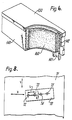
- Figures 6 and 7 of the accompanying drawings illustrate an ink tank construction previously known to the applicants comprising an ink-impregnated member 160, e.g. of a porous material, which fills a tank 140.
- the ink tank construction of Figures 6 and 7 is of a simple shape and can supply a suitable amount of ink to a printer head body under appropriate capillary attraction by the ink-impregnated member 160.
- the member 160 can be impregnated with a large quantity of ink while preventing unwanted ink outflow from an air hole 142 in the tank 140 and from an ink supply port 141.
- the air hole 142 communicates with air in spaces between the ink-impregnated member 160 and the respective inner walls of the tank 140.
- the ink in the ink tank 140 which is remote from the ink supply port is moved toward the ink supply port 141 under a pressure difference which is developed between the ink close to the ink supply port 141 and the ink remote therefrom as capillary attraction of the ink-impregnated member 160 in the vicinity of the ink supply port 141 is increased due to ink consumption.
- ink-impregnated members are generally subjected to an increased resistance to ink flow and to the fact that interrupted ink paths prevent smooth ink flow. If the ink flow is prevented before a pressure difference is produced high enough to move the ink in the ink tank 140, then the ink remote from the ink supply port 141 remains in position and unused, resulting in a short ink supply duration.
- the ink tank 140 frequently has pockets or layers of air trapped therein.
- an air layer 143 communicating directly with the air hole 142 is expanded and is discharged out of the air hole 142 as indicated by arrows A without applying any pressure to the impregnated ink, whereas a pocket 144 of completely trapped air is expanded as indicated by the arrows B and thus moves the surrounding ink.
- the resulting undesired ink outflow can cause a sheet of print paper to be smeared by an ink spot or can allow ink to find its way into the printer head mechanism, with a resulting malfunction of the latter.
- the object of the present invention is thus to provide a construction in which the ink supply is less subjected to temperature and other environmental variations.
- a printer head is adapted for use in a multi-colour printer. Movement is effected of the head of such a printer or of a sheet of print paper or both, a wire corresponding to a desired one of the colours being directed against the print paper at a prescribed position thereon to form an ink dot. Desired characters and figures can thus be produced by repeating the above cycle.
- a sheet of print paper (or other material) may be scanned by a printer head in a direction normal to the direction of feed of the print paper to form a one-dot line in one scanning stroke, and the print paper may be fed along by line pitches to record images.
- a printer head 70 is movable back and forth in the directions of an arrow X, and a sheet of print paper (or other material) 71 is fed along successively at a one line pitch in the direction of an arrow Y.
- An array of wire positions 72, 73, 74, 75 on the printer head 70 extends along a straight line inclined at an angle ⁇ with respect to the scanning directions X, the wire positions being spaced in the direction Y at a pitch of L sin ⁇ .
- Yellow-ink, magenta-ink, cyan-ink, and black-ink wires are located at the positions 72, 73, 74 and 75, respectively, to effect colour-image printing free from undesired colour mixing.
- the present invention is concerned primarily with a printer head, and no further detailed description of the overall printer construction will therefore be given.
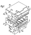
- Figure 1 is an exploded perspective view of a printer head according to the present invention.
- An ink tank 2 is detachably mounted by a holder on top of a printer head body 1.
- the ink tank 2 is of a double construction composed of an ink tank 2b for containing a black ink and an ink tank 2a which is divided into three sections for coloured inks.
- the inks are impregnated in ink-impregnated members 60'' ( Figure 5) of a porous material which are contained in the ink tank 2.
- the printer head body 1 has in its front portion an ink supply guide 12'' ( Figure 4) having ink guide groove means 12''b with an end leading to the respective ink-impregnated member 60'' and a wire guide 13 having a wire guide hole 13a for guiding the tip or distal end portion of a respective printing wire (not shown) therein.
- the ink supply guide 12'' and the wire guide 13 jointly form an ink path from the ink tank 2 to the distal end portion of the wire.
- the printer head shown in Figure 1 is adapted for use in a four-colour printer plotter or in a four-colour image printer, and four wires are employed respectively corresponding to the four colours.
- the distal end portion of the wire is located rearwardly of a distal end surface 13c of the wire guide 13, and the length of the wire is selected such that an ink meniscus formed in a front portion of the wire guide hole 13a covers the distal end of the wire.
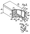
- An ink guide assembly which comprises the ink supply guide 12'' and the wire guide 13, will be described in greater detail with reference to Figure 4.
- the ink supply guide 12'' has a central hole 12''f for guiding the distal end portion of the wire.
- the ink supply guide 12'' also has an axial ink guide groove 12''b leading to the ink-impregnated member 60''.
- the ink guide groove 12''b has a width and a depth selected such that ink will be stably supplied from the ink tank 2 as described later on.
- the ink supply guide 12'' has on a front surface 12''e thereof a circular groove 12''a which communicates with the ink guide grooves 12''b through an inner portion (not shown).
- the wire guide 13 has a proximal end 13d thereof placed in the circular groove 12''a.
- the ink tank 2 or each ink tank 2a, 2b, comprises an ink tank body 40, two stacked ink-impregnated members 61, 62 of a porous material which are disposed in the space in the ink tank body 40 so as to fill the latter, and a lid 50.
- the ink-impregnated members 61, 62 are impregnated with ink at a pressure lower than atmospheric ranging from 5 to 10 mmHg, so that air remaining in the porous ink-impregnated members will be reduced as much as possible to increase the amount of impregnated ink.
- the ink tank body 40 has a bottom 40a provided with a front ink supply port 41 and a front wall 40b having an air hole 42 defined in a stepped portion thereof.
- the ink supply guide 12 has an arm 12d which is inserted in the ink supply port 41 and which projects from the printer head body 1.
- the bottom 40a of the ink tank body 40 has a raised surface 44 in which there are a plurality of slots 45a, 45b, 45c which communicate with the ink supply port 41.
- the slots 45a, 45b, 45c are disposed opposite to and communicate with the ink supply grooves 12b provided in the arm 12d of the ink supply guide 12. Although not shown, the slots 45a, 45b are joined together to form a single slot which together with the slot 45c guides the ink into the ink supply grooves 12b.
- the ink tank body 40 also has a side wall 40c having on its inner wall a plurality of vertical ridges 47 having lower ends held against the bottom 40a and upper ends kept out of contact with the tank lid 50.
- the ink tank body 40 further has a front partition 48 which is disposed behind the air hole 42 and in front of the ink supply port 41, the front partition 48 having one end joined to the side wall 40c.
- the tank lid 50 has on a lower surface thereof a plurality of longitudinal ridges 51.
- the space or hollow interior defined by the bottom 40a, the side wall 40c, the partition 48, and the lid 50 of the tank body 50 accommodates therein the two porous members 61, 62 as double layers which are held in contact with only the raised surface 44 of the bottom 40a, the vertical ridges 47 of the side wall 40c, the partition 48, and the ridges 51 of the lid 50.
- the porous members 61, 62 have different average hole sizes or diameters.
- the porous member 61, which has a larger average hole diameter, is placed on top of the other porous member 62.
- porous member 62 which is closer to the ink supply port 41, is made of a porous material having a smaller average hole diameter than that of the porous member 61, while the porous member 61, which is further from the ink supply port 41 has a greater average hole diameter than that of the porous member 62,
- the capillary attraction is successively greater along the ink path, that is, successively from the porous member 61 having the larger average hole diameter to the porous member 62 having the smaller average hole diameter and thence to the ink guide slots 45a, 45b, 45c provided in the raised surface 44 of the bottom 40a of the ink tank body 40 and so to the ink guide grooves 12b provided in the ink supply guide arm 12d and hence to the gaps between the ink supply guide 12 and the wire guide 13, and finally to the gap between the ink supply guide 12 and the wire 11 and the gap between the wire guide 12 and the wire 11.
- the above capillary attraction setting can be achieved by providing the following dimensions:
- the printer head body 1 has a head frame 30 including side walls extending from upper and back portions of the printer head body 1 and serving as a holder support 31.
- Each of the side walls of the holder support 31 has a holder support hole 32, a leaf spring 36 which is defined by two vertical recesses 33a, 33b in the holder support 31 and which has a holder attachment hole 34, and a guide slot 35.
- a holder 70a has on each of its opposite sides a cylindrical projection 71a, which is rotatably mounted in a holder support hole 32 in the head frame 30, and a semispherical projection 72a, which is engageable in a holder attachment hole 34.
- Each of the ink tanks 2a, 2b has a side disposed closer to the respective holder support 31 and having a cylindrical projection 49 engageable with a lower edge of the respective guide slot 35.
- the ink tank 2 can be attached to the holder 70a and detached therefrom in the following manner.
- the holder 70a is supported in the position shown in Figure 3, and the ink tank 2 is inserted into the holder 70a in the direction of the arrow C. At this time, the ink tank 2 is not required to be accurately positioned in the holder 70a and hence can easily be inserted into the holder 70a. Then, the holder 70a is turned in the direction of the arrow D to bring the projection 49 on each of the sides of the ink tank 2 into contact with an edge of the respective guide slot 35 in the head frame 30, whereupon the ink tank 2 is positioned with respect to the head frame 30.
- the ink supply port 41 is now positioned correctly above the arm 12''d of the ink supply guide 12'' which projects upwardly from the printer head body 1.
- the semispherical projection 72a on each side of the tank holder 70a engages and spreads the leaf springs 36 apart from each other.
- the semispherical projections 72a finally engage in the attachment holes 34 in the leaf springs 36, whereupon the leaf springs 36 return to the vertical positions to retain the holder 70a securely in position.
- the ink tank 2 can be removed in a procedure which is the reverse of the attachment process described above.
- the distal end of the wire projects through the ink meniscus, carries ink thereon, and hits a sheet of print paper (not shown) to transfer the ink to the print paper.
- a sheet of print paper (not shown) to transfer the ink to the print paper.
- the distal end thereof is located inwardly of the distal end surface 13c of the wire guide 13 so that an ink meniscus is formed in front of the distal end of the wire. Accordingly, ink is attached successively to the distal end of the wire as the latter is projected and retracted.
- the transfer of ink to the distal end of the wire, and other details of an inked-wire dot matrix printing process, are described in the above-mentioned EP-A-97009 and will therefore not be described here in greater detail.
- any excessive ink on the distal end surface 13c of the wire guide 13 is drawn under capillary attraction into cross-sectionally V-shaped collection grooves 13b ( Figure 4) provided in the front and side surfaces of the wire guide 13 and is returned to the ink supply guide 12 without smearing the print paper.
- the grooves 13b are thus provided in the distal end surface of the wire guide 13 and communicate with the wire guide hole 13a. As shown in Figure 4, the grooves 13b extend to the outer periphery of the wire guide 13 so as to be open to the atmosphere.
- the wire guide hole 13a should have a proper dimension in the vicinity of the distal end of the wire and a proper amount of ink, without either an excess or a shortage of ink, should be supplied from the ink tank 2.
- the ink guide path from the ink tank 2 to a position in the vicinity of the distal end of the wire is composed of slots, grooves, and gaps.
- An appropriate quantity of ink can be supplied even when the ink supply from the ink supply groove 12''b is reduced due to increased use of ink.
- the dimensions of the ink supply groove and gaps, the hole diameters of the porous member 60'' and the widths of the said slots are selected so that the capillary attraction is progressively greater along the ink path. Therefore, ink will not be interrupted in the ink path as described below.
- the ink tank 2 and the ink guide path for supplying ink to the wire have dimensions dependent on the accuracy of the shapes of the components. Since the components can be easily formed with high dimensional accuracy, as by moulding, the ink tank 2 and the ink guide path can be highly dimensionally accurate and have a stable ink supply capability.
- the ink tank 2 and the ink guide path can easily be assembled as they are composed of a small number of parts. They may be maintained free from wear and deformation for a long period of use and can keep their initial performance partly because of the lubrication effected by the ink.
- the ink guide groove 12''b has mounted therein an ink guide porous member 12''e which serves as an extension of the ink-impregnated member in the ink tank.
- FIG. 5 is an exploded perspective view of an ink tank 2'' which may be used in the present invention.
- the porous member 60'' has different front and rear thicknesses and a tapered portion 60''' therebetween so that the thicker front portion, which is disposed adjacent to the ink supply port 41, is compressed by the tank lid 50 when the porous member 60''' is introduced into the tank body 40. Therefore, even if the porous member 60'' has uniform hole diameters, the front portion thereof, which is adjacent to the ink supply port 41, has a smaller average hole diameter, with the hole diameter becoming progressively greater toward the rear portion, which is remote from the ink supply port 41, at the time when the porous member 60'' is placed in the ink tank body 40.
- the porous member 60'' is structurally equivalent to a plurality of porous sheet layers of different average hole diameters which are placed in the ink tank body 40'' with the average hole diameters becoming progressively greater from the front to rear portion of the member 60.
- the ink tank 2 is placed above the printer head 1, the ink tank 2 may be located below the wires to achieve a stable printing density through the ink guiding process described above.
- ink can be stably supplied through a simple construction from an ink tank to the distal end of a wire, and ink is stably attached to the distal end of the wire for producing a stable and proper ink dot density.
- the ink will not be interrupted in the ink guide path and the risk of a supply failure will be reduced.
- the quantity of ink absorbed in the ink guide path is smaller than would be the case with a known arrangement in which a porous member is used to apply ink to the distal end of the wire. Therefore, any wasted ink which is not used for printing is of a small quantity, and hence substantially all the ink in the ink tank can effectively be used for printing.
- a fresh cartridge ink tank can be mounted in place so that fresh ink can immediately be supplied to the distal end of the wire for resuming the desired printing operation.
- the ink supply system of the invention is simple in construction, it takes up only a small space.
- the ink supply systems for different ink colours can be spaced widely so that any unwanted colour mixing can be avoided.
- a dot matrix printer head which comprises an ink supply tank containing ink absorbing means, the ink supply tank having an ink supply port which is arranged to receive ink from the ink absorbing means, wherein the ink absorbing means is compressed in the vicinity of the ink supply port.
- the ink absorbing means may be compressed by wall means of the ink supply tank. Further, the ink absorbing means may have a tapered portion. The ink absorbing means also may have a thicker portion in the vicinity of the ink supply port.
- the said wall means of the ink supply tank may comprise a lid thereof.
- the ink supply tank may have an air hole therein which communicates with air in at least one space between the ink absorbing means and an inner wall of the ink supply tank.
- the ink absorbing means may have been impregnated with ink at a pressure lower than atmospheric pressure, preferably in the range 5-10 mm Hg.
- the ink absorbing means further may have pores therein which increase in size with distance from the ink supply port.
- the head may comprise an ink guide means having a portion which is arranged to receive ink from the ink absorbing means, there being a capillary ink path through the ink absorbing means the force of capillary attraction in which increases in the direction of the guide means, the said portion of the guide means extending into the ink tank so as to receive ink directly from a part of the ink absorbing means in which the average diameter of the pores is smallest.
- said portion of the wire guide means may have an ink guide groove therein whose width is less than the average diameter of the smallest pores. Also the width of the gap between a wire guide hole in the guide means and a wire therein may be substantially less than the width of the ink guide groove.
- Said portion of the wire guide means further may comprise a porous member.
Landscapes
- Ink Jet (AREA)
- Impact Printers (AREA)
- Impression-Transfer Materials And Handling Thereof (AREA)
Applications Claiming Priority (8)
| Application Number | Priority Date | Filing Date | Title |
|---|---|---|---|
| JP10284384 | 1984-05-22 | ||
| JP10284184 | 1984-05-22 | ||
| JP102843/84 | 1984-05-22 | ||
| JP59102843A JP2563769B2 (ja) | 1984-05-22 | 1984-05-22 | プリンタのインクタンク |
| JP102841/84 | 1984-05-22 | ||
| JP10284184A JPS60245560A (ja) | 1984-05-22 | 1984-05-22 | プリンタのインクタンク |
| EP90201876A EP0398453B1 (fr) | 1984-05-22 | 1984-10-09 | Réservoir d'encre pour une tête d'impression matricielle par points à aguilles |
| EP84306887A EP0139508B1 (fr) | 1983-10-13 | 1984-10-09 | Tête d'impression par points à matrice de fils |
Related Parent Applications (2)
| Application Number | Title | Priority Date | Filing Date |
|---|---|---|---|
| EP90201876A Division EP0398453B1 (fr) | 1984-05-22 | 1984-10-09 | Réservoir d'encre pour une tête d'impression matricielle par points à aguilles |
| EP90201876.1 Division | 1990-07-10 |
Publications (2)
| Publication Number | Publication Date |
|---|---|
| EP0615848A1 true EP0615848A1 (fr) | 1994-09-21 |
| EP0615848B1 EP0615848B1 (fr) | 2001-03-14 |
Family
ID=26443529
Family Applications (10)
| Application Number | Title | Priority Date | Filing Date |
|---|---|---|---|
| EP90201876A Expired - Lifetime EP0398453B1 (fr) | 1984-05-22 | 1984-10-09 | Réservoir d'encre pour une tête d'impression matricielle par points à aguilles |
| EP90201874A Expired - Lifetime EP0406983B1 (fr) | 1984-05-22 | 1984-10-09 | Réservoir d'encre pour une tête d'impression matricielle par points à aguilles |
| EP94101081A Expired - Lifetime EP0605386B1 (fr) | 1984-05-22 | 1984-10-09 | Réservoir d'encre |
| EP94101074A Revoked EP0614761B1 (fr) | 1984-05-22 | 1984-10-09 | Réservoir d'encre |
| EP94101089A Expired - Lifetime EP0605389B1 (fr) | 1984-05-22 | 1984-10-09 | Réservoir d'encre |
| EP94101088A Expired - Lifetime EP0615848B1 (fr) | 1984-05-22 | 1984-10-09 | Réservoir d'encre |
| EP90201873A Expired - Lifetime EP0406982B1 (fr) | 1984-05-22 | 1984-10-09 | Procédé d'imprégnation d'absorbeurs d'encre |
| EP96115079A Withdrawn EP0749839A3 (fr) | 1984-05-22 | 1984-10-09 | Réservoir d'encre |
| EP94101083A Expired - Lifetime EP0605388B1 (fr) | 1984-05-22 | 1984-10-09 | Réservoir d'encre |
| EP94101082A Revoked EP0605387B1 (fr) | 1984-05-22 | 1984-10-09 | Procédé d'imprégnation d'absorbeurs d'encre dans un réservoir d'encre |
Family Applications Before (5)
| Application Number | Title | Priority Date | Filing Date |
|---|---|---|---|
| EP90201876A Expired - Lifetime EP0398453B1 (fr) | 1984-05-22 | 1984-10-09 | Réservoir d'encre pour une tête d'impression matricielle par points à aguilles |
| EP90201874A Expired - Lifetime EP0406983B1 (fr) | 1984-05-22 | 1984-10-09 | Réservoir d'encre pour une tête d'impression matricielle par points à aguilles |
| EP94101081A Expired - Lifetime EP0605386B1 (fr) | 1984-05-22 | 1984-10-09 | Réservoir d'encre |
| EP94101074A Revoked EP0614761B1 (fr) | 1984-05-22 | 1984-10-09 | Réservoir d'encre |
| EP94101089A Expired - Lifetime EP0605389B1 (fr) | 1984-05-22 | 1984-10-09 | Réservoir d'encre |
Family Applications After (4)
| Application Number | Title | Priority Date | Filing Date |
|---|---|---|---|
| EP90201873A Expired - Lifetime EP0406982B1 (fr) | 1984-05-22 | 1984-10-09 | Procédé d'imprégnation d'absorbeurs d'encre |
| EP96115079A Withdrawn EP0749839A3 (fr) | 1984-05-22 | 1984-10-09 | Réservoir d'encre |
| EP94101083A Expired - Lifetime EP0605388B1 (fr) | 1984-05-22 | 1984-10-09 | Réservoir d'encre |
| EP94101082A Revoked EP0605387B1 (fr) | 1984-05-22 | 1984-10-09 | Procédé d'imprégnation d'absorbeurs d'encre dans un réservoir d'encre |
Country Status (4)
| Country | Link |
|---|---|
| EP (10) | EP0398453B1 (fr) |
| DE (9) | DE3486337T2 (fr) |
| HK (3) | HK73495A (fr) |
| SG (7) | SG26403G (fr) |
Families Citing this family (5)
| Publication number | Priority date | Publication date | Assignee | Title |
|---|---|---|---|---|
| JP3582592B2 (ja) | 2001-04-03 | 2004-10-27 | セイコーエプソン株式会社 | インクカートリッジ、及びインクジェット記録装置 |
| CN1081545C (zh) * | 1992-07-24 | 2002-03-27 | 佳能株式会社 | 用于喷墨记录头的墨盒 |
| CA2290698C (fr) * | 1992-07-24 | 2003-12-23 | Canon Kabushiki Kaisha | Reservoir a encre, encre et appareil d'enregistrement a jet d'encre utilisant ce reservoir |
| US6332675B1 (en) | 1992-07-24 | 2001-12-25 | Canon Kabushiki Kaisha | Ink container, ink and ink jet recording apparatus using ink container |
| ES2298890T5 (es) † | 2002-11-26 | 2013-11-29 | Seiko Epson Corporation | Cartucho de tinta |
Citations (6)
| Publication number | Priority date | Publication date | Assignee | Title |
|---|---|---|---|---|
| DE2546835A1 (de) * | 1975-10-18 | 1977-04-28 | Philips Patentverwaltung | Druckeinrichtung mit in laengsrichtung verschiebbaren drucknadeln |
| US4279519A (en) * | 1979-06-01 | 1981-07-21 | Centronics Data Computer Corp. | Dot matrix printing device employing novel image transfer technique for printing on single ply or multiple ply print receiving media |
| EP0042293A2 (fr) * | 1980-06-17 | 1981-12-23 | Seiko Epson Corporation | Imprimante par points avec un fil |
| US4400102A (en) * | 1973-01-05 | 1983-08-23 | Centronics Data Computer Corp. | Multi-color print head |
| EP0139508A2 (fr) * | 1983-10-13 | 1985-05-02 | Seiko Epson Corporation | Tête d'impression par points à matrice de fils |
| JPS60192672A (ja) * | 1984-03-14 | 1985-10-01 | Janome Sewing Mach Co Ltd | プリンタのインク含浸プラテン |
Family Cites Families (14)
| Publication number | Priority date | Publication date | Assignee | Title |
|---|---|---|---|---|
| US3491685A (en) * | 1967-05-24 | 1970-01-27 | Pitney Bowes Inc | Rotatable ink storage and metering cartridge |
| US3863686A (en) * | 1972-10-16 | 1975-02-04 | V Mark Automation Ltd | Apparatus and process for article filling under reduced pressure |
| FR2229320A5 (en) * | 1973-05-09 | 1974-12-06 | Meci Materiel Elect Contr | Continuous inking device for pen recorders - has reservoir containing cellular material to contain ink |
| US4095237A (en) * | 1974-12-26 | 1978-06-13 | Aktiebolaget Electrolux | Ink jet printing head |
| DE2704735C2 (de) * | 1977-02-04 | 1982-08-05 | Siemens AG, 1000 Berlin und 8000 München | Auslaufsicherer Tintenvorratsbehälter |
| JPS55150372A (en) * | 1979-05-11 | 1980-11-22 | Seiko Epson Corp | Printer |
| GB2063175B (en) * | 1979-11-06 | 1984-02-15 | Shinshu Seiki Kk | Ink jet printer |
| DE3171562D1 (en) * | 1980-06-06 | 1985-09-05 | Epson Corp | Ink supply system for a printer |
| JPS57100088A (en) * | 1980-12-15 | 1982-06-22 | Seiko Epson Corp | Ink jet type printer |
| IT1145242B (it) * | 1981-12-23 | 1986-11-05 | Olivetti & Co Spa | Testina di stampa a getto d inchiostro e relativa stampante seriale |
| DE3207074A1 (de) * | 1982-02-26 | 1983-09-15 | Siemens AG, 1000 Berlin und 8000 München | Schreibelement mit piezoantrieb fuer registrier- und aufzeichnungsgeraete |
| US4437104A (en) * | 1982-05-10 | 1984-03-13 | Advanced Color Technology, Inc. | Ink disposal system for ink jet printer |
| JPS58194550A (ja) * | 1982-05-10 | 1983-11-12 | Canon Inc | インクカセット |
| US4511906A (en) * | 1982-10-13 | 1985-04-16 | Sharp Kabushiki Kaisha | Ink liquid reservoir in an ink jet system printer |
-
1984
- 1984-10-09 SG SG1995906830A patent/SG26403G/en unknown
- 1984-10-09 EP EP90201876A patent/EP0398453B1/fr not_active Expired - Lifetime
- 1984-10-09 EP EP90201874A patent/EP0406983B1/fr not_active Expired - Lifetime
- 1984-10-09 SG SG1996006751A patent/SG54266A1/en unknown
- 1984-10-09 DE DE3486337T patent/DE3486337T2/de not_active Expired - Lifetime
- 1984-10-09 EP EP94101081A patent/EP0605386B1/fr not_active Expired - Lifetime
- 1984-10-09 DE DE3486480T patent/DE3486480T2/de not_active Expired - Lifetime
- 1984-10-09 EP EP94101074A patent/EP0614761B1/fr not_active Revoked
- 1984-10-09 EP EP94101089A patent/EP0605389B1/fr not_active Expired - Lifetime
- 1984-10-09 DE DE3486482T patent/DE3486482T2/de not_active Expired - Lifetime
- 1984-10-09 SG SG1996006357A patent/SG64344A1/en unknown
- 1984-10-09 DE DE3486334T patent/DE3486334C5/de not_active Expired - Lifetime
- 1984-10-09 DE DE3486485T patent/DE3486485T2/de not_active Expired - Lifetime
- 1984-10-09 SG SG1996006312A patent/SG52578A1/en unknown
- 1984-10-09 DE DE3486335T patent/DE3486335T2/de not_active Expired - Lifetime
- 1984-10-09 DE DE3486483T patent/DE3486483T2/de not_active Expired - Lifetime
- 1984-10-09 SG SG1996006337A patent/SG46589A1/en unknown
- 1984-10-09 SG SG1995907218A patent/SG26412G/en unknown
- 1984-10-09 EP EP94101088A patent/EP0615848B1/fr not_active Expired - Lifetime
- 1984-10-09 EP EP90201873A patent/EP0406982B1/fr not_active Expired - Lifetime
- 1984-10-09 DE DE3486487T patent/DE3486487T2/de not_active Expired - Lifetime
- 1984-10-09 EP EP96115079A patent/EP0749839A3/fr not_active Withdrawn
- 1984-10-09 DE DE3486481T patent/DE3486481T2/de not_active Revoked
- 1984-10-09 EP EP94101083A patent/EP0605388B1/fr not_active Expired - Lifetime
- 1984-10-09 SG SG1995906848A patent/SG26404G/en unknown
- 1984-10-09 EP EP94101082A patent/EP0605387B1/fr not_active Revoked
-
1995
- 1995-05-11 HK HK73495A patent/HK73495A/xx not_active IP Right Cessation
- 1995-05-11 HK HK73295A patent/HK73295A/xx not_active IP Right Cessation
- 1995-05-11 HK HK73395A patent/HK73395A/xx not_active IP Right Cessation
Patent Citations (6)
| Publication number | Priority date | Publication date | Assignee | Title |
|---|---|---|---|---|
| US4400102A (en) * | 1973-01-05 | 1983-08-23 | Centronics Data Computer Corp. | Multi-color print head |
| DE2546835A1 (de) * | 1975-10-18 | 1977-04-28 | Philips Patentverwaltung | Druckeinrichtung mit in laengsrichtung verschiebbaren drucknadeln |
| US4279519A (en) * | 1979-06-01 | 1981-07-21 | Centronics Data Computer Corp. | Dot matrix printing device employing novel image transfer technique for printing on single ply or multiple ply print receiving media |
| EP0042293A2 (fr) * | 1980-06-17 | 1981-12-23 | Seiko Epson Corporation | Imprimante par points avec un fil |
| EP0139508A2 (fr) * | 1983-10-13 | 1985-05-02 | Seiko Epson Corporation | Tête d'impression par points à matrice de fils |
| JPS60192672A (ja) * | 1984-03-14 | 1985-10-01 | Janome Sewing Mach Co Ltd | プリンタのインク含浸プラテン |
Non-Patent Citations (1)
| Title |
|---|
| PATENT ABSTRACTS OF JAPAN vol. 10, no. 40 (M - 454)<2097> 18 February 1986 (1986-02-18) * |
Also Published As
Similar Documents
| Publication | Publication Date | Title |
|---|---|---|
| EP0139508B1 (fr) | Tête d'impression par points à matrice de fils | |
| US5421658A (en) | Ink supply mechanism for a dot matrix printer | |
| US5158377A (en) | Ink-supply system for a dot matrix printer | |
| US5221148A (en) | Dot matrix printer ink supply system having ink absorbing member substantially filling an ink tank | |
| US5156473A (en) | Multi-color cartridge ink-supply system for a dot matrix printer | |
| US5174665A (en) | Ink-supply system for a dot matrix printer | |
| US6247803B1 (en) | Ink jet recording apparatus and method for replenishing ink in the tank cartridge | |
| US5156470A (en) | Two cartridge ink-supply system for a multi-color dot matrix printer | |
| AU691954B2 (en) | Ink-supplied printer and ink supply tank | |
| EP0615848B1 (fr) | Réservoir d'encre | |
| EP0606101B1 (fr) | Réservoir d'encre |
Legal Events
| Date | Code | Title | Description |
|---|---|---|---|
| PUAI | Public reference made under article 153(3) epc to a published international application that has entered the european phase |
Free format text: ORIGINAL CODE: 0009012 |
|
| 17P | Request for examination filed |
Effective date: 19940125 |
|
| AC | Divisional application: reference to earlier application |
Ref document number: 398453 Country of ref document: EP |
|
| AK | Designated contracting states |
Kind code of ref document: A1 Designated state(s): DE FR GB IT NL |
|
| 17Q | First examination report despatched |
Effective date: 19960124 |
|
| GRAG | Despatch of communication of intention to grant |
Free format text: ORIGINAL CODE: EPIDOS AGRA |
|
| RIC1 | Information provided on ipc code assigned before grant |
Free format text: 7B 41J 2/255 A, 7B 41J 2/305 B, 7B 41J 2/175 B |
|
| RTI1 | Title (correction) |
Free format text: INK TANK |
|
| GRAG | Despatch of communication of intention to grant |
Free format text: ORIGINAL CODE: EPIDOS AGRA |
|
| GRAH | Despatch of communication of intention to grant a patent |
Free format text: ORIGINAL CODE: EPIDOS IGRA |
|
| GRAH | Despatch of communication of intention to grant a patent |
Free format text: ORIGINAL CODE: EPIDOS IGRA |
|
| GRAA | (expected) grant |
Free format text: ORIGINAL CODE: 0009210 |
|
| AC | Divisional application: reference to earlier application |
Ref document number: 398453 Country of ref document: EP Ref document number: 139508 Country of ref document: EP |
|
| AK | Designated contracting states |
Kind code of ref document: B1 Designated state(s): DE FR GB IT NL |
|
| ITF | It: translation for a ep patent filed | ||
| REF | Corresponds to: |
Ref document number: 3486487 Country of ref document: DE Date of ref document: 20010419 |
|
| ET | Fr: translation filed | ||
| REG | Reference to a national code |
Ref country code: GB Ref legal event code: IF02 |
|
| PLBE | No opposition filed within time limit |
Free format text: ORIGINAL CODE: 0009261 |
|
| STAA | Information on the status of an ep patent application or granted ep patent |
Free format text: STATUS: NO OPPOSITION FILED WITHIN TIME LIMIT |
|
| 26N | No opposition filed | ||
| PGFP | Annual fee paid to national office [announced via postgrant information from national office to epo] |
Ref country code: FR Payment date: 20031003 Year of fee payment: 20 |
|
| PGFP | Annual fee paid to national office [announced via postgrant information from national office to epo] |
Ref country code: GB Payment date: 20031008 Year of fee payment: 20 Ref country code: NL Payment date: 20031008 Year of fee payment: 20 |
|
| PGFP | Annual fee paid to national office [announced via postgrant information from national office to epo] |
Ref country code: DE Payment date: 20031016 Year of fee payment: 20 |
|
| PG25 | Lapsed in a contracting state [announced via postgrant information from national office to epo] |
Ref country code: GB Free format text: LAPSE BECAUSE OF EXPIRATION OF PROTECTION Effective date: 20041008 |
|
| PG25 | Lapsed in a contracting state [announced via postgrant information from national office to epo] |
Ref country code: NL Free format text: LAPSE BECAUSE OF EXPIRATION OF PROTECTION Effective date: 20041009 |
|
| REG | Reference to a national code |
Ref country code: GB Ref legal event code: PE20 |
|
| NLV7 | Nl: ceased due to reaching the maximum lifetime of a patent |
Effective date: 20041009 |