EP0605388B1 - Réservoir d'encre - Google Patents
Réservoir d'encre Download PDFInfo
- Publication number
- EP0605388B1 EP0605388B1 EP94101083A EP94101083A EP0605388B1 EP 0605388 B1 EP0605388 B1 EP 0605388B1 EP 94101083 A EP94101083 A EP 94101083A EP 94101083 A EP94101083 A EP 94101083A EP 0605388 B1 EP0605388 B1 EP 0605388B1
- Authority
- EP
- European Patent Office
- Prior art keywords
- ink
- tank
- guide
- wire
- ink tank
- Prior art date
- Legal status (The legal status is an assumption and is not a legal conclusion. Google has not performed a legal analysis and makes no representation as to the accuracy of the status listed.)
- Expired - Lifetime
Links
Images


Classifications
-
- B—PERFORMING OPERATIONS; TRANSPORTING
- B41—PRINTING; LINING MACHINES; TYPEWRITERS; STAMPS
- B41J—TYPEWRITERS; SELECTIVE PRINTING MECHANISMS, i.e. MECHANISMS PRINTING OTHERWISE THAN FROM A FORME; CORRECTION OF TYPOGRAPHICAL ERRORS
- B41J2/00—Typewriters or selective printing mechanisms characterised by the printing or marking process for which they are designed
- B41J2/005—Typewriters or selective printing mechanisms characterised by the printing or marking process for which they are designed characterised by bringing liquid or particles selectively into contact with a printing material
- B41J2/01—Ink jet
- B41J2/17—Ink jet characterised by ink handling
- B41J2/175—Ink supply systems ; Circuit parts therefor
- B41J2/17503—Ink cartridges
- B41J2/17513—Inner structure
-
- B—PERFORMING OPERATIONS; TRANSPORTING
- B41—PRINTING; LINING MACHINES; TYPEWRITERS; STAMPS
- B41J—TYPEWRITERS; SELECTIVE PRINTING MECHANISMS, i.e. MECHANISMS PRINTING OTHERWISE THAN FROM A FORME; CORRECTION OF TYPOGRAPHICAL ERRORS
- B41J2/00—Typewriters or selective printing mechanisms characterised by the printing or marking process for which they are designed
- B41J2/22—Typewriters or selective printing mechanisms characterised by the printing or marking process for which they are designed characterised by selective application of impact or pressure on a printing material or impression-transfer material
- B41J2/23—Typewriters or selective printing mechanisms characterised by the printing or marking process for which they are designed characterised by selective application of impact or pressure on a printing material or impression-transfer material using print wires
- B41J2/235—Print head assemblies
- B41J2/25—Print wires
- B41J2/255—Arrangement of the print ends of the wires
-
- B—PERFORMING OPERATIONS; TRANSPORTING
- B41—PRINTING; LINING MACHINES; TYPEWRITERS; STAMPS
- B41J—TYPEWRITERS; SELECTIVE PRINTING MECHANISMS, i.e. MECHANISMS PRINTING OTHERWISE THAN FROM A FORME; CORRECTION OF TYPOGRAPHICAL ERRORS
- B41J2/00—Typewriters or selective printing mechanisms characterised by the printing or marking process for which they are designed
- B41J2/22—Typewriters or selective printing mechanisms characterised by the printing or marking process for which they are designed characterised by selective application of impact or pressure on a printing material or impression-transfer material
- B41J2/23—Typewriters or selective printing mechanisms characterised by the printing or marking process for which they are designed characterised by selective application of impact or pressure on a printing material or impression-transfer material using print wires
- B41J2/305—Ink supply apparatus
Definitions
- the present invention relates to an ink tank for supplying a proper amount of ink needed to a dot matrix printer head.
- FR-A-2 229 320 discloses an ink tank for supplying a proper amount of ink needed, said ink tank having a supply port for delivering ink and containing ink absorbing means which comprises at least one porous member, the pores of which are progressively reduced in size in a direction towards the ink supply port.
- the ink supply port is located in the front of an ink tank's wall and the ink absorbing means is compressed in the vicinity of the ink supply port.
- the ink absorbing means comprises a plurality of ink absorbing members arranged so that ink may flow from one to the other, the ink absorbing member having pores of different average diameter such that the average diameter of the pores reduces in the direction of the ink supply port.
- the ink absorbing members have respective surfaces which are in direct contact with each other.
- the ink absorbing members are preferably impregnated with ink under a pressure lower than atmospheric pressure.
- the pressure may be in the range 5 to 10 mm Hg.
- the ink supply tank has an air hole therein which communicates with air in at least one space between the ink absorbing means and a wall of the ink supply tank.
- the ink absorbing means may be compressed in the vicinity of the ink supply port.
- the ink supply tank may have at least one inner wall a portion only of which contacts the ink absorbing means so that the remaining portion of the inner wall is spaced from the ink absorbing means.
- the ink supply tank may be used in a print head that does not form part of the present invention and this head may comprise a wire guide means having a portion which is arranged to receive ink from the ink absorbing means, there being a capillary ink path through the ink absorbing means the force of capillary attraction in which increases in the direction of the wire guide means, the said portion of the wire guide means extending into the ink tank so as to receive ink directly from a part of the ink absorbing means in which the average diameter of the pores is smallest.
- the said ink absorbing means reduces the chance of particles of dust being carried into the capillary ink path. Moreover, air which has been drawn into the ink by capillary force can escape therefrom through ink collection groove or grooves, while the latter may serve to prevent excessive ink building up on the distal end surface of the wire guide means.
- the said portion of the wire guide means has an ink guide groove therein whose width is less than the average diameter of the smallest pores.
- the width of the gap between a wire guide hole in the wire guide means and a wire therein is substantially less than the width of the ink guide groove.
- the bottom of the ink tank has at least one slot in its internal surface which communicates with the ink supply port in which the said portion of the wire guide means is disposed, the width of the or each said slot being substantially less than the average diameter of the smallest pores.
- the said portion of the wire guide means may comprise a porous member.
- Figures 5 and 6 of the accompanying drawings illustrate an ink tank construction previously known to the applicants comprising an ink-impregnated member 160, e.g. of a porous material, which fills a tank 140.
- the ink tank construction of Figures 5 and 6 is of a simple shape and can supply a suitable amount of ink to a printer head body under appropriate capillary attraction by the ink-impregnated member 160.
- the member 160 can be impregnated with a large quantity of ink while preventing unwanted ink outflow from an air hole 142 in the tank 140 and from an ink supply port 141.
- the ink in the ink tank 140 which is remote from the ink supply port is moved toward the ink supply port 141 under a pressure difference which is developed between the ink close to the ink supply port 141 and the ink remote therefrom as capillary attraction of the ink-impregnated member 160 in the vicinity of the ink supply port 141 is increased due to ink consumption.
- ink-impregnated members are generally subjected to an increased resistance to ink flow and to the fact that interrupted ink paths prevent smooth ink flow. If the ink flow is prevented before a pressure difference is produced high enough to move the ink in the ink tank 140, then the ink remote from the ink supply port 141 remains in position and unused, resulting in a short ink supply duration.
- the ink tank 140 frequently has pockets or layers of air trapped therein.
- an air layer 143 communicating directly with the air hole 142 is expanded and is discharged out of the air hole 142 as indicated by arrows A without applying any pressure to the impregnated ink, whereas a pocket 144 of completely trapped air is expanded as indicated by the arrows B and thus moves the surrounding ink.
- the resulting undesired ink outflow can cause a sheet of print paper to be smeared by an ink spot or can allow ink to find its way into the printer head mechanism, with a resulting malfunction of the latter.
- the object of the present invention is thus to provide a construction in which the ink supply is less subjected to temperature and other environmental variations.
- a printer head is adapted for use in a multi-colour printer. Movement is effected of the head of such a printer or of a sheet of print paper or both, a wire corresponding to a desired one of the colours being directed against the print paper at a prescribed position thereon to form an ink dot. Desired characters and figures can thus be produced by repeating the above cycle.
- a sheet of print paper (or other material) may be scanned by a printer head in a direction normal to the direction of feed of the print paper to form a one-dot line in one scanning stroke, and the print paper may be fed along by line pitches to record images.
- a printer head 70 is movable back and forth in the directions of an arrow X, and a sheet of print paper (or other material) 71 is fed along successively at a one line pitch in the direction of an arrow Y.
- An array of wire positions 72, 73, 74, 75 on the printer head 70 extends along a straight line inclined at an angle ⁇ with respect to the scanning directions X, the wire positions being spaced in the direction Y at a pitch of L sin ⁇ .
- Yellow-ink, magenta-ink, cyan-ink, and black-ink wires are located at the positions 72, 73, 74 and 75, respectively, to effect colour-image printing free from undesired colour mixing.
- the present invention is concerned primarily with the ink tank of a printer head, and no further detailed description of the overall printer construction will therefore be given.
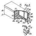
- Figure 1 is an exploded perspective view of a printer head for use with the ink tank according to the present invention.
- An ink tank 2 is detachably mounted by a holder on top of a printer head body 1.
- the ink tank 2 is of a double construction composed of an air tank 2b for containing a black ink and an ink tank 2a which is divided into three sections for coloured inks.
- the inks are impregnated in ink-impregnated members 61, 62 ( Figure 2) of a porous material which are contained in the ink tank 2.
- the printer head body 1 has in its front portion an ink supply guide 12 (Figure 2) having ink guide grooves 12b with ends leading to the respective ink-impregnated member 62 and a wire guide 13 ( Figure 4) having a wire guide hole 13a for guiding the tip or distal end portion of a respective printing wire (not shown) therein.
- the ink supply guide 12 and the wire guide 13 which form no part of the present invention jointly form an ink path from the ink tank 2 to the distal end portion of the wire.
- the printer head shown in Figures 1 and 2 is adapted for use in a four-colour printer plotter or in a four-colour image printer, and four wires are employed respectively corresponding to the four colours.
- the distal end portion of the wire is located rearwardly of a distal end surface 13c ( Figure 4) of the wire guide 13, and the length of the wire is selected such that an ink meniscus formed in a front portion of the wire guide hole 13a covers the distal end of the wire.
- An ink guide assembly which comprises the ink supply guide 12 and the wire guide 13, will be described in greater detail with reference to Figure 4.
- An ink supply guide 12" has a central hole 12"f for guiding the distal end portion of the wire.
- the ink supply guide 12" also has an axial ink guide groove 12"b leading to the ink-impregnated member 62.
- the ink guide groove 12"b has a width and a depth selected such that ink will be stably supplied from the ink tank 2 as described later on.
- the ink supply guide 12" has on a front surface 12" thereof a circular groove 12"a which communicates with the ink guide groove 12"b through an inner portion (not shown).
- the wire guide 13 has a proximal end 13d thereof placed in the circular groove 12"a. There is only a small gap between the wire and the peripheral surface defining the wire guide hole 13a in the wire guide 13. The ink is guided from the ink tank 2 through the ink guide grooves 12b, 12"b in the ink supply guide 12, 12" and through the wire guide 13 to the distal end portion of the wire under capillary attraction.
- the ink tank 2 or each ink tank 2a, 2b, comprises an ink tank body 40, two stacked ink-impregnated members 61, 62 of a porous material which are disposed in the space in the ink tank body 40 so as to fill the latter, and a lid 50.
- the ink-impregnated members 61, 62 are impregnated with ink under a pressure lower than atmospheric pressure ranging from 5 to 10 mmHg, so that air remaining in the porous ink-impregnated members will be reduced as much as possible to increase the amount of impregnated ink.
- the ink tank body 40 has a bottom 40a provided with a front ink supply port 41 and a front wall 40b having an air hole 42 defined in a stepped portion thereof.
- the ink supply guide 12 has an arm 12d which is inserted in the ink supply port 41 and which projects from the printer head body 1.
- the bottom 40a of the ink tank body 40 has a raised surface 44 in which there are a plurality of slots 45a, 45b, 45c which communicate with the ink supply port 41.
- the slots 45a, 45b, 45c are disposed opposite to and communicate with the ink supply grooves 12b provided in the arm 12d of the ink supply guide 12. Although not shown, the slots 45a, 45b are joined together to form a single slot which together with the slot 45c guides the ink into the ink supply grooves 12b.
- the ink tank body 40 also has a side wall 40c having on its inner wall a plurality of vertical ridges 47 having lower ends held against the bottom 40a and upper ends kept out of contact with the tank lid 50.
- the ink tank body 40 further has a front partition 48 which is disposed behind the air hole 42 and in front of the ink supply port 41, the front partition 48 having one end joined to the side wall 40c.
- the tank lid 50 has on a lower surface thereof a plurality of longitudinal ridges 51.
- the space or hollow interior defined by the bottom 40a, the sidewall 40c, the partition 48, and the lid 50 of the tank body 50 accommodates therein the two porous members 61, 62 as double layers which are held in contact with only the raised surface 44 of the bottom 40a, the vertical ridges 47 of the sidewall 40c, the partition 48, and the ridges 51 of the lid 50.
- the porous members 61, 62 have different average hole sizes or diameters.
- the porous member 61, which has a larger average hole diameter, is placed on top of the other porous member 62.
- the porous member 62 which is closer to the ink supply port 41, is made of a porous material having a smaller average hole diameter than that of the porous member 61, while the porous member 61, which is further from the ink supply port 41 has a greater average hole diameter than that of the porous member 62.
- the capillary attraction is successively greater along the ink path, that is, successively from the porous member 61 having the larger average hole diameter to the porous member 62 having the smaller average hole diameter and thence to the ink guide slots 45a, 45b, 45c provided in the raised surface 44 of the bottom 40a of the ink tank body 40 and so to the ink guide grooves 12b provided in the ink supply guide arm 12d and hence to the gaps between the ink supply guide 12 and the wire guide 13, and finally to the gap between the ink supply guide 12 and the wire and the gap between the wire guide 12 and the wire.
- the above capillary attraction setting can be achieved by providing the following dimensions: The average hole diameter of the porous member 61 0.4 mm.
- the average hole diameter of the porous member 62 0.3 mm.
- the width of each of the ink guide slots 45a, 45b, 45c 0.12 mm The width of the ink guide grooves 12b 0.1 mm
- the gaps between the ink supply guide 12 and the wire guide 13 0.1 mm The gap between the surface defining the wire guide hole 13a and the wire 0.01 mm.
- the printer head body 1 has a head frame 30 including side walls extending from upper and back portions of the printer head body 1 and serving as a holder support 31.
- Each of the side walls of the holder support 31 has a holder support hole 32, a leaf spring 36 which is defined by two vertical recesses 33a, 33b in the holder support 31 and which has a holder attachment hole 34, and a guide slot 35,.
- a holder 70a has on each of its opposite sides a cylindrical projection 71a, which is rotatably mounted in a holder support hole 32 in the head frame 30, and a semispherical projection 72a, which is engageable in a holder attachment hole 34.
- Each of the ink tanks 2a, 2b has a side disposed closer to the respective holder support 31 and having a cylindrical projection 49 engageable with a lower edge of the respective guide slot 35.
- the ink tank 2 can be attached to the holder 70a and detached therefrom in the following manner.
- the holder 70a is supported in the position shown in Figure 3, and the ink tank 2 is inserted into the holder 70a in the direction of the arrow C. At this time, the ink tank 2 is not required to be accurately positioned in the holder 70a and hence can easily be inserted into the holder 70a. Then, the holder 70a is turned in the direction of the arrow D to bring the projection 49 on each of the sides of the ink tank 2 into contact with an edge of the respective guide slot 35 in the head frame 30, whereupon the ink tank 2 is positioned with respect to the head frame 30.
- the ink supply port 41 is now positioned correctly above the arm 12d of the ink supply guide 12 which projects upwardly from the printer head body 1.
- the arm 12d engages in the ink support port 41 and be inserted into the ink tank 2.
- the semispherical projection 72a on each side of the tank holder 70a engages and spreads the leaf springs 36 apart from each other.
- the semispherical projections 72a finally engage in the attachment holes 34 in the leaf springs 36, whereupon the leaf springs 36 return to the vertical positions to retain the holder 70a securely in position.
- the ink guide slots 45a, 45b, 45c in the bottom 40a of the ink tank 2 are disposed opposite to the ink guide grooves 12b in the arm 12d of the ink supply guide 12, thus forming part of the ink path from the ink tank 2 to the printer head body 1.
- the ink tank 2 can be removed in a procedure which is the reverse of the attachment process described above.
- the distal end of the wire projects through the ink meniscus, carries ink thereon, and hits a sheet of print paper (not shown) to transfer the ink to the print paper.
- a sheet of print paper (not shown) to transfer the ink to the print paper.
- any excessive ink on the distal end surface 13c of the wire guide 13 is drawn under capillary attraction into cross-sectionally V-shaped collection grooves 13b ( Figure 3) provided in the front and side surfaces of the wire guide 13 and is returned to the ink supply guide 12 without smearing the print paper.
- the grooves 13b are thus provided in the distal end surface of the wire guide 13 and communicate with the wire guide hole 13a. As shown in Figure 3, the grooves 13b extend to the outer periphery of the wire guide 13 so as to be open to the atmosphere.
- the wire guide hole 13a should have a proper dimension in the vicinity of the distal end of the wire and a proper amount of ink, without either an excess or a shortage of ink, should be supplied from the ink tank 2.
- the ink guide path from the ink tank 2 to a position in the vicinity of the distal end of the wire is composed of slots, grooves, and gaps.
- the-amount of ink necessary for printing can be guided to the distal end of the wire under appropriate capillary attraction without causing an overflow.
- the gaps between the wire guide 13 and the ink supply guide 12 can be dimensioned to retain ink therein under capillary attraction, an appropriate quantity of ink can be supplied even when the ink supply from the ink supply grooves 12b is reduced due to increased use of ink.
- the dimensions of the ink supply grooves and gaps, the hole diameters of the porous members 61, 62 and the widths of the slots 45a, 45b, 45c are selected so that the capillary attraction is progressively greater along the ink path. Therefore, ink will not be interrupted in the ink path as described below.
- the ink is consumed from the ink tank 2 as printing progresses. Ink flows from the porous member 62 through the ink guide grooves 12b, or through the ink guide grooves 12b and the slots 45a, 45b, 45c, into the printer head body 1. Since the ink moves transversely across the porous member 62 at this time, the distance that the ink moves through the porous member 62 is small and no ink interruption occurs. When ink in the porous member 62 is consumed, a pressure difference immediately occurs between the ink in the porous member 61 and the ink in the porous member 62 due to the difference between their average hole diameters, and the same quantity of ink as is consumed is supplied from the porous member 61 to the porous member 62.
- the ink guide mechanism in the printer head body operates to produce the same advantage. If the flow of ink is interrupted in the ink path by reason of vibrations or the like, a mass of ink which has been so interrupted is moved forward until it is joined to a preceding mass of ink since the capillary attraction is greater in the ink path than in the ink tank. Since the capillary attraction is greater in the vicinity of the distal end of the wire than in the portion of the ink path in which the flow of ink is interrupted, no ink is retracted from the distal end of the wire, and hence the dot density will not be rendered unstable even momentarily, so that all ink on the distal end of the wire can be used up.
- the ink-impregnated members 61, 62 are supported on the ridges 47, 51 in the ink tank body 40.
- the ink-impregnated members 61, 62 are therefore surrounded by a layer of air which communicates by way of the air hole 42 with the ambient air. Since the ink is impregnated under a low pressure, there is substantially no air layer or pocket enclosed by the ink in the ink-impregnated members 61, 62. Therefore, any expansion of the air in the tank 2 caused by a temperature rise or by a reduction in atmospheric pressure is released through the air hole 42, so that the pressure in the tank 2 is equalized to atmospheric pressure and does not force the ink out of the ink tank 2.
- the ink tank 2 is therefore protected from an ink outflow due to variations in temperature and atmospheric pressure, and is capable of supplying ink stably.
- the ink tank 2 and the ink guide path for supplying ink to the wire have dimensions dependent on the accuracy of the shapes of the components. Since the components can be easily formed with high dimensional accuracy, as by moulding, the ink tank 2 and and ink guide path can be highly dimensionalloy accurate and have a stable ink supply capability.
- the ink tank 2 and the ink guide path can easily be assembled as they are composed of a small number of parts. They may be maintained free from wear and deformation for a long period of use and can keep their initial performance partly because of the lubrication effected by the ink.
- Figure 4 is an exploded perspective view of a further version of an ink guide member 12".
- the ink guide member 12" has an ink guide groove 12"b in which is mounted an ink guide porous member 12e which serves as an extension of the ink-impregnated members in the ink tank.
- the operation of the ink guide member 12" is essentially the same as that of the previous embodiment.
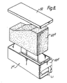
- FIG 8 is an exploded perspective view of a further embodiment of an ink tank 2" according to the present invention.
- the parts of the ink tank of Figure 8 other than a porous member 60" are the same as those in the embodiment shown in Figure 2.
- the porous member 60" has different front and rear thicknesses so that the thicker front portion, which is disposed adjacent to the ink supply port 41, is compressed by the tank lid 50 when the porous member 60" is introduced into the tank body 40.
- the porous member 60" has uniform hole diameters, the front portion thereof, which is adjacent to the ink supply port 41, has a smaller average hole diameter, with the hole diameter becoming progressively greater toward the rear portion, which is remote from the ink supply port 41, at the time when the porous member 60" is placed in the ink tank body 40.
- the porous member 60" is structurally equivalent to a plurality of porous sheet layers of different average hole diameters which are placed in the ink tank body 40 with the average hole diameters becoming progressively greater from the front to rear portion of the member 60". Therefore, the operation of the porous member 60" is basically the same as that of the porous members 61, 62 shown in Figure 4.
- the ink tank 2 is placed above the printer head 1, the ink tank 2 may be located below the wires to achieve a stable printing density through the ink guiding process described above,.
- ink can be stably supplied through a simple construction from an ink tank to the distal end of a wire, and ink is stably attached to the distal end of the wire for producing a stable and proper ink dot density.
- the ink will not be interrupted in the ink guide path and the risk of a supply failure will be reduced.
- the quantity of ink absorbed in the ink guide path is smaller than would be the case with a known arrangement in which a porous member is used to apply ink to the distal end of the wire. Therefore, any wasted ink which is not used for printing is of a small quantity, and hence substantially all the ink in the ink tank can effectively be used for printing.
- a fresh cartridge ink tank can be mounted in place so that fresh ink can immediately be supplied to the distal end of the wire for resuming the desired printing operation.
- the described ink supply system is simple in construction, it takes up only a small space.
- the ink supply systems for different ink colours can be spaced widely so that any unwanted colour mixing can be avoided.
Claims (4)
- Réservoir d'encre destiné à la transmission d'une quantité convenable d'encre nécessaire à une tête d'imprimante matricielle, le réservoir d'encre (2) ayant un couvercle, une paroi rectangulaire de fond et des parois s'étendant entre elles, et un canal d'alimentation en encre (41) destiné à distribuer de l'encre, et contenant un dispositif d'absorption d'encre qui comporte au moins un organe poreux (60" ; 61, 62) dont les pores ont une dimension qui diminue progressivement vers le canal de transmission d'encre (41), dans lequel le canal de transmission d'encre (41) est placé dans la paroi de fond (40a), près d'un petit côté de la paroi rectangulaire de fond (40a), et plusieurs fentes (45a, 45b, 45c) communiquant avec le canal de transmission d'encre sont placées à l'intérieur de la paroi de fond.
- Réservoir d'encre selon la revendication 1, caractérisé en ce que le dispositif d'absorption d'encre (60") a une partie inclinée.
- Réservoir d'encre selon la revendication 1 ou 2, caractérisé en ce que l'organe d'absorption d'encre (60") a une partie plus épaisse au voisinage du canal de transmission d'encre (41).
- Réservoir d'encre selon l'une quelconque des revendications précédentes, caractérisé en ce que l'organe d'absorption d'encre est comprimé au voisinage de l'orifice de transmission d'encre.
Priority Applications (1)
| Application Number | Priority Date | Filing Date | Title |
|---|---|---|---|
| EP96115079A EP0749839A3 (fr) | 1984-05-22 | 1984-10-09 | Réservoir d'encre |
Applications Claiming Priority (8)
| Application Number | Priority Date | Filing Date | Title |
|---|---|---|---|
| JP102843/84 | 1984-05-22 | ||
| JP102841/84 | 1984-05-22 | ||
| JP59102843A JP2563769B2 (ja) | 1984-05-22 | 1984-05-22 | プリンタのインクタンク |
| JP10284384 | 1984-05-22 | ||
| JP10284184 | 1984-05-22 | ||
| JP10284184A JPS60245560A (ja) | 1984-05-22 | 1984-05-22 | プリンタのインクタンク |
| EP90201874A EP0406983B1 (fr) | 1984-05-22 | 1984-10-09 | Réservoir d'encre pour une tête d'impression matricielle par points à aguilles |
| EP84306887A EP0139508B1 (fr) | 1983-10-13 | 1984-10-09 | Tête d'impression par points à matrice de fils |
Related Parent Applications (2)
| Application Number | Title | Priority Date | Filing Date |
|---|---|---|---|
| EP90201874A Division EP0406983B1 (fr) | 1984-05-22 | 1984-10-09 | Réservoir d'encre pour une tête d'impression matricielle par points à aguilles |
| EP90201874.6 Division | 1984-10-09 |
Related Child Applications (1)
| Application Number | Title | Priority Date | Filing Date |
|---|---|---|---|
| EP96115079A Division EP0749839A3 (fr) | 1984-05-22 | 1984-10-09 | Réservoir d'encre |
Publications (3)
| Publication Number | Publication Date |
|---|---|
| EP0605388A2 EP0605388A2 (fr) | 1994-07-06 |
| EP0605388A3 EP0605388A3 (en) | 1994-07-27 |
| EP0605388B1 true EP0605388B1 (fr) | 2001-03-14 |
Family
ID=26443529
Family Applications (10)
| Application Number | Title | Priority Date | Filing Date |
|---|---|---|---|
| EP90201874A Expired - Lifetime EP0406983B1 (fr) | 1984-05-22 | 1984-10-09 | Réservoir d'encre pour une tête d'impression matricielle par points à aguilles |
| EP94101083A Expired - Lifetime EP0605388B1 (fr) | 1984-05-22 | 1984-10-09 | Réservoir d'encre |
| EP94101089A Expired - Lifetime EP0605389B1 (fr) | 1984-05-22 | 1984-10-09 | Réservoir d'encre |
| EP94101088A Expired - Lifetime EP0615848B1 (fr) | 1984-05-22 | 1984-10-09 | Réservoir d'encre |
| EP94101074A Revoked EP0614761B1 (fr) | 1984-05-22 | 1984-10-09 | Réservoir d'encre |
| EP90201873A Expired - Lifetime EP0406982B1 (fr) | 1984-05-22 | 1984-10-09 | Procédé d'imprégnation d'absorbeurs d'encre |
| EP94101081A Expired - Lifetime EP0605386B1 (fr) | 1984-05-22 | 1984-10-09 | Réservoir d'encre |
| EP90201876A Expired - Lifetime EP0398453B1 (fr) | 1984-05-22 | 1984-10-09 | Réservoir d'encre pour une tête d'impression matricielle par points à aguilles |
| EP94101082A Revoked EP0605387B1 (fr) | 1984-05-22 | 1984-10-09 | Procédé d'imprégnation d'absorbeurs d'encre dans un réservoir d'encre |
| EP96115079A Withdrawn EP0749839A3 (fr) | 1984-05-22 | 1984-10-09 | Réservoir d'encre |
Family Applications Before (1)
| Application Number | Title | Priority Date | Filing Date |
|---|---|---|---|
| EP90201874A Expired - Lifetime EP0406983B1 (fr) | 1984-05-22 | 1984-10-09 | Réservoir d'encre pour une tête d'impression matricielle par points à aguilles |
Family Applications After (8)
| Application Number | Title | Priority Date | Filing Date |
|---|---|---|---|
| EP94101089A Expired - Lifetime EP0605389B1 (fr) | 1984-05-22 | 1984-10-09 | Réservoir d'encre |
| EP94101088A Expired - Lifetime EP0615848B1 (fr) | 1984-05-22 | 1984-10-09 | Réservoir d'encre |
| EP94101074A Revoked EP0614761B1 (fr) | 1984-05-22 | 1984-10-09 | Réservoir d'encre |
| EP90201873A Expired - Lifetime EP0406982B1 (fr) | 1984-05-22 | 1984-10-09 | Procédé d'imprégnation d'absorbeurs d'encre |
| EP94101081A Expired - Lifetime EP0605386B1 (fr) | 1984-05-22 | 1984-10-09 | Réservoir d'encre |
| EP90201876A Expired - Lifetime EP0398453B1 (fr) | 1984-05-22 | 1984-10-09 | Réservoir d'encre pour une tête d'impression matricielle par points à aguilles |
| EP94101082A Revoked EP0605387B1 (fr) | 1984-05-22 | 1984-10-09 | Procédé d'imprégnation d'absorbeurs d'encre dans un réservoir d'encre |
| EP96115079A Withdrawn EP0749839A3 (fr) | 1984-05-22 | 1984-10-09 | Réservoir d'encre |
Country Status (4)
| Country | Link |
|---|---|
| EP (10) | EP0406983B1 (fr) |
| DE (9) | DE3486480T2 (fr) |
| HK (3) | HK73295A (fr) |
| SG (7) | SG26404G (fr) |
Families Citing this family (5)
| Publication number | Priority date | Publication date | Assignee | Title |
|---|---|---|---|---|
| JP3582592B2 (ja) | 2001-04-03 | 2004-10-27 | セイコーエプソン株式会社 | インクカートリッジ、及びインクジェット記録装置 |
| KR0145341B1 (ko) * | 1992-07-24 | 1998-07-15 | 미타라이 하지메 | 잉크카트리지, 잉크제트기록조립뭉치 및 잉크제트기록장치 |
| US6332675B1 (en) | 1992-07-24 | 2001-12-25 | Canon Kabushiki Kaisha | Ink container, ink and ink jet recording apparatus using ink container |
| CA2290700C (fr) | 1992-07-24 | 2004-08-31 | Canon Kabushiki Kaisha | Reservoir a encre, encre et appareil d'enregistrement a jet d'encre utilisant ce reservoir |
| GB2395684B (en) † | 2002-11-26 | 2005-06-08 | Seiko Epson Corp | Ink cartridge and recording apparatus |
Citations (1)
| Publication number | Priority date | Publication date | Assignee | Title |
|---|---|---|---|---|
| FR2229320A5 (en) * | 1973-05-09 | 1974-12-06 | Meci Materiel Elect Contr | Continuous inking device for pen recorders - has reservoir containing cellular material to contain ink |
Family Cites Families (19)
| Publication number | Priority date | Publication date | Assignee | Title |
|---|---|---|---|---|
| US3491685A (en) * | 1967-05-24 | 1970-01-27 | Pitney Bowes Inc | Rotatable ink storage and metering cartridge |
| US3863686A (en) * | 1972-10-16 | 1975-02-04 | V Mark Automation Ltd | Apparatus and process for article filling under reduced pressure |
| US3858703A (en) * | 1973-01-05 | 1975-01-07 | Centronics Data Computer | Bidirectional dual head printer |
| US4095237A (en) * | 1974-12-26 | 1978-06-13 | Aktiebolaget Electrolux | Ink jet printing head |
| DE2546835C3 (de) * | 1975-10-18 | 1980-11-06 | Philips Patentverwaltung Gmbh, 2000 Hamburg | Druckeinrichtung mit in Längsrichtung verschiebbaren Drucknadeln |
| DE2704735C2 (de) * | 1977-02-04 | 1982-08-05 | Siemens AG, 1000 Berlin und 8000 München | Auslaufsicherer Tintenvorratsbehälter |
| JPS55150372A (en) * | 1979-05-11 | 1980-11-22 | Seiko Epson Corp | Printer |
| US4279519A (en) * | 1979-06-01 | 1981-07-21 | Centronics Data Computer Corp. | Dot matrix printing device employing novel image transfer technique for printing on single ply or multiple ply print receiving media |
| GB2063175B (en) * | 1979-11-06 | 1984-02-15 | Shinshu Seiki Kk | Ink jet printer |
| DE3171562D1 (en) * | 1980-06-06 | 1985-09-05 | Epson Corp | Ink supply system for a printer |
| EP0042293B1 (fr) * | 1980-06-17 | 1986-06-11 | Seiko Epson Corporation | Imprimante par points avec un fil |
| JPS57100088A (en) * | 1980-12-15 | 1982-06-22 | Seiko Epson Corp | Ink jet type printer |
| IT1145242B (it) * | 1981-12-23 | 1986-11-05 | Olivetti & Co Spa | Testina di stampa a getto d inchiostro e relativa stampante seriale |
| DE3207074A1 (de) * | 1982-02-26 | 1983-09-15 | Siemens AG, 1000 Berlin und 8000 München | Schreibelement mit piezoantrieb fuer registrier- und aufzeichnungsgeraete |
| JPS58194550A (ja) * | 1982-05-10 | 1983-11-12 | Canon Inc | インクカセット |
| US4437104A (en) * | 1982-05-10 | 1984-03-13 | Advanced Color Technology, Inc. | Ink disposal system for ink jet printer |
| US4511906A (en) * | 1982-10-13 | 1985-04-16 | Sharp Kabushiki Kaisha | Ink liquid reservoir in an ink jet system printer |
| DE3484840D1 (de) * | 1983-10-13 | 1991-08-29 | Seiko Epson Corp | Punktdruckkopf mit nadelmatrix. |
| JPS60192672A (ja) * | 1984-03-14 | 1985-10-01 | Janome Sewing Mach Co Ltd | プリンタのインク含浸プラテン |
-
1984
- 1984-10-09 EP EP90201874A patent/EP0406983B1/fr not_active Expired - Lifetime
- 1984-10-09 DE DE3486480T patent/DE3486480T2/de not_active Expired - Lifetime
- 1984-10-09 EP EP94101083A patent/EP0605388B1/fr not_active Expired - Lifetime
- 1984-10-09 EP EP94101089A patent/EP0605389B1/fr not_active Expired - Lifetime
- 1984-10-09 SG SG1995906848A patent/SG26404G/en unknown
- 1984-10-09 DE DE3486482T patent/DE3486482T2/de not_active Expired - Lifetime
- 1984-10-09 EP EP94101088A patent/EP0615848B1/fr not_active Expired - Lifetime
- 1984-10-09 DE DE3486335T patent/DE3486335T2/de not_active Expired - Lifetime
- 1984-10-09 EP EP94101074A patent/EP0614761B1/fr not_active Revoked
- 1984-10-09 DE DE3486334T patent/DE3486334C5/de not_active Expired - Lifetime
- 1984-10-09 DE DE3486337T patent/DE3486337T2/de not_active Expired - Lifetime
- 1984-10-09 EP EP90201873A patent/EP0406982B1/fr not_active Expired - Lifetime
- 1984-10-09 EP EP94101081A patent/EP0605386B1/fr not_active Expired - Lifetime
- 1984-10-09 SG SG1995907218A patent/SG26412G/en unknown
- 1984-10-09 EP EP90201876A patent/EP0398453B1/fr not_active Expired - Lifetime
- 1984-10-09 SG SG1996006357A patent/SG64344A1/en unknown
- 1984-10-09 SG SG1995906830A patent/SG26403G/en unknown
- 1984-10-09 EP EP94101082A patent/EP0605387B1/fr not_active Revoked
- 1984-10-09 SG SG1996006751A patent/SG54266A1/en unknown
- 1984-10-09 SG SG1996006312A patent/SG52578A1/en unknown
- 1984-10-09 DE DE3486485T patent/DE3486485T2/de not_active Expired - Lifetime
- 1984-10-09 DE DE3486483T patent/DE3486483T2/de not_active Expired - Lifetime
- 1984-10-09 SG SG1996006337A patent/SG46589A1/en unknown
- 1984-10-09 DE DE3486487T patent/DE3486487T2/de not_active Expired - Lifetime
- 1984-10-09 DE DE3486481T patent/DE3486481T2/de not_active Revoked
- 1984-10-09 EP EP96115079A patent/EP0749839A3/fr not_active Withdrawn
-
1995
- 1995-05-11 HK HK73295A patent/HK73295A/xx not_active IP Right Cessation
- 1995-05-11 HK HK73395A patent/HK73395A/xx not_active IP Right Cessation
- 1995-05-11 HK HK73495A patent/HK73495A/xx not_active IP Right Cessation
Patent Citations (1)
| Publication number | Priority date | Publication date | Assignee | Title |
|---|---|---|---|---|
| FR2229320A5 (en) * | 1973-05-09 | 1974-12-06 | Meci Materiel Elect Contr | Continuous inking device for pen recorders - has reservoir containing cellular material to contain ink |
Also Published As
Similar Documents
| Publication | Publication Date | Title |
|---|---|---|
| EP0139508B1 (fr) | Tête d'impression par points à matrice de fils | |
| US5156472A (en) | Dot matrix printer supply system having ink absorbing member filled under reduced pressure | |
| US6123469A (en) | Ink-supply wire dot matrix printer head | |
| US5156473A (en) | Multi-color cartridge ink-supply system for a dot matrix printer | |
| US5221148A (en) | Dot matrix printer ink supply system having ink absorbing member substantially filling an ink tank | |
| US5174665A (en) | Ink-supply system for a dot matrix printer | |
| US6247803B1 (en) | Ink jet recording apparatus and method for replenishing ink in the tank cartridge | |
| US5156470A (en) | Two cartridge ink-supply system for a multi-color dot matrix printer | |
| AU691954B2 (en) | Ink-supplied printer and ink supply tank | |
| EP0605388B1 (fr) | Réservoir d'encre | |
| EP0614762B1 (fr) | Réservoir d'encre | |
| US6474798B1 (en) | Ink supplied printer head and ink container | |
| US5570963A (en) | Ink transfer roller for ribbon cartridges | |
| JPH04226368A (ja) | プリンタのインク供給機構 |
Legal Events
| Date | Code | Title | Description |
|---|---|---|---|
| PUAI | Public reference made under article 153(3) epc to a published international application that has entered the european phase |
Free format text: ORIGINAL CODE: 0009012 |
|
| PUAL | Search report despatched |
Free format text: ORIGINAL CODE: 0009013 |
|
| 17P | Request for examination filed |
Effective date: 19940125 |
|
| AC | Divisional application: reference to earlier application |
Ref document number: 406983 Country of ref document: EP |
|
| AK | Designated contracting states |
Kind code of ref document: A2 Designated state(s): DE FR GB IT NL |
|
| RHK1 | Main classification (correction) |
Ipc: B41J 3/12 |
|
| AK | Designated contracting states |
Kind code of ref document: A3 Designated state(s): DE FR GB IT NL |
|
| 17Q | First examination report despatched |
Effective date: 19960124 |
|
| GRAG | Despatch of communication of intention to grant |
Free format text: ORIGINAL CODE: EPIDOS AGRA |
|
| RIC1 | Information provided on ipc code assigned before grant |
Free format text: 7B 41J 2/255 A, 7B 41J 2/305 B, 7B 41J 2/175 B |
|
| RTI1 | Title (correction) |
Free format text: INK TANK |
|
| GRAG | Despatch of communication of intention to grant |
Free format text: ORIGINAL CODE: EPIDOS AGRA |
|
| GRAH | Despatch of communication of intention to grant a patent |
Free format text: ORIGINAL CODE: EPIDOS IGRA |
|
| GRAH | Despatch of communication of intention to grant a patent |
Free format text: ORIGINAL CODE: EPIDOS IGRA |
|
| GRAA | (expected) grant |
Free format text: ORIGINAL CODE: 0009210 |
|
| AC | Divisional application: reference to earlier application |
Ref document number: 406983 Country of ref document: EP Ref document number: 139508 Country of ref document: EP |
|
| AK | Designated contracting states |
Kind code of ref document: B1 Designated state(s): DE FR GB IT NL |
|
| XX | Miscellaneous (additional remarks) |
Free format text: TEILANMELDUNG 96115079.4 EINGEREICHT AM 19/09/96. |
|
| ITF | It: translation for a ep patent filed |
Owner name: BUZZI, NOTARO&ANTONIELLI D'OULX |
|
| REF | Corresponds to: |
Ref document number: 3486482 Country of ref document: DE Date of ref document: 20010419 |
|
| ET | Fr: translation filed | ||
| REG | Reference to a national code |
Ref country code: GB Ref legal event code: IF02 |
|
| PLBQ | Unpublished change to opponent data |
Free format text: ORIGINAL CODE: EPIDOS OPPO |
|
| PLBI | Opposition filed |
Free format text: ORIGINAL CODE: 0009260 |
|
| 26 | Opposition filed |
Opponent name: PELIKAN HARDCOPY(INTERNATIONAL) AG Effective date: 20011214 |
|
| PLBF | Reply of patent proprietor to notice(s) of opposition |
Free format text: ORIGINAL CODE: EPIDOS OBSO |
|
| NLR1 | Nl: opposition has been filed with the epo |
Opponent name: PELIKAN HARDCOPY(INTERNATIONAL) AG |
|
| PLBF | Reply of patent proprietor to notice(s) of opposition |
Free format text: ORIGINAL CODE: EPIDOS OBSO |
|
| PGFP | Annual fee paid to national office [announced via postgrant information from national office to epo] |
Ref country code: FR Payment date: 20031003 Year of fee payment: 20 |
|
| PGFP | Annual fee paid to national office [announced via postgrant information from national office to epo] |
Ref country code: NL Payment date: 20031008 Year of fee payment: 20 Ref country code: GB Payment date: 20031008 Year of fee payment: 20 |
|
| PGFP | Annual fee paid to national office [announced via postgrant information from national office to epo] |
Ref country code: DE Payment date: 20031016 Year of fee payment: 20 |
|
| PLCK | Communication despatched that opposition was rejected |
Free format text: ORIGINAL CODE: EPIDOSNREJ1 |
|
| APBP | Date of receipt of notice of appeal recorded |
Free format text: ORIGINAL CODE: EPIDOSNNOA2O |
|
| APBQ | Date of receipt of statement of grounds of appeal recorded |
Free format text: ORIGINAL CODE: EPIDOSNNOA3O |
|
| PG25 | Lapsed in a contracting state [announced via postgrant information from national office to epo] |
Ref country code: GB Free format text: LAPSE BECAUSE OF EXPIRATION OF PROTECTION Effective date: 20041008 |
|
| PG25 | Lapsed in a contracting state [announced via postgrant information from national office to epo] |
Ref country code: NL Free format text: LAPSE BECAUSE OF EXPIRATION OF PROTECTION Effective date: 20041009 |
|
| REG | Reference to a national code |
Ref country code: GB Ref legal event code: PE20 |
|
| NLV7 | Nl: ceased due to reaching the maximum lifetime of a patent |
Effective date: 20041009 |
|
| APAA | Appeal reference recorded |
Free format text: ORIGINAL CODE: EPIDOS REFN |
|
| PLAQ | Examination of admissibility of opposition: information related to despatch of communication + time limit deleted |
Free format text: ORIGINAL CODE: EPIDOSDOPE2 |
|
| PLAR | Examination of admissibility of opposition: information related to receipt of reply deleted |
Free format text: ORIGINAL CODE: EPIDOSDOPE4 |
|
| PLBQ | Unpublished change to opponent data |
Free format text: ORIGINAL CODE: EPIDOS OPPO |
|
| PLAB | Opposition data, opponent's data or that of the opponent's representative modified |
Free format text: ORIGINAL CODE: 0009299OPPO |
|
| R26 | Opposition filed (corrected) |
Opponent name: PELIKAN HARDCOPY(INTERNATIONAL) AG Effective date: 20011214 |
|
| APBU | Appeal procedure closed |
Free format text: ORIGINAL CODE: EPIDOSNNOA9O |
|
| PLBN | Opposition rejected |
Free format text: ORIGINAL CODE: 0009273 |
|
| STAA | Information on the status of an ep patent application or granted ep patent |
Free format text: STATUS: OPPOSITION REJECTED |
|
| APAH | Appeal reference modified |
Free format text: ORIGINAL CODE: EPIDOSCREFNO |
|
| 27O | Opposition rejected |
Effective date: 20050608 |
|
| PLAB | Opposition data, opponent's data or that of the opponent's representative modified |
Free format text: ORIGINAL CODE: 0009299OPPO |