EP0615511B1 - Carrier for stacked articles - Google Patents
Carrier for stacked articles Download PDFInfo
- Publication number
- EP0615511B1 EP0615511B1 EP93922362A EP93922362A EP0615511B1 EP 0615511 B1 EP0615511 B1 EP 0615511B1 EP 93922362 A EP93922362 A EP 93922362A EP 93922362 A EP93922362 A EP 93922362A EP 0615511 B1 EP0615511 B1 EP 0615511B1
- Authority
- EP
- European Patent Office
- Prior art keywords
- articles
- carrier
- panel
- separator sheet
- cans
- Prior art date
- Legal status (The legal status is an assumption and is not a legal conclusion. Google has not performed a legal analysis and makes no representation as to the accuracy of the status listed.)
- Expired - Lifetime
Links
Images


Classifications
-
- B—PERFORMING OPERATIONS; TRANSPORTING
- B65—CONVEYING; PACKING; STORING; HANDLING THIN OR FILAMENTARY MATERIAL
- B65D—CONTAINERS FOR STORAGE OR TRANSPORT OF ARTICLES OR MATERIALS, e.g. BAGS, BARRELS, BOTTLES, BOXES, CANS, CARTONS, CRATES, DRUMS, JARS, TANKS, HOPPERS, FORWARDING CONTAINERS; ACCESSORIES, CLOSURES, OR FITTINGS THEREFOR; PACKAGING ELEMENTS; PACKAGES
- B65D71/00—Bundles of articles held together by packaging elements for convenience of storage or transport, e.g. portable segregating carrier for plural receptacles such as beer cans or pop bottles; Bales of material
- B65D71/70—Trays provided with projections or recesses in order to assemble multiple articles, e.g. intermediate elements for stacking
-
- B—PERFORMING OPERATIONS; TRANSPORTING
- B65—CONVEYING; PACKING; STORING; HANDLING THIN OR FILAMENTARY MATERIAL
- B65D—CONTAINERS FOR STORAGE OR TRANSPORT OF ARTICLES OR MATERIALS, e.g. BAGS, BARRELS, BOTTLES, BOXES, CANS, CARTONS, CRATES, DRUMS, JARS, TANKS, HOPPERS, FORWARDING CONTAINERS; ACCESSORIES, CLOSURES, OR FITTINGS THEREFOR; PACKAGING ELEMENTS; PACKAGES
- B65D5/00—Rigid or semi-rigid containers of polygonal cross-section, e.g. boxes, cartons or trays, formed by folding or erecting one or more blanks made of paper
- B65D5/42—Details of containers or of foldable or erectable container blanks
- B65D5/44—Integral, inserted or attached portions forming internal or external fittings
- B65D5/46—Handles
- B65D5/46072—Handles integral with the container
- B65D5/46088—Handles integral with the container formed by extensions of closure flaps, by closure flaps or by extensions of side flaps of a container formed by folding a blank to form a tubular body
-
- B—PERFORMING OPERATIONS; TRANSPORTING
- B65—CONVEYING; PACKING; STORING; HANDLING THIN OR FILAMENTARY MATERIAL
- B65D—CONTAINERS FOR STORAGE OR TRANSPORT OF ARTICLES OR MATERIALS, e.g. BAGS, BARRELS, BOTTLES, BOXES, CANS, CARTONS, CRATES, DRUMS, JARS, TANKS, HOPPERS, FORWARDING CONTAINERS; ACCESSORIES, CLOSURES, OR FITTINGS THEREFOR; PACKAGING ELEMENTS; PACKAGES
- B65D71/00—Bundles of articles held together by packaging elements for convenience of storage or transport, e.g. portable segregating carrier for plural receptacles such as beer cans or pop bottles; Bales of material
- B65D71/06—Packaging elements holding or encircling completely or almost completely the bundle of articles, e.g. wrappers
- B65D71/12—Packaging elements holding or encircling completely or almost completely the bundle of articles, e.g. wrappers the packaging elements, e.g. wrappers being formed by folding a single blank
- B65D71/36—Packaging elements holding or encircling completely or almost completely the bundle of articles, e.g. wrappers the packaging elements, e.g. wrappers being formed by folding a single blank having a tubular shape, e.g. tubular wrappers, with end walls
-
- B—PERFORMING OPERATIONS; TRANSPORTING
- B65—CONVEYING; PACKING; STORING; HANDLING THIN OR FILAMENTARY MATERIAL
- B65D—CONTAINERS FOR STORAGE OR TRANSPORT OF ARTICLES OR MATERIALS, e.g. BAGS, BARRELS, BOTTLES, BOXES, CANS, CARTONS, CRATES, DRUMS, JARS, TANKS, HOPPERS, FORWARDING CONTAINERS; ACCESSORIES, CLOSURES, OR FITTINGS THEREFOR; PACKAGING ELEMENTS; PACKAGES
- B65D2571/00—Bundles of articles held together by packaging elements for convenience of storage or transport, e.g. portable segregating carrier for plural receptacles such as beer cans, pop bottles; Bales of material
- B65D2571/00123—Bundling wrappers or trays
- B65D2571/00129—Wrapper locking means
- B65D2571/00135—Wrapper locking means integral with the wrapper
- B65D2571/00141—Wrapper locking means integral with the wrapper glued
-
- B—PERFORMING OPERATIONS; TRANSPORTING
- B65—CONVEYING; PACKING; STORING; HANDLING THIN OR FILAMENTARY MATERIAL
- B65D—CONTAINERS FOR STORAGE OR TRANSPORT OF ARTICLES OR MATERIALS, e.g. BAGS, BARRELS, BOTTLES, BOXES, CANS, CARTONS, CRATES, DRUMS, JARS, TANKS, HOPPERS, FORWARDING CONTAINERS; ACCESSORIES, CLOSURES, OR FITTINGS THEREFOR; PACKAGING ELEMENTS; PACKAGES
- B65D2571/00—Bundles of articles held together by packaging elements for convenience of storage or transport, e.g. portable segregating carrier for plural receptacles such as beer cans, pop bottles; Bales of material
- B65D2571/00123—Bundling wrappers or trays
- B65D2571/00432—Handles or suspending means
- B65D2571/00456—Handles or suspending means integral with the wrapper
- B65D2571/00469—Straps made between two handholes
-
- B—PERFORMING OPERATIONS; TRANSPORTING
- B65—CONVEYING; PACKING; STORING; HANDLING THIN OR FILAMENTARY MATERIAL
- B65D—CONTAINERS FOR STORAGE OR TRANSPORT OF ARTICLES OR MATERIALS, e.g. BAGS, BARRELS, BOTTLES, BOXES, CANS, CARTONS, CRATES, DRUMS, JARS, TANKS, HOPPERS, FORWARDING CONTAINERS; ACCESSORIES, CLOSURES, OR FITTINGS THEREFOR; PACKAGING ELEMENTS; PACKAGES
- B65D2571/00—Bundles of articles held together by packaging elements for convenience of storage or transport, e.g. portable segregating carrier for plural receptacles such as beer cans, pop bottles; Bales of material
- B65D2571/00123—Bundling wrappers or trays
- B65D2571/00432—Handles or suspending means
- B65D2571/00518—Handles or suspending means with reinforcements
- B65D2571/00524—Handles or suspending means with reinforcements integral
-
- B—PERFORMING OPERATIONS; TRANSPORTING
- B65—CONVEYING; PACKING; STORING; HANDLING THIN OR FILAMENTARY MATERIAL
- B65D—CONTAINERS FOR STORAGE OR TRANSPORT OF ARTICLES OR MATERIALS, e.g. BAGS, BARRELS, BOTTLES, BOXES, CANS, CARTONS, CRATES, DRUMS, JARS, TANKS, HOPPERS, FORWARDING CONTAINERS; ACCESSORIES, CLOSURES, OR FITTINGS THEREFOR; PACKAGING ELEMENTS; PACKAGES
- B65D2571/00—Bundles of articles held together by packaging elements for convenience of storage or transport, e.g. portable segregating carrier for plural receptacles such as beer cans, pop bottles; Bales of material
- B65D2571/00123—Bundling wrappers or trays
- B65D2571/00432—Handles or suspending means
- B65D2571/00537—Handles or suspending means with stress relieving means
- B65D2571/00549—Handles or suspending means with stress relieving means consisting of fold lines
-
- B—PERFORMING OPERATIONS; TRANSPORTING
- B65—CONVEYING; PACKING; STORING; HANDLING THIN OR FILAMENTARY MATERIAL
- B65D—CONTAINERS FOR STORAGE OR TRANSPORT OF ARTICLES OR MATERIALS, e.g. BAGS, BARRELS, BOTTLES, BOXES, CANS, CARTONS, CRATES, DRUMS, JARS, TANKS, HOPPERS, FORWARDING CONTAINERS; ACCESSORIES, CLOSURES, OR FITTINGS THEREFOR; PACKAGING ELEMENTS; PACKAGES
- B65D2571/00—Bundles of articles held together by packaging elements for convenience of storage or transport, e.g. portable segregating carrier for plural receptacles such as beer cans, pop bottles; Bales of material
- B65D2571/00123—Bundling wrappers or trays
- B65D2571/00648—Elements used to form the wrapper
- B65D2571/00654—Blanks
- B65D2571/0066—Blanks formed from one single sheet
-
- B—PERFORMING OPERATIONS; TRANSPORTING
- B65—CONVEYING; PACKING; STORING; HANDLING THIN OR FILAMENTARY MATERIAL
- B65D—CONTAINERS FOR STORAGE OR TRANSPORT OF ARTICLES OR MATERIALS, e.g. BAGS, BARRELS, BOTTLES, BOXES, CANS, CARTONS, CRATES, DRUMS, JARS, TANKS, HOPPERS, FORWARDING CONTAINERS; ACCESSORIES, CLOSURES, OR FITTINGS THEREFOR; PACKAGING ELEMENTS; PACKAGES
- B65D2571/00—Bundles of articles held together by packaging elements for convenience of storage or transport, e.g. portable segregating carrier for plural receptacles such as beer cans, pop bottles; Bales of material
- B65D2571/00123—Bundling wrappers or trays
- B65D2571/00709—Shape of the formed wrapper, i.e. shape of each formed element if the wrapper is made from more than one element
- B65D2571/00722—Shape of the formed wrapper, i.e. shape of each formed element if the wrapper is made from more than one element tubular with end walls, e.g. walls not extending on the whole end surface
- B65D2571/00728—Shape of the formed wrapper, i.e. shape of each formed element if the wrapper is made from more than one element tubular with end walls, e.g. walls not extending on the whole end surface the end walls being closed by gluing
-
- B—PERFORMING OPERATIONS; TRANSPORTING
- B65—CONVEYING; PACKING; STORING; HANDLING THIN OR FILAMENTARY MATERIAL
- B65D—CONTAINERS FOR STORAGE OR TRANSPORT OF ARTICLES OR MATERIALS, e.g. BAGS, BARRELS, BOTTLES, BOXES, CANS, CARTONS, CRATES, DRUMS, JARS, TANKS, HOPPERS, FORWARDING CONTAINERS; ACCESSORIES, CLOSURES, OR FITTINGS THEREFOR; PACKAGING ELEMENTS; PACKAGES
- B65D2571/00—Bundles of articles held together by packaging elements for convenience of storage or transport, e.g. portable segregating carrier for plural receptacles such as beer cans, pop bottles; Bales of material
- B65D2571/00123—Bundling wrappers or trays
- B65D2571/00808—Inserts
- B65D2571/00814—Inserts for reinforcing
-
- Y—GENERAL TAGGING OF NEW TECHNOLOGICAL DEVELOPMENTS; GENERAL TAGGING OF CROSS-SECTIONAL TECHNOLOGIES SPANNING OVER SEVERAL SECTIONS OF THE IPC; TECHNICAL SUBJECTS COVERED BY FORMER USPC CROSS-REFERENCE ART COLLECTIONS [XRACs] AND DIGESTS
- Y10—TECHNICAL SUBJECTS COVERED BY FORMER USPC
- Y10S—TECHNICAL SUBJECTS COVERED BY FORMER USPC CROSS-REFERENCE ART COLLECTIONS [XRACs] AND DIGESTS
- Y10S206/00—Special receptacle or package
- Y10S206/821—Stacking member
Definitions
- This invention relates to an article carrier according to the preamble of claim 1. More particularly, it relates to a carrier which is adapted to carry a plurality of layers of articles in stacked end-to-end relationship.
- Sleeve-type carriers are commonly used to package beverarge cans and other types of articles, and are typically formed from paperboard blanks which have been folded into collapsed sleeve form. Each collapsed sleeve is opened by a packaging machine, after which cans or other articles are introduced through one or both of the open ends of the sleeve and the end panel flaps are folded and secured together.
- the cans are normally introduced in upright position while the carrier sleeve is supported on one of its side panels, with the open ends of the sleeve facing out to recieve the cans.
- the resulting carrier therefore contains a layer of cans the ends of which are located adjacent the side panels of the carrier. Additionally, a handle is normally incorporated into the top panel of the carrier to facilitate lifting and carrying.
- the inventive carrier includes a separator sheet between the layers of articles, the specific design of which is laid down in the characterizing portion of claim 1.
- the bottom ends of articles in an upper layer and the top ends of articles in the next lower layer are aligned in end-to-end relationship and contact portions of the separator sheet. That portions of the separator sheet contacted by the bottom ends of articles of the upper layer are below the primary plane of the separator sheet.
- One method of fabrication involving the inventive type of separator sheet employs a sheet having distortable portions which overlie the tops of the articles in the lower layer.
- the sheet is placed on the top ends of articles in a lower layer and a group of similar articles are placed on the separator sheet to form an upper layer, with the bottom ends of the articles in the upper layer contacting the distortable portions of the separator sheet.
- the stacked layers then become part of a carrier, as by introducing them into a carrier sleeve through an open end of the sleeve.
- the invention is particularly applicable to articles capable of being nested, such as beverage cans wherein one end is narrower than the other and the wider end is of recessed construction.
- articles capable of being nested such as beverage cans wherein one end is narrower than the other and the wider end is of recessed construction.
- the distortable portions of the separator sheet include transverse panel portions connected to the separator sheet by a fold line, with spaced slits extending inwardly from the fold line to divide the transverse panel portions into segments.
- the top panel of the carrier preferably is comprised of an inner flap connected to the upper edge of one of the side panels along a fold line and an outer flap connected to the upper edge of the other side panel.
- each of the inner and outer flaps has an edge remote from the side panels and each flap contains a handle opening spaced from the remote edge thereof.
- the outer flap overlaps the inner flap to form an area of double thickness extending between the handle openings.
- Reinforcing means are provided in the area of double thickness for reinforcing the area against tearing, and stress relief lines are provided in the top panel extending outwardly from the handle openings to distribute lifting stresses.
- the stress relief lines comprise score lines extending from each handle opening to the nearest side panel, preferably to the corners of the top panel, and the reinforcing means comprises a sheet adhered to one of the top panel flaps, the sheet including a folded edge substantially aligned with a side edge of the handle opening in the outer top panel flap.
- the end panels are comprised of end flaps foldably connected to the top, bottom and side panels, the end flap connected to the top panel comprising two overlapped flaps segments, whereby the overlapped flaps comprise an extension of the overlapped top panel flaps.
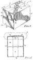
- the carrier Due to the stacked arrangement of the articles in the carrier, the carrier is of a shape and size which makes lifting by means of the handle a relatively simple task, even though the contents of the carrier may be quite heavy.
- the carrier 10 is comprised of side panels 12 foldably connected to top panel 14 and to the bottom panel, not visible in this view.
- the top panel is comprised of two top panel flaps 16 and 18, described more fully below.
- End panels 20 connect the top, bottom and side panels and are comprised of end panel flaps 22 and 24 adhered to dust flaps 26 and 28, wherein the end panel flaps are foldably connected to the top and bottom panels and the dust flaps are foldably connected to the side panels.
- Spaced handle openings 30 and 32 are provided in the top panel and extend along the length of the carrier substantially parallel to the side panels.
- Score lines 34 extend from the ends of handle opening 30 to the nearest corners of the carrier, while score lines 36 extend from the ends of handle opening 32 to the other corners of the carrier.
- the carrier contains a bottom layer of articles, shown for purpose of illustration as beverage cans C1, and an upper layer of articles, shown as cans C2, in stacked relationship.
- the lower ends of the upper cans C2 thus are supported on the upper ends of the bottom cans C1, with the bottom cans resting on the bottom panel 38.
- the top panel 14 is closely adjacent, and preferably is in contact with, the tops of the cans C2 to provide for a tight fit between the cans and the carrier.
- the top layer of cans is made up of twelve cans arranged in three rows of four cans. Since the bottom layer is identically arranged, the total number of cans in the carrier is twenty-four.
- the top panel is reinforced between the handle openings as indicated by numeral 40, the details of which are explained hereinafter.
- the carrier 10 of FIG. 1 is formed from the blank 42, wherein portions corresponding to similar elements of the carrier are identified by the same reference numerals.
- the blank 42 is a single sheet of material, preferably paperboard, comprising a centrally located bottom panel section 38 connected to the side panel sections 12 along fold lines 44.
- the outer top panel flap 16 is connected to one of the side panel sections 12 along fold line 46, while the inner top panel flap 18 is connected to the other side panel section 12 along fold line 48.
- End panel flaps 24 are connected to the bottom panel section 38 along fold lines 50, and end panel flaps 22 are connected to the outer and inner top panel flaps 16 and 18 along fold lines 52 and 54, respectively.
- Inner or dust flaps 26 and 28 are connected to the side panel sections 12 along fold lines 55 and 57, respectively.
- the reinforcing means 40 of FIG. 2 comprises a sheet adhered to the inner top panel flap 18 so as to terminate at the free edge 56 of the inner top panel flap. It is preferred that the reinforcing sheet entirely cover the area which includes the handle opening 32, requiring the sheet to have a corresponding cutout 58 to enable the fingers of a user to penetrate the top panel when lifting the carrier, but in any event the sheet should at least extend to the outer edge of the cutout 32 in order to provide extra thickness in the handle strap portion. It will be appreciated that the inner surface of the blank is facing the viewer in FIG. 4 and that the reinforcing sheet is on the inner surface of the inner top panel flap.
- Fabrication of the carrier is by standard means, with the blank being folded along the fold lines 44, 46 and 48 to bring the top panel flaps 16 and 18 together and then overlapping and gluing the top panel flaps in the stippled area 60 of the blank of FIG. 4.
- the end panel flaps 22 extending from the outer top panel flap 16 are thus adhered to the end panel flaps 22 extending from the inner top panel flap 18 to form the upper end panel flaps extending from the top panel.
- the end panels are formed in the usual manner by first folding the dust flaps 26 and 28 and then the end panel flaps down and gluing the end panel flaps to the dust flaps.
- the reinforcing sheet 40 preferably is comprised of a thinner sheet than the material from which the carrier is formed, and is folded over upon itself to provide a fold 62.
- the fold 62 is aligned with the edge 56 of the inner top panel flap 18, and both are aligned with the inner edge 64 of the cutout 30.
- This edge is referred to in the claims as the remote side edge of the cutout 30, referring to the arrangement whereby this edge of the cutout is farthest from the side panel to which the inner top panel flap 18 is connected.
- This design strengthens the strap portion due to the extra thickness of material in this region and also prevents tearing along the cutout edge 64 as well as in areas of the top panel flap 16 which would normally be at risk to a tear originating at this critical juncture in the handle area. This is thought to be due to the fact that a fold acts as a surface rather than an edge, and just as it is considerably more difficult to initiate a tear at a surface than at an edge, the folded reinforcement strip makes it difficult to initiate a tear along this lifting edge of the handle opening.
- This design additionally provides a cushioning effect for the hand of a user. For purpose of illustration the thickness of the carrier material has been exaggerated.
- the design of the invention anticipates upward movement of the top panel as the fingers pull up on the handle while first gripping the strap portion and during lifting and carrying.
- the top panel is adapted to smoothly bow upwardly without tearing at critical areas which normally receive most of the lifting stresses. This is accomplished by the stress relief score lines 34 and 36 which extend from the ends of the handle cutouts to the side panels. Preferably, as illustrated, these lines extend to the corners of the package, thereby transmitting the lifting stresses to the corner folds.
- the benefit of the carrier design of the invention can be better understood by comparing a carrier of the invention which is adapted to carry 24 standard 12-fluid ounce beverage cans to a sleeve-type carrier adapted to carry only 12 of the same cans.
- the cans are arranged with their ends against the side panels in three rows of four cans each.
- the length of the package is thus approximately equal to four can diameters, the height to three can diameters and the width to one can length.
- the cans are arranged with their ends against the top and bottom panels in two stacked layers, each layer being made up of three rows of four cans each.
- the length of this package is thus approximately equal to four can diameters, the same as the length of the prior art 12-can package.
- the height of the package is approximately equal to two can lengths and the width of the package is approximately equal to three can diameters. In terms of actual dimensions, this would mean that for a package of the same length as the prior art 12-pack package, a height of only about two inches more and a width of less than three inches more results in twice the carrying capacity. Additional layers of cans or other articles could be packaged simply by making the height of the carrier an additional article length greater.
- the handle reinforcement afforded by the suitcase type of handle illustrated in the preferred embodiment resists tearing in this critical area, and the stress relief lines distribute the lifting and carrying stresses from the handle area to the sides, preferably to the corner folds of the carrier.
- the overlapped portion of the top panel extends beyond the handle area to the ends of the top panel and beyond the top panel through the upper end panel flaps connected to the top panel. This increases the strength of the end panel flaps which in turn increases the strength of the end panels, allowing them to better resist the lifting stresses which may be distributed to them via the stress relief lines.
- a divider or separator sheet between the layers in order to prevent direct contact between the ends of stacked cans has been found to be preferred.
- a single planar sheet of paperboard When a single planar sheet of paperboard is used as a separator sheet, it may remain in planar form in the carrier or the downward forces produced by stacked packages or stacked pallets may cause the cans in the upper layer of a package to be moved down sufficiently to compress the engaged portions of the paperboard sheet. The resulting slightly lower position of the upper cans may create a gap between the tops of the cans in the upper layer and the top panel of the carrier, resulting in some loosening in the package. However, this is normally tolerable and the low cost of the single sheet suggests this is at this time a preferred construction.
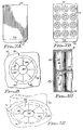
- a planar sheet suitable for use in the invention which is illustrated in FIG. 7A at reference numeral 69, is of a size to cover the adjacent ends of cans in the upper and lower layers.
- the sheet 69 includes at least one end strip 71 which is delineated by fold line 73 for a purpose explained below.
- the invention may employ a separator sheet which permits the bottom edges of the upper cans to nest within the recessed upper portions of the lower cans.
- the sheet 70 is a sheet of paperboard or other suitable compressible and flexible material and may contain a number of circular areas 72 capable of being distorted from the plane of the sheet and designed to be positioned between the ends of stacked cans.
- the illustrated sheet contains twelve distortable areas designed for use in a package holding twenty-four cans, obviously the sheet can be designed for use with any number of cans.
- the sheet 70 like the sheet 69, includes an end strip 74 similar to the end strip 71, which is delineated by fold line 76 for a purpose explained below.
- each area 72 comprises an outer circular fold line 78, a smaller concentric circular fold line 80 and a still smaller concentric circular cutout 82.
- a number of regularly spaced slits 84 extend from the outer fold line 78 radially inwardly, preferably terminating a short distance from the cutout 82.
- the area defined by the outer and inner fold lines 78 and 80 and successive slits 84 are transverse panel portions 83, while the area defined by the inner fold line 80, the cutout 82, and successive slits 84, whether or not the slits extend completely to the cutout, are additional panel portions 85.
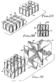
- the sheet 70 is placed on top of an assembled group of cans C1, which are arranged as they would be in a package, so that each distortable area 72 of the sheet overlies the upper end of a can C1 in the lower layer.
- An assembled group of cans C2 is then moved into place so as to form an upper layer of cans resting on the areas 72 and thus being aligned with the cans in the lower layer.
- the group of cans C2 is moved laterally onto the lower layer, sliding over the separator sheet 70.
- the end strip 74 extends beyond the end cans in the lower layer and is gripped or held in place by any suitable means, not shown, in order to stabilize the sheet while the cans of the upper layer are sliding over it.
- a smooth edge is presented to the cans C2 of the upper layer. If this smooth edge were not presented, the cans C2 might "trip" over the raw edge of a divider sheet lacking the end strip 74 and become too unstable to load into the sleeve 10. Note that the same situation exists with respect to sheet 69, and that the end strip 71 is folded down about fold line 73 in the same manner as explained in connection with end strip 74.
- the sheet 70 by terminating the slits 84 short of the circular cutout 82, a generally smooth surface is presented to the sliding cans of the upper layer. If the slits 84 extend out to the circular cutout, the edges of the resulting wedge-shaped tabs may act as an obstruction to movement of the upper layer of cans, snagging them and interfering with the rapid formation of a carrier package.
- the lower layer of cans C1 will be placed in the sleeve 10 with the separator sheet 69 or 70 on top of the cans C1. Then, the cans C2 will be loaded into the sleeve 10 by being pushed over the separator sheet.
- the separator sheet would require two end flaps. As illustrated in FIG. 10, the end flap 74 is folded down about the fold line 76, and is in contact with the end panel after formation of the carrier. This would also be the case with the end flap 71 of the sheet 69.
- FIGS. 8, 11A, 11B and 12 The relative positions of the upper and lower cans C2 and C1 and the separator sheet 70 are best shown in FIG. 11A, where the bottom rim 90 of the can C2 can be seen to be supported on the transverse panel portions 83 of the distortable area 72 and the separator sheet is supported on the upper rim or chime 92 of the can.
- the can C1 is illustrated as being of typical construction, with the upper end 94 being recessed with respect to the rim 92 and also carrying a pull tab 96.
- this aspect of the invention permits separator sheets of economical thickness to be employed while at the same time providing for reliable protection against damage to or marring of the cans.
- separator sheets has been described primarily in connection with the packaging of beverage cans, it will be understood that this aspect of the invention may be employed with other types of articles whose shape permits nesting of the article ends as described above.
Abstract
Description
Claims (7)
- An article carrier (10) containing a plurality of layers of stacked articles (C1, C2) comprising:a bottom panel (38) upon which the lowermost of said layer of stacked articles rests;a top panel (14) positioned above the uppermost of said layers of stacked articles;a pair of opposed side panels (12), integrally connected to and extending between said bottom panel (38) and said top panel (14), said side panels (12) enclosing two sides of said layers of stacked articles;a pair of opposed end panels (20) extending between said bottom panel (38) and said top panel (14) substantially perpendicular to said side panels (12) and connected to said bottom (38) and top (14) panels to thereby complete the enclosure of said layers of stacked articles;a separator sheet (70) between adjacent layers of articles (C1, C2), the separator sheet being generally disposed in a primary plane generally parallel to said bottom (38) and top (14) panels;the articles (C1, C2) in each layer having top and bottom ends contacting portions of the separator sheet (70), the articles in each layer being aligned in end-to-end relationship with the articles in the adjacent layer, the bottom ends of the articles adjacent the separator being narrower than the top ends of the articles in the adjacent layer, said top ends of the articles being recessed; andthe portions (72) of the separator sheet (70) contacted by the bottom ends of articles being below the primary plane of the separator sheet (70), the bottom ends of the adjacent articles and the portions of the separator sheet extending into the recess,
characterized in thatthose portions of the separator sheet (70) extending into the recesses include transverse panel portions (83) connected to the separator sheet (70) by a first fold line (78) and additional panel portions (85) connected to the transverse panel portions by a second fold line (80) wherein slits (84) extend inwardly from the first fold line (78) to divide the transverse panel portions (83) and the additional panel portions (85) into segments. - The article carrier of claim 1, wherein the carrier contains two layers of stacked articles.
- The article carrier of claim 1, wherein the separator sheet (70) includes an end flap (74) extending transversely of the sheet (70) and engaging an interior face of an end panel (20).
- The article carrier of claim 1, wherein the articles have circular peripheries and the first fold line (78) is circular.
- The article carrier of claim 4, wherein the articles are beverage cans.
- The article carrier of claim 1, including a cutout (82) centrally located in the additional panel portions (85).
- The article carrier of claim 6, wherein the slits (84) terminate short of the cutout (82).
Applications Claiming Priority (3)
| Application Number | Priority Date | Filing Date | Title |
|---|---|---|---|
| US07/958,882 US5246113A (en) | 1992-02-11 | 1992-10-09 | Carrier for stacked articles |
| US958882 | 1992-10-09 | ||
| PCT/US1993/009062 WO1994008868A1 (en) | 1992-10-09 | 1993-09-24 | Carrier for stacked articles |
Publications (3)
| Publication Number | Publication Date |
|---|---|
| EP0615511A1 EP0615511A1 (en) | 1994-09-21 |
| EP0615511A4 EP0615511A4 (en) | 1996-04-10 |
| EP0615511B1 true EP0615511B1 (en) | 1998-07-22 |
Family
ID=25501407
Family Applications (1)
| Application Number | Title | Priority Date | Filing Date |
|---|---|---|---|
| EP93922362A Expired - Lifetime EP0615511B1 (en) | 1992-10-09 | 1993-09-24 | Carrier for stacked articles |
Country Status (15)
| Country | Link |
|---|---|
| US (1) | US5246113A (en) |
| EP (1) | EP0615511B1 (en) |
| JP (1) | JPH07502004A (en) |
| AT (1) | ATE168647T1 (en) |
| AU (1) | AU671312B2 (en) |
| BR (1) | BR9305638A (en) |
| CA (1) | CA2124823C (en) |
| DE (1) | DE69319885T2 (en) |
| ES (1) | ES2118259T3 (en) |
| MY (1) | MY109938A (en) |
| NO (1) | NO942130D0 (en) |
| NZ (1) | NZ256604A (en) |
| TR (1) | TR28416A (en) |
| WO (1) | WO1994008868A1 (en) |
| ZA (1) | ZA937232B (en) |
Families Citing this family (97)
| Publication number | Priority date | Publication date | Assignee | Title |
|---|---|---|---|---|
| US5282348A (en) * | 1992-06-16 | 1994-02-01 | Riverwood International Corporation | Clip-type article carrier and method of manufacture |
| TW221401B (en) * | 1993-03-01 | 1994-03-01 | Riverwood Int Corp | Stacked article cartoning apparatus |
| TW210324B (en) * | 1993-03-25 | 1993-08-01 | Riverwood Int Corp | Stacked article packaging method |
| DK0694014T3 (en) | 1993-04-19 | 2000-04-17 | Mead Corp | Carton with separating plate for packaging for two layers of cans |
| US5297725A (en) * | 1993-07-01 | 1994-03-29 | Riverwood International Corporation | Carrier for stacked articles |
| US5427242A (en) * | 1993-08-31 | 1995-06-27 | The Mead Corporation | Two tier can package having secured divider panel and method of forming the same |
| ZA947021B (en) * | 1993-09-17 | 1995-05-02 | Riverwood Int Corp | Method of forming a stacked article group |
| US5437143A (en) * | 1993-09-20 | 1995-08-01 | The Mead Corporation | Method of forming a package of beverage cans |
| US5447299A (en) * | 1994-02-04 | 1995-09-05 | Riverwood International Corporation | Divider sheet for stacked products and method of supplying planar articles |
| US5518111A (en) * | 1994-03-02 | 1996-05-21 | The Mead Corporation | Removable divider panel for multiple-tier article package |
| US5439111A (en) * | 1994-05-05 | 1995-08-08 | Illinois Tool Works Inc. | Package comprising containers in unitized upper and lower tiers with folded divider |
| US5437370A (en) * | 1994-05-05 | 1995-08-01 | Illinois Tool Works Inc. | Package comprising containers in unitized upper and lower tiers |
| GB9413864D0 (en) * | 1994-07-08 | 1994-08-24 | Mead Corp | Packaging machinery |
| GB9413865D0 (en) * | 1994-07-08 | 1994-08-24 | Mead Corp | Carton and divider panel |
| US6394272B1 (en) | 1994-07-08 | 2002-05-28 | The Mead Corporation | Carton and divider panel |
| GB9416623D0 (en) * | 1994-08-17 | 1994-10-12 | Riverwood Int Ltd | Separating arrangement for cans |
| DK0776298T3 (en) * | 1994-08-17 | 1998-10-07 | Riverwood Int Corp | Separator plate for stacked cans |
| US5711419A (en) * | 1994-08-17 | 1998-01-27 | International Paper | Paperboard bottle carrier |
| US5579911A (en) * | 1994-11-17 | 1996-12-03 | Werth; Elmer D. | Detachable side by side multi-unit package |
| US5682984A (en) * | 1995-01-19 | 1997-11-04 | The C.W. Zumbiel Co. | Two tier can carton |
| US5636753A (en) * | 1995-03-16 | 1997-06-10 | Wilkinson; Dennis | Stabilizer for plural drum stacks |
| US5869519A (en) * | 1996-12-16 | 1999-02-09 | Idun Pharmaceuticals, Inc. | C-terminal modified (n-substituted)-2-indolyl dipeptides as inhibitors of the ICE/ced-3 family of cysteine proteases |
| US6184244B1 (en) | 1996-12-16 | 2001-02-06 | Idun Pharmaceuticals, Inc. | C-terminal modified (N-substituted)-2-indolyl dipeptides as inhibitors of the ICE/ced-3 family of cysteine proteases |
| US5877197A (en) * | 1996-12-16 | 1999-03-02 | Karanewsky; Donald S. | C-terminal modified (N-substituted)-2-indolyl dipeptides as inhibitors of the ICE/ced-3 family of cysteine proteases |
| DE19803144A1 (en) * | 1998-01-28 | 1999-07-29 | 4 P Nicolaus Kempten Gmbh | Cardboard blank for the production of multi-piece packaging |
| US6649654B1 (en) * | 1999-11-23 | 2003-11-18 | The Regents Of The University Of California | Methods for identifying and using IKK inhibitors |
| US6918487B2 (en) * | 2003-02-12 | 2005-07-19 | Graphic Packaging International, Inc. | Dispensing system for double stack carton |
| GB0326435D0 (en) * | 2003-11-13 | 2003-12-17 | Graphic Packaging Int Inc | Dispensing package |
| US7089871B2 (en) * | 2003-12-01 | 2006-08-15 | Covalence Specialty Materials Corp. | Tier sheet |
| US7093713B2 (en) * | 2004-01-30 | 2006-08-22 | Graphic Packaging International, Inc. | Fully enclosed pack with interlocking separator pad and dispenser |
| US7195118B2 (en) * | 2004-01-30 | 2007-03-27 | Graphic Packaging International, Inc. | Beveled corner carton with an interlocking separator pad |
| US7240789B2 (en) * | 2004-02-03 | 2007-07-10 | Graphic Packaging International, Inc. | Carton with an interlocking separator pad and dispenser |
| WO2006086597A1 (en) * | 2005-02-11 | 2006-08-17 | Graphic Packaging International, Inc. | Carton with interlocking divider |
| US8020695B2 (en) | 2007-01-23 | 2011-09-20 | Graphic Packaging International, Inc. | Basket carrier |
| WO2009006096A2 (en) | 2007-06-29 | 2009-01-08 | Graphic Packaging International, Inc. | Carton with divider |
| ES2425887T3 (en) * | 2008-12-16 | 2013-10-17 | Graphic Packaging International, Inc. | Support element for containers |
| US8387784B2 (en) * | 2009-02-24 | 2013-03-05 | Graphic Packaging International, Inc. | Package for containers |
| EP2401208A4 (en) | 2009-02-24 | 2013-11-20 | Graphic Packaging Int Inc | Package for containers |
| AU2010217927B2 (en) | 2009-02-27 | 2013-05-23 | Graphic Packaging International, Inc. | Carrier for containers |
| ES2452240T3 (en) | 2009-06-23 | 2014-03-31 | Graphic Packaging International, Inc. | Cardboard box with handle |
| BR112012018357A2 (en) * | 2010-02-12 | 2019-09-24 | Graphic Packaging Int Inc | carrier to accommodate a plurality of containers, blanket to form a carrier to accommodate a plurality of containers, and method for forming a carrier |
| ES2612478T3 (en) | 2010-05-19 | 2017-05-17 | Graphic Packaging International, Inc. | Container for containers |
| JP5721830B2 (en) | 2010-07-30 | 2015-05-20 | グラフィック パッケージング インターナショナル インコーポレイテッド | Container holding carrier |
| US8631932B2 (en) | 2010-12-03 | 2014-01-21 | Graphic Packaging International, Inc. | Chime-engaging package for containers |
| US8701878B2 (en) | 2011-05-13 | 2014-04-22 | Graphic Packaging International, Inc. | Package for beverage containers |
| US8955674B2 (en) | 2011-08-05 | 2015-02-17 | Graphic Packaging International, Inc. | Package for containers |
| CN104220343B (en) | 2012-03-29 | 2016-03-16 | 印刷包装国际公司 | The assembly set of carton blank and tray blank, carton and form the method for carton |
| US9284090B2 (en) | 2012-07-09 | 2016-03-15 | Graphic Packaging International, Inc. | Divider for package |
| BR112015020335A2 (en) | 2013-03-15 | 2017-07-18 | Graphic Packaging Int Inc | container for containing a food product, mold for forming a container for containing a food product, and method for forming a container for containing a food product |
| EP3060493A1 (en) | 2013-10-25 | 2016-08-31 | Graphic Packaging International, Inc. | Carton with retention features |
| WO2015095120A1 (en) | 2013-12-16 | 2015-06-25 | Graphic Packaging International, Inc. | Construct with stiffening features |
| US9669976B2 (en) | 2014-04-11 | 2017-06-06 | Graphic Packaging International, Inc. | Container clip for engaging at least one container |
| CA2947296C (en) | 2014-05-09 | 2018-11-20 | Graphic Packaging International, Inc. | Basket style carrier with divider flap |
| MX2017006908A (en) | 2014-12-01 | 2017-08-28 | Graphic Packaging Int Inc | Carrier for containers. |
| WO2016106116A1 (en) | 2014-12-23 | 2016-06-30 | Graphic Packaging International, Inc. | Carrier for containers |
| WO2016178853A1 (en) * | 2015-05-01 | 2016-11-10 | Westrock Packaging Systems, Llc | Enclosed top stacks |
| WO2016201046A1 (en) | 2015-06-11 | 2016-12-15 | Graphic Packaging International, Inc. | Carton with divider |
| US10017293B2 (en) | 2015-07-29 | 2018-07-10 | Graphic Packaging International, Llc | Modular carton |
| US10301090B2 (en) | 2015-12-01 | 2019-05-28 | Graphic Packaging International, Llc | Carrier for containers |
| EP3400179A4 (en) | 2016-01-05 | 2019-06-12 | Graphic Packaging International, LLC | Carrier for containers |
| BR112019012968B1 (en) | 2017-02-17 | 2023-03-28 | Graphic Packaging International, Llc | CARRIER FOR CONDITIONING AT LEAST ONE CONTAINER, BLANKET FOR FORMING A CARRIER FOR CONDITIONING AT LEAST ONE CONTAINER, AND METHOD FOR FORMING A CONVEYOR FOR CONDITIONING AT LEAST ONE CONTAINER |
| CN110891873B (en) * | 2017-05-19 | 2022-02-18 | 维实洛克包装系统有限公司 | Carton and carton blank |
| USD878931S1 (en) | 2017-07-20 | 2020-03-24 | Graphic Packaging International, Llc | Carrier for containers |
| USD886640S1 (en) | 2017-07-20 | 2020-06-09 | Graphic Packaging International, Llc | Carrier for containers |
| USD872597S1 (en) | 2017-08-09 | 2020-01-14 | Graphic Packaging International, Llc | Carrier for containers |
| US10766680B2 (en) | 2017-08-09 | 2020-09-08 | Graphic Packaging International, Llc | Carrier for containers |
| BE1026374B1 (en) * | 2018-06-15 | 2020-01-22 | Anheuser Busch Inbev Sa | Portable cooling multipack |
| BE1026443B1 (en) * | 2018-07-06 | 2020-02-03 | Anheuser Busch Inbev Sa | GUIDANCE COMPOSITION FOR SECONDARY PACKAGING |
| CN112789223A (en) | 2018-09-07 | 2021-05-11 | 印刷包装国际有限责任公司 | Package for a container |
| USD878932S1 (en) | 2018-10-12 | 2020-03-24 | Graphic Packaging International, Llc | Carrier |
| USD883803S1 (en) | 2018-10-12 | 2020-05-12 | Graphic Packaging International, Llc | Carrier |
| US11261013B2 (en) | 2018-12-14 | 2022-03-01 | Graphic Packaging International, Llc | Carrier for containers |
| US11027904B2 (en) | 2018-12-14 | 2021-06-08 | Graphic Packaging International, Llc | Carrier for containers |
| US11180301B2 (en) | 2018-12-14 | 2021-11-23 | Graphic Packaging International, Llc | Carrier for containers |
| USD946420S1 (en) | 2020-06-30 | 2022-03-22 | Graphic Packaging International, Llc | Carrier |
| US11014727B2 (en) | 2018-12-14 | 2021-05-25 | Graphic Packaging International, Llc | Carrier for containers |
| USD946419S1 (en) | 2020-06-30 | 2022-03-22 | Graphic Packaging International, Llc | Carrier |
| USD946421S1 (en) | 2018-12-14 | 2022-03-22 | Graphic Packaging International, Llc | Carrier |
| US11623803B2 (en) | 2018-12-14 | 2023-04-11 | Graphic Packaging International, Llc | Carrier for containers |
| USD946416S1 (en) | 2019-05-30 | 2022-03-22 | Graphic Packaging International, Llc | Carrier |
| USD974923S1 (en) | 2019-05-30 | 2023-01-10 | Graphic Packaging International, Llc | Carrier |
| USD984279S1 (en) | 2019-05-30 | 2023-04-25 | Graphic Packaging International, Llc | Carrier |
| USD984280S1 (en) | 2019-05-30 | 2023-04-25 | Graphic Packaging International, Llc | Carrier |
| CA3143259C (en) | 2019-07-18 | 2023-10-03 | Graphic Packaging International, Llc | Carton with attachment features |
| AU2020435468A1 (en) | 2020-03-13 | 2022-10-06 | Jorge Fundador HERRERA MUÑOZ | Carrier device for grouping and transporting a set of beverage cans |
| USD984281S1 (en) | 2020-04-27 | 2023-04-25 | Graphic Packaging International, Llc | Carrier |
| USD946417S1 (en) | 2020-06-30 | 2022-03-22 | Graphic Packaging International, Llc | Carrier |
| USD946418S1 (en) | 2020-04-27 | 2022-03-22 | Graphic Packaging International, Llc | Carrier |
| CA3180955A1 (en) | 2020-05-22 | 2021-11-25 | Graphic Packaging International, Llc | Carrier with lid |
| USD972942S1 (en) | 2020-06-04 | 2022-12-20 | Graphic Packaging International, Llc | Carrier with lid |
| CA3197671A1 (en) | 2020-09-30 | 2022-04-07 | Graphic Packaging International, Llc | Carrier for containers |
| USD1000290S1 (en) | 2021-03-24 | 2023-10-03 | Graphic Packaging International, Llc | Carrier for containers |
| USD983049S1 (en) | 2021-03-24 | 2023-04-11 | Graphic Packaging International, Llc | Carrier for containers |
| USD984266S1 (en) | 2021-03-24 | 2023-04-25 | Graphic Packaging International, Llc | Carrier for containers |
| USD984282S1 (en) | 2021-03-24 | 2023-04-25 | Graphic Packaging International, Llc | Carrier for containers |
| BR112023023220A2 (en) | 2021-06-09 | 2024-01-30 | Graphic Packaging Int Llc | CONVEYOR FOR CONTAINING A PLURALITY OF CONTAINERS, BULL PART FOR FORMING A CONVEYOR FOR CONTAINING A PLURALITY OF CONTAINERS, METHOD FOR FORMING A CONVEYOR FOR CONTAINING A PLURALITY OF CONTAINERS, AND PACKAGING |
| CA3223399A1 (en) | 2021-07-15 | 2023-01-19 | Jon Thompson | Carrier for containers |
Family Cites Families (18)
| Publication number | Priority date | Publication date | Assignee | Title |
|---|---|---|---|---|
| US2699866A (en) * | 1950-05-13 | 1955-01-18 | Celanese Corp | Multilayer yarn package |
| US3224576A (en) * | 1959-12-21 | 1965-12-21 | Jones & Co Inc R A | Plastic carrier-package |
| US3085683A (en) * | 1960-12-08 | 1963-04-16 | Grace W R & Co | Multiple can carrier and sanitary seal |
| US3200944A (en) * | 1961-05-26 | 1965-08-17 | Illinois Tool Works | Container package |
| GB955883A (en) * | 1961-11-03 | 1964-04-22 | Hartmann Fibre Ltd | Improvements relating to the packaging of cups and like aticles |
| US3227272A (en) * | 1963-12-17 | 1966-01-04 | Du Pont | Article stacking arrangement |
| US3351264A (en) * | 1965-10-04 | 1967-11-07 | Illinois Tool Works | Packaging device |
| US3443685A (en) * | 1967-05-26 | 1969-05-13 | Illinois Tool Works | Container carrier and package |
| US3601253A (en) * | 1969-06-06 | 1971-08-24 | Illinois Tool Works | Container-packaging device and method |
| US3986319A (en) * | 1973-02-20 | 1976-10-19 | Emhart Industries, Inc. | Wrap-around packer |
| US3986391A (en) * | 1975-09-22 | 1976-10-19 | Western Electric Company, Inc. | Method and apparatus for the real-time monitoring of a continuous weld using stress-wave emission techniques |
| US4712676A (en) * | 1984-10-16 | 1987-12-15 | Stanley-Bostitch, Inc. | Shipping package containing coiled fastener packages |
| US4593818A (en) * | 1985-04-29 | 1986-06-10 | Schenkman Roger B | Can stacker |
| US4638941A (en) * | 1985-08-28 | 1987-01-27 | Weyerhaeuser Company | Shipping and display container |
| FR2589831B1 (en) * | 1985-11-12 | 1988-01-15 | Duplessy Herve | SPACER FOR SEPARATING LAYERS OF SUPERIMPOSED ARTICLES PACKED IN CASES OR THE LIKE |
| US4848573A (en) * | 1986-05-27 | 1989-07-18 | Salacuse Frank S | Stackable packaging system |
| US4896774A (en) * | 1987-05-11 | 1990-01-30 | International Container Systems | Spacer tray for packaging containers |
| MX9306682A (en) * | 1992-10-30 | 1994-04-29 | Bristol Myers Squibb Co | LEAGUES OF THE RECEIVER OF THE EXTRACELLULAR MATRIX, WHICH MODULATE THE FUNCTION OF LEUKOCYTES. |
-
1992
- 1992-10-09 US US07/958,882 patent/US5246113A/en not_active Expired - Lifetime
-
1993
- 1993-09-24 EP EP93922362A patent/EP0615511B1/en not_active Expired - Lifetime
- 1993-09-24 WO PCT/US1993/009062 patent/WO1994008868A1/en active IP Right Grant
- 1993-09-24 AT AT93922362T patent/ATE168647T1/en not_active IP Right Cessation
- 1993-09-24 AU AU51381/93A patent/AU671312B2/en not_active Ceased
- 1993-09-24 ES ES93922362T patent/ES2118259T3/en not_active Expired - Lifetime
- 1993-09-24 JP JP6510016A patent/JPH07502004A/en active Pending
- 1993-09-24 NZ NZ256604A patent/NZ256604A/en not_active IP Right Cessation
- 1993-09-24 BR BR9305638A patent/BR9305638A/en not_active IP Right Cessation
- 1993-09-24 DE DE69319885T patent/DE69319885T2/en not_active Expired - Lifetime
- 1993-09-24 CA CA002124823A patent/CA2124823C/en not_active Expired - Fee Related
- 1993-09-29 ZA ZA937232A patent/ZA937232B/en unknown
- 1993-10-05 MY MYPI93002029A patent/MY109938A/en unknown
- 1993-10-08 TR TR00912/93A patent/TR28416A/en unknown
-
1994
- 1994-06-08 NO NO942130A patent/NO942130D0/en unknown
Also Published As
| Publication number | Publication date |
|---|---|
| DE69319885D1 (en) | 1998-08-27 |
| NZ256604A (en) | 1995-12-21 |
| US5246113A (en) | 1993-09-21 |
| CA2124823C (en) | 2004-09-21 |
| AU671312B2 (en) | 1996-08-22 |
| CA2124823A1 (en) | 1994-04-28 |
| NO942130L (en) | 1994-06-08 |
| ES2118259T3 (en) | 1998-09-16 |
| DE69319885T2 (en) | 1999-04-15 |
| EP0615511A1 (en) | 1994-09-21 |
| WO1994008868A1 (en) | 1994-04-28 |
| EP0615511A4 (en) | 1996-04-10 |
| TR28416A (en) | 1996-06-13 |
| MY109938A (en) | 1997-10-31 |
| NO942130D0 (en) | 1994-06-08 |
| ZA937232B (en) | 1994-04-19 |
| AU5138193A (en) | 1994-05-09 |
| ATE168647T1 (en) | 1998-08-15 |
| BR9305638A (en) | 1996-01-02 |
| JPH07502004A (en) | 1995-03-02 |
Similar Documents
| Publication | Publication Date | Title |
|---|---|---|
| EP0615511B1 (en) | Carrier for stacked articles | |
| US5234102A (en) | Carrier for stacked articles | |
| EP0659143B1 (en) | Carrier for stacked articles | |
| EP0507941B1 (en) | Article carrier with side handles | |
| EP1049628B1 (en) | Carton and a handle therefor | |
| EP0794907B1 (en) | A blank for forming an article carrier | |
| EP1515897B1 (en) | Carton and carton blank | |
| JP3373521B2 (en) | Neck clip-on bottle carrier for two-row bottles | |
| US4295562A (en) | Article carrier and blank therefor | |
| US5782343A (en) | Warp-around carrier with improved locking means | |
| EP0196228A2 (en) | End loading can carton | |
| EP0580844B1 (en) | Carrier for stacked articles | |
| EP0725749B1 (en) | Container with article retaining tabs | |
| CA1164834A (en) | Article carrier and blank therefor | |
| AU729367C (en) | Carton and a handle therefor |
Legal Events
| Date | Code | Title | Description |
|---|---|---|---|
| PUAI | Public reference made under article 153(3) epc to a published international application that has entered the european phase |
Free format text: ORIGINAL CODE: 0009012 |
|
| AK | Designated contracting states |
Kind code of ref document: A1 Designated state(s): AT BE CH DE DK ES FR GB GR IE IT LI LU MC NL PT SE |
|
| 17P | Request for examination filed |
Effective date: 19940923 |
|
| A4 | Supplementary search report drawn up and despatched |
Effective date: 19960216 |
|
| AK | Designated contracting states |
Kind code of ref document: A4 Designated state(s): AT BE CH DE DK ES FR GB GR IE IT LI LU MC NL PT SE |
|
| 17Q | First examination report despatched |
Effective date: 19970213 |
|
| GRAG | Despatch of communication of intention to grant |
Free format text: ORIGINAL CODE: EPIDOS AGRA |
|
| GRAG | Despatch of communication of intention to grant |
Free format text: ORIGINAL CODE: EPIDOS AGRA |
|
| GRAH | Despatch of communication of intention to grant a patent |
Free format text: ORIGINAL CODE: EPIDOS IGRA |
|
| GRAH | Despatch of communication of intention to grant a patent |
Free format text: ORIGINAL CODE: EPIDOS IGRA |
|
| GRAA | (expected) grant |
Free format text: ORIGINAL CODE: 0009210 |
|
| ITF | It: translation for a ep patent filed |
Owner name: BARZANO' E ZANARDO ROMA S.P.A. |
|
| AK | Designated contracting states |
Kind code of ref document: B1 Designated state(s): AT BE CH DE DK ES FR GB GR IE IT LI LU MC NL PT SE |
|
| PG25 | Lapsed in a contracting state [announced via postgrant information from national office to epo] |
Ref country code: LI Free format text: LAPSE BECAUSE OF FAILURE TO SUBMIT A TRANSLATION OF THE DESCRIPTION OR TO PAY THE FEE WITHIN THE PRESCRIBED TIME-LIMIT Effective date: 19980722 Ref country code: GR Free format text: LAPSE BECAUSE OF FAILURE TO SUBMIT A TRANSLATION OF THE DESCRIPTION OR TO PAY THE FEE WITHIN THE PRESCRIBED TIME-LIMIT Effective date: 19980722 Ref country code: CH Free format text: LAPSE BECAUSE OF FAILURE TO SUBMIT A TRANSLATION OF THE DESCRIPTION OR TO PAY THE FEE WITHIN THE PRESCRIBED TIME-LIMIT Effective date: 19980722 Ref country code: AT Free format text: LAPSE BECAUSE OF FAILURE TO SUBMIT A TRANSLATION OF THE DESCRIPTION OR TO PAY THE FEE WITHIN THE PRESCRIBED TIME-LIMIT Effective date: 19980722 |
|
| REF | Corresponds to: |
Ref document number: 168647 Country of ref document: AT Date of ref document: 19980815 Kind code of ref document: T |
|
| REG | Reference to a national code |
Ref country code: CH Ref legal event code: EP |
|
| REF | Corresponds to: |
Ref document number: 69319885 Country of ref document: DE Date of ref document: 19980827 |
|
| ET | Fr: translation filed | ||
| REG | Reference to a national code |
Ref country code: ES Ref legal event code: FG2A Ref document number: 2118259 Country of ref document: ES Kind code of ref document: T3 |
|
| PG25 | Lapsed in a contracting state [announced via postgrant information from national office to epo] |
Ref country code: LU Free format text: LAPSE BECAUSE OF NON-PAYMENT OF DUE FEES Effective date: 19980924 |
|
| PG25 | Lapsed in a contracting state [announced via postgrant information from national office to epo] |
Ref country code: BE Free format text: LAPSE BECAUSE OF NON-PAYMENT OF DUE FEES Effective date: 19980930 |
|
| PGFP | Annual fee paid to national office [announced via postgrant information from national office to epo] |
Ref country code: SE Payment date: 19981001 Year of fee payment: 6 |
|
| PG25 | Lapsed in a contracting state [announced via postgrant information from national office to epo] |
Ref country code: SE Free format text: LAPSE BECAUSE OF FAILURE TO SUBMIT A TRANSLATION OF THE DESCRIPTION OR TO PAY THE FEE WITHIN THE PRESCRIBED TIME-LIMIT Effective date: 19981022 Ref country code: DK Free format text: LAPSE BECAUSE OF FAILURE TO SUBMIT A TRANSLATION OF THE DESCRIPTION OR TO PAY THE FEE WITHIN THE PRESCRIBED TIME-LIMIT Effective date: 19981022 |
|
| REG | Reference to a national code |
Ref country code: PT Ref legal event code: SC4A Free format text: AVAILABILITY OF NATIONAL TRANSLATION Effective date: 19980727 |
|
| REG | Reference to a national code |
Ref country code: IE Ref legal event code: FG4D |
|
| REG | Reference to a national code |
Ref country code: CH Ref legal event code: PL |
|
| BERE | Be: lapsed |
Owner name: RIVERWOOD INTERNATIONAL CORP. Effective date: 19980930 |
|
| PG25 | Lapsed in a contracting state [announced via postgrant information from national office to epo] |
Ref country code: MC Free format text: LAPSE BECAUSE OF NON-PAYMENT OF DUE FEES Effective date: 19990331 |
|
| PG25 | Lapsed in a contracting state [announced via postgrant information from national office to epo] |
Ref country code: NL Free format text: LAPSE BECAUSE OF NON-PAYMENT OF DUE FEES Effective date: 19990401 |
|
| PLBE | No opposition filed within time limit |
Free format text: ORIGINAL CODE: 0009261 |
|
| STAA | Information on the status of an ep patent application or granted ep patent |
Free format text: STATUS: NO OPPOSITION FILED WITHIN TIME LIMIT |
|
| NLV4 | Nl: lapsed or anulled due to non-payment of the annual fee |
Effective date: 19990401 |
|
| 26N | No opposition filed | ||
| PG25 | Lapsed in a contracting state [announced via postgrant information from national office to epo] |
Ref country code: PT Free format text: LAPSE BECAUSE OF NON-PAYMENT OF DUE FEES Effective date: 20000331 |
|
| REG | Reference to a national code |
Ref country code: PT Ref legal event code: MM4A Free format text: LAPSE DUE TO NON-PAYMENT OF FEES Effective date: 20000331 |
|
| REG | Reference to a national code |
Ref country code: GB Ref legal event code: IF02 |
|
| PG25 | Lapsed in a contracting state [announced via postgrant information from national office to epo] |
Ref country code: PT Free format text: LAPSE BECAUSE OF NON-PAYMENT OF DUE FEES Effective date: 19980924 |
|
| PGFP | Annual fee paid to national office [announced via postgrant information from national office to epo] |
Ref country code: IE Payment date: 20100927 Year of fee payment: 18 Ref country code: ES Payment date: 20100927 Year of fee payment: 18 |
|
| PGFP | Annual fee paid to national office [announced via postgrant information from national office to epo] |
Ref country code: FR Payment date: 20100930 Year of fee payment: 18 |
|
| PGFP | Annual fee paid to national office [announced via postgrant information from national office to epo] |
Ref country code: GB Payment date: 20100927 Year of fee payment: 18 |
|
| PGFP | Annual fee paid to national office [announced via postgrant information from national office to epo] |
Ref country code: DE Payment date: 20100929 Year of fee payment: 18 |
|
| PGFP | Annual fee paid to national office [announced via postgrant information from national office to epo] |
Ref country code: IT Payment date: 20100928 Year of fee payment: 18 |
|
| GBPC | Gb: european patent ceased through non-payment of renewal fee |
Effective date: 20110924 |
|
| PG25 | Lapsed in a contracting state [announced via postgrant information from national office to epo] |
Ref country code: IT Free format text: LAPSE BECAUSE OF NON-PAYMENT OF DUE FEES Effective date: 20110924 |
|
| REG | Reference to a national code |
Ref country code: IE Ref legal event code: MM4A |
|
| REG | Reference to a national code |
Ref country code: FR Ref legal event code: ST Effective date: 20120531 |
|
| REG | Reference to a national code |
Ref country code: DE Ref legal event code: R119 Ref document number: 69319885 Country of ref document: DE Effective date: 20120403 |
|
| PG25 | Lapsed in a contracting state [announced via postgrant information from national office to epo] |
Ref country code: DE Free format text: LAPSE BECAUSE OF NON-PAYMENT OF DUE FEES Effective date: 20120403 Ref country code: IE Free format text: LAPSE BECAUSE OF NON-PAYMENT OF DUE FEES Effective date: 20110924 |
|
| PG25 | Lapsed in a contracting state [announced via postgrant information from national office to epo] |
Ref country code: FR Free format text: LAPSE BECAUSE OF NON-PAYMENT OF DUE FEES Effective date: 20110930 Ref country code: GB Free format text: LAPSE BECAUSE OF NON-PAYMENT OF DUE FEES Effective date: 20110924 |
|
| REG | Reference to a national code |
Ref country code: ES Ref legal event code: FD2A Effective date: 20130530 |
|
| PG25 | Lapsed in a contracting state [announced via postgrant information from national office to epo] |
Ref country code: ES Free format text: LAPSE BECAUSE OF NON-PAYMENT OF DUE FEES Effective date: 20110925 |