EP0614595B1 - Verfahren und vorrichtung zur wiedergabe dreidimensionaler bilder - Google Patents
Verfahren und vorrichtung zur wiedergabe dreidimensionaler bilder Download PDFInfo
- Publication number
- EP0614595B1 EP0614595B1 EP92923805A EP92923805A EP0614595B1 EP 0614595 B1 EP0614595 B1 EP 0614595B1 EP 92923805 A EP92923805 A EP 92923805A EP 92923805 A EP92923805 A EP 92923805A EP 0614595 B1 EP0614595 B1 EP 0614595B1
- Authority
- EP
- European Patent Office
- Prior art keywords
- cameras
- monitor
- plane
- offset
- image
- Prior art date
- Legal status (The legal status is an assumption and is not a legal conclusion. Google has not performed a legal analysis and makes no representation as to the accuracy of the status listed.)
- Expired - Lifetime
Links
Images

Classifications
-
- H—ELECTRICITY
- H04—ELECTRIC COMMUNICATION TECHNIQUE
- H04N—PICTORIAL COMMUNICATION, e.g. TELEVISION
- H04N13/00—Stereoscopic video systems; Multi-view video systems; Details thereof
- H04N13/20—Image signal generators
- H04N13/204—Image signal generators using stereoscopic image cameras
- H04N13/239—Image signal generators using stereoscopic image cameras using two two-dimensional [2D] image sensors having a relative position equal to or related to the interocular distance
-
- H—ELECTRICITY
- H04—ELECTRIC COMMUNICATION TECHNIQUE
- H04N—PICTORIAL COMMUNICATION, e.g. TELEVISION
- H04N13/00—Stereoscopic video systems; Multi-view video systems; Details thereof
- H04N13/10—Processing, recording or transmission of stereoscopic or multi-view image signals
-
- H—ELECTRICITY
- H04—ELECTRIC COMMUNICATION TECHNIQUE
- H04N—PICTORIAL COMMUNICATION, e.g. TELEVISION
- H04N13/00—Stereoscopic video systems; Multi-view video systems; Details thereof
- H04N13/10—Processing, recording or transmission of stereoscopic or multi-view image signals
- H04N13/189—Recording image signals; Reproducing recorded image signals
-
- H—ELECTRICITY
- H04—ELECTRIC COMMUNICATION TECHNIQUE
- H04N—PICTORIAL COMMUNICATION, e.g. TELEVISION
- H04N13/00—Stereoscopic video systems; Multi-view video systems; Details thereof
- H04N13/10—Processing, recording or transmission of stereoscopic or multi-view image signals
- H04N13/106—Processing image signals
- H04N13/167—Synchronising or controlling image signals
-
- H—ELECTRICITY
- H04—ELECTRIC COMMUNICATION TECHNIQUE
- H04N—PICTORIAL COMMUNICATION, e.g. TELEVISION
- H04N13/00—Stereoscopic video systems; Multi-view video systems; Details thereof
- H04N13/20—Image signal generators
- H04N13/204—Image signal generators using stereoscopic image cameras
- H04N13/243—Image signal generators using stereoscopic image cameras using three or more two-dimensional [2D] image sensors
-
- H—ELECTRICITY
- H04—ELECTRIC COMMUNICATION TECHNIQUE
- H04N—PICTORIAL COMMUNICATION, e.g. TELEVISION
- H04N13/00—Stereoscopic video systems; Multi-view video systems; Details thereof
- H04N13/30—Image reproducers
- H04N13/332—Displays for viewing with the aid of special glasses or head-mounted displays [HMD]
Definitions
- the invention relates to a method for recording and reproducing three-dimensional images with two cameras, which are focused on one or more objects to be imaged, with a monitor, with processing units for image signals generated by the cameras and each with two apertures assigned to the eyes of a viewer , which are operated alternately, and on devices for performing the method.
- Such a device is known from DE-C-38 08 969.
- the process of depth perception in stereoscopic television is caused by the transmission of right and left images, each recorded with two cameras, which are superimposed on one another in such a way that a spatial impression is created for the viewer.
- the superimposition takes place by means of special glasses with a diaphragm arrangement which is actuated in such a way that the viewer only sees the information of the corresponding camera that is intended for this with only one eye.
- the two cameras have to be three-dimensional object to be displayed can be fixed and focused.
- the camera positions must be changed accordingly, ie the cameras must be refocused.
- the adjustment of the camera positions and camera settings when the position of the observation point changes is often cumbersome and time-consuming or in some circumstances, e.g. B. in medicine, not always possible.
- a device of the type described in the opening paragraph is also known from JP-A-3141932 (Patent Abstracts of Japan, Vol. 15, No. 357 (C-866), September 10, 1991).
- this device two television cameras that can be focused on an object are controlled by a synchronization signal generator.
- the image information of the two cameras is entered one after the other into a video processing unit to which a monitor is connected and which controls the two diaphragms.
- the parallax is artificially changed.
- JP-A-63306795 known device for generating three-dimensionally reproducible images
- an object is illuminated by X-rays which, after passing through the object, fall onto an image intensifier, which is switched on two image memories are connected.
- a D / A converter is connected to the image memory, followed by a monitor.
- the monitor is viewed through glasses with alternately operated blinds.
- the position of the radiation source is changed to produce two successive images.
- a deflection size for a right and a left focused image is determined. With other setting conditions, a digital shift quantity obtained for the image information of the standard setting and the setting conditions.
- monoscopic picture signals which represent successive monoscopic pictures.
- two partial images offset from one another by a selected partial image spacing are superimposed on one another in complementary colors matching an anaglyph glasses.
- Each drawing file is derived from the same monoscopic picture in the form of a color separation.
- the field spacing can be changed over the height of the screen.
- the screen image is viewed with anaglyph glasses (DE-A-35 39 440).
- Another device for generating stereoscopic images known from US-A-4,736,246 uses two cameras to generate image information for the left and right eyes.
- the two cameras are controlled synchronously to create horizontal and vertical deflections.
- the image signals of the left camera are shown on the screen in the odd-numbered lines, while the image signals of the right camera are shown in the even-numbered lines of the screen.
- the frequency of the image signals is shown doubled.
- a viewing device is controlled in synchronism with it.
- DE-A-36 23 576 it is also known to use two recording cameras and two monitors, each of which is assigned to a camera, for the electronic transmission and / or recording and subsequent playback of stereoscopic television images recorded as monoscopic partial images from different angles.
- the field of view for each eye of a viewer is restricted to the monoscopic partial images of the monitor assigned to this eye by means of optical deflection means.
- a multiplexer is used to select electronic fields from the synchronously scanned partial images of the cameras, which can be transmitted via a common channel and / or recorded on a common carrier. Then they are placed on the cameras with a further multiplex arrangement.
- a stereoscopic imaging system with an image encoder, which has a variable optical delay device, which is arranged on the face side of an image source.
- An image decoder consists only of passive optical elements. The delay device selectively effects a delay of O (zero) or a half period. Delay plates are used for decoding. Broadband phosphor image sources are used (DE-A-3 607 629).
- the object of the present invention is to develop a method and a device for reproducing three-dimensional images with at least two pieces of image information, in which the setting of the recording positions does not have to be changed when the observation plane of the three-dimensional object to be represented or when a new object is represented.
- This object is achieved according to the invention in a method of the type mentioned at the outset in that the two cameras are fixed with their optical axes to a convergence plane in which their optical axes intersect at a point that when the two cameras focus on the object or objects in an observation plane, which is at a distance from the convergence plane, the image information generated by the two cameras is displayed offset in the horizontal direction on the monitor to an extent that is determined by the distance of the convergence plane from the observation plane.
- the horizontal shift of the image information is based on the position of the viewer's eyes in a horizontal plane. With the method described above, it is possible to shift the observation plane, ie the distance from which the objects are observed in perspective, by means of a horizontal displacement of the image information relative to one another or apart on a monitor or screen.
- the camera images are displayed shifted against each other on the monitor or screen.
- a spatial impression of the object is created, as if the optical axes of the cameras were aligned with the object in the observation plane.
- the shift of the images of the right and the left camera to each other or apart on the monitor corresponds to the shift of the observation plane.
- the image information can be obtained in various ways. One possibility is to provide two cameras. However, it is also possible to use an image sensor which has two optics and an image-sensitive element which is alternately released for the imaging positions of the optics by means of diaphragms. Light guides can also be used in conjunction with image sensors to generate the image information.
- the method allows objects to be viewed spatially at a considerably lower cost than the previous method, since the image recording elements no longer have to be readjusted when the observation plane changes.
- the cameras only need to be set once to the selected convergence level.
- the process described above can be carried out with commercially available components, ie with relatively little effort.
- the image information that comes from the cameras is displayed next to one another according to the right or left position of the cameras with respect to the object or objects, while at an observation plane that is further away from the cameras than the convergence plane, the position of the displayed image information is interchanged with the right or left position of the image recording elements.
- image information from the two cameras is digitized and entered into an image memory in which the image information from the two cameras is stored in accordance with the intended displacement before the image memory is read out for the display of its content on the monitor or screen .
- the image information from the two cameras is preferably processed after digitization by means of real-time image processing in accordance with the offset and then displayed on the monitor or screen.
- the images are influenced by special software. In addition to the shift, additional influences are possible. In particular, image conversion is possible to adjust the viewing angle in order to reinforce the three-dimensional impression. Additional image manipulations can optionally be carried out.
- the two pieces of image information obtained in different recording positions can be shifted, e.g. B. can be corrected by an affine mapping, whereby the spatial impression is preserved even with larger distances between the convergence plane and the observation plane.
- Additional use of the camera zoom or a simulated zoom through real-time image processing can convey further image impressions, simulate the approach of an object, adapt the image display to the viewing habits of different users, etc.
- the deviations of the images of the object or objects from an exact image of at least one component generating deviations are determined in advance in the system chain running from the cameras to the image display elements, with at least one Component correction values are introduced in the system chain, which correspond to the previously determined deviations.
- the deviations for the individual components, for several components together or for all components from the image acquisition to the image display elements can be determined and corrected for each component individually or together for all on one component.
- Non-linear components are e.g. B. present in one or both cameras.
- the method can also compensate for differences that occur in the images generated by the two cameras. It is possible to find linear and non-linear differences and also errors, e.g. B. Reverse mirror image of the two channels, size differences, rotations of the two image coordinates to each other and pyramid errors between the two images.
- B Reverse mirror image of the two channels, size differences, rotations of the two image coordinates to each other and pyramid errors between the two images.
- the measures for image manipulation described above make it possible to prevent the effort involved in producing optics for the cameras. H. good images can also be produced with less high-quality optics. This is of great advantage in particular for applications in the three-dimensional range.
- the image signals can be influenced in a number of ways in order to eliminate distortions and differences.
- a correction can be made in at least one camera in the readout logic or during further processing in the image memory or on the imaging part such as a monitor, screen, e.g. B. flat screen, imaging, glasses-like projector or projectors.
- the method can also be used with advantage in monoscopic displays or display systems.
- each having two cameras, a monitor, processing units and in each case two apertures assigned to the eyes of a viewer there are the following preferred devices for carrying out the above-described methods, each having two cameras, a monitor, processing units and in each case two apertures assigned to the eyes of a viewer.
- two cameras are each connected to a video image memory.
- These video image memories are connected to real-time image processing, which is followed by a further video image memory, to which the monitor is connected.
- the real-time image processing controls the displacement of the images generated by the cameras on the monitor or screen and the apertures assigned to the eye of an observer.
- the images from the two cameras are digitized in the screen memories.
- the real-time image processing generates the initial screen memory, the content of which is displayed on the monitor or screen.
- This arrangement is very flexible due to the variability of real-time image processing. It is possible to shift the images against each other, a conversion of the image information to compensate for the viewing angle error or much more advanced image manipulation.
- This arrangement is also free in the choice of the image signals with regard to repetition frequency, interlacing method, etc. and in the choice between full and field methods.
- two cameras are connected to the monitor or screen via a switch that can be actuated by a changeover control.
- a horizontal output stage of the monitor or screen is connected to a switch which can be actuated by the changeover control and which is preceded by two offset controls which are provided for shifting the images from the cameras on the monitor or screen.
- the switch control also operates the apertures associated with an observer's eyes.
- the clock for the switching control is preferably tapped from the synchronous signal of the cameras, the input signal of the monitor or at another point from the image signal.
- two cameras are connected to a video image memory, which is followed by a monitor, via a switch that can be operated by a switchover control.
- the storage of the images in the video image memory is controlled by an address setting device which forms address signals from data pointers and offset signals which are generated by two digital offset controls via a changeover switch which can be actuated by the changeover control.
- the switching control also operates the diaphragms assigned to the eye of a viewer.
- the clock for the switching control is taken from the synchronous signal from the cameras, the input signal from the monitor or at another point from the image signal.
- a sensor for generating a signal proportional to the distance between a fixed convergence plane of the optical axes of the cameras and a set point of the lens can be provided on at least one camera, which signal is processed into a signal that controls the horizontal deflections of the images of the two cameras.
- the distance-dependent signal is automatically generated during the focusing of the one camera and then used for shifting the right or left camera images.
- a corresponding sensor can also be provided on the lens of the second camera. Provided that both cameras are set the same, one sensor is sufficient.
- an apparatus for carrying out the method described in claim 8 is that a comparison device is provided for the images and geometrically error-free images generated with the cameras, the processing units and the monitor or the screen, and that the comparison unit has a processor for calculation of correction values and that the correction values can be input into a device for changing the image signals generated by the cameras.
- a comparison device is provided for the images and geometrically error-free images generated with the cameras, the processing units and the monitor or the screen
- the comparison unit has a processor for calculation of correction values and that the correction values can be input into a device for changing the image signals generated by the cameras.
- the z. B. uses an object for which a geometrically perfect image template is available, the z. B. was obtained with a highly accurate arrangement.
- the deviations are determined with an image processing unit and correction values are generated with a correction calculation unit, which are entered in devices for correcting the image signals that come from the cameras. It can e.g. B.
- the correction values for the individual components of the cameras, processing units, panels and the monitor or screen containing system can be determined for themselves. It is then possible to assemble image acquisition systems from various components and to adapt them to one another using the correction values. Normally, the correction values for an image recording system are determined only once and are then available for the rectification of the displayed images. A recalibration of the imaging system is possible.
- the image signals can be equalized at various points in the image recording and image processing system. In particular, the correction is carried out in the cameras, the image processing units or the monitors.
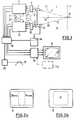
- the device for reproducing three-dimensional images shown in FIG. 1 contains two recording channels, namely a left recording channel L and a right recording channel R.
- the left recording channel L has a camera 1
- the right recording channel R has a camera 2 as image recording elements.
- Both cameras 1 and 2 are attached to a common carrier 3.
- the optical axes of the cameras 1 and 2 are shown in dash-dotted lines and designated 4 and 5.
- the optical axes 4 and 5 intersect at a point 6 of a convergence plane 7, which is shown in broken lines in FIG. 1.
- Both cameras 1, 2 are permanently set to this convergence plane 7. If the surface of an object to be displayed is in the convergence plane 7, the recorded images are successively imaged on a monitor 8 or screen as an image display element at the same location.
- the cameras 1, 2 are conventional vidicons or CCD cameras and are connected on the output side to RGB modules 9, 10, which generate color-coded signals.
- the RGB modules 9, 10 are each followed by processing units 11, 12 with video image memories in the form of RAM memories. It is also possible to use appropriate black and white cameras for three-dimensional display.
- the processing units 11, 12 with the video image memories contain analog / digital converters and RAM memories, not shown, in which the digitized image signals are stored.
- the cameras 1, 2 are synchronized with one another.
- a sensor 13 is attached to the camera 2, which generates signals that are proportional to the distance between the convergence plane 7 and a point, for example 15, on the optical axis 5 on which the camera 2 is currently focused. If the camera 2 is focused on the point 6, the signal at the output of the sensor 13 is zero.
- a corresponding sensor can be attached to the camera 1. Provided that the focus of both cameras 1, 2 is set the same, the sensor 13, which is followed by an evaluation arrangement 14 in which the signal is converted, for example after digitization, into values that are angle-dependent, is sufficient for the exact setting of the images. These are the angles that are taken by the optical axes of the cameras in a first position in which they intersect in the fixed convergence plane and in a second imaginary position in which they intersect in an imaginary convergence plane that is determined by the object. Point 15 corresponds to an imaginary convergence plane 17, in which the imaginary optical axes of the two cameras 1, 2 intersect at point 16. The object to be imaged, which is not shown in more detail, is located in this imaginary convergence plane 17.
- the stored images of the left and right recording channels L and R each come from the video image memories of the processing units 11, 12 into real-time image processing 18, which is controlled by a clock and synchronization circuit, not shown.
- the real-time image processing 18 alternately passes the images of the processing units 11, 12 to a video image memory 19, which is followed by the monitor 8.
- the evaluation arrangement 14 is additionally connected to the real-time image processing 18.
- Apertures 20 for the optical adjustment of at least one pair of glasses 21 are also connected to the real-time image processing 18.
- the device described above is free to choose the image signals with regard to repetition frequency, interlacing and in the choice between full and field methods.
- the deflection of the monitor 8 is influenced by the evaluation unit 14, which generates distance-dependent or angle-dependent signals which cause a corresponding shift of the images of the left and right recording channels on the monitor 8.
- Fig. 2a shows the monitor 8 on which for inclusion in the convergence plane 17, a left image B to the left, which is shown in phantom, is generated, which is shifted to the left side of the monitor 8.
- the right image B on the right recorded by the camera 2, which is shown in broken lines in FIG. 2a, is shifted to the right side of the monitor 8.
- the spatial image B visible through the glasses 21 by the viewer is, as shown in FIG. 2b, in the center of the monitor 8.
- the device described above is very flexible due to the variability of the real-time image processing.
- the images can be shifted against each other.
- the image information can be converted to compensate for the viewing angle. Further image manipulations are possible.
- FIG. 3 shows another embodiment of a device for reproducing three-dimensional images.
- Two cameras 22a, 22b with downstream RGB modules, not shown, are connected to a changeover switch 23, which is operated by a changeover control 24 is operated.
- the switch 23 is followed by a monitor 25 which has a horizontal output stage 26 which is controlled from the outside.
- the output stage 26 is connected to a changeover contact 27, each of which is connected to a potentiometer 28, 29 or a trimmer via two unspecified connections.
- the potentiometers 28, 29 are connected to an operating voltage source, not specified.
- the changeover control 24 actuates both changeover switches 23, 27 simultaneously and the optical diaphragms 30 of glasses 31.
- the potentiometers can be replaced by other offset controls.
- the images of the two synchronized cameras 22a, 22b are passed alternately to the monitor 25 via the changeover switch 23.
- the respective offset reaches the horizontal output stage via changeover switch 27 in synchronism with the changeover of the image switching, so that when image 1 is shown, offset 1 also causes the horizontal shift and vice versa.
- the clock for the switch control 24 can be taken from the image signal at the synchronous signal of the cameras 22a, 22b, at the input signal of the monitor 25 or at another point.
- This system can be used both with and without an interlace method or as a full and field method.
- FIG. 4 shows a device for reproducing three-dimensional images, in which the images are shifted by means of digital buffering.
- two cameras 32, 33 are connected to an arrangement 41 with a video memory 36 via a switch 35 which can be actuated by a changeover control 34.
- Two digital offset controls 38, 39 each for a camera 32, 33 are connected to an address setting device 40 in the arrangement 41 via a changeover switch 37 which can be actuated by the changeover control 34.
- the address setting device 40 is further controlled by a data pointer 42.
- the arrangement 41 is followed by a monitor 43.
- the changeover control 34 also actuates optical diaphragms 44 of glasses 45.
- the offset controls 38, 39 are adjusted manually or by an intelligent control to the focus distance of the cameras 32, 33.
- the images of the two synchronized cameras 32, 33 are passed alternately to the screen memory 36 via the switch 35.
- the respective offset also reaches the screen memory 36 via the changeover switch 37, so that an offset reading or reading out of the image information is made possible by camera.
- the clock for the switchover control can be taken in particular from the synchronous signal of the cameras 32, 33 from the input signal of the monitor or at another point from the image signal.
- This system can also be used both with and without interlacing. If you want to use full-screen methods instead of field, two separate screen memories are necessary.
- Optical systems such as those used in cameras 1 and 2 often have components that do not represent the objects without distortion.
- Distortions can also be caused by the components of the image recording systems or image processing systems shown in FIGS. 1, 3 and 4 connected downstream of the cameras 1, 2.
- Distortions can be caused, for example, by nonlinearities in the optics, oblique angles of incidence, linear and nonlinear geometric transformations within the image acquisition unit. Nonlinearities often occur due to the building blocks of the cameras.
- These distortions can be eliminated by manipulating the image signals supplied by the cameras using correction values. The distortions that occur on the optical path up to the recording part of the respective camera are eliminated as part of real-time image processing.
- the deviations of the images of the objects generated with the image processing system from an exact image of the objects are determined.
- Such an image template can also be generated with a more precise or higher-quality recording and imaging system.
- This image template is compared with the images generated by the cameras.
- an image processing unit (not shown in more detail) is used, which detects the deviations.
- the determined deviations are processed in a correction calculation unit to correct values with which the image signals generated by the cameras are corrected.
- the corrected image is displayed on the monitor or screen. It no longer contains the distortions due to aberrations in the optics and other influences.
- This type of image manipulation makes it possible to reduce the effort involved in producing the optics. It is no longer necessary to reduce aberrations with higher quality optics. When using the cameras for the three-dimensional imaging of objects, this possibility of correction is particularly advantageous.
- the two images, each recorded with a camera Due to tolerances of the components in the recording channels containing the two cameras, it can happen that the two images, each recorded with a camera, have certain differences.
- the differences can be based on linear or non-linear influences that occur, for example, on the optical path or in the adaptation between the optics and the image recording unit.
- Such errors but also errors such as mirror invertedness of the two channels, size differences, rotations of the image coordinates relative to one another and pyramid errors, can be compensated for using the method described below.
- the differences in the images generated by the channels containing the two cameras 1, 2 must be determined.
- the image processing unit already mentioned above is used for this.
- Correction data, with which at least one of the two images is corrected is determined from the deviations with the correction computation unit also mentioned above, i.e.
- the image signals are influenced on the basis of the correction values in such a way that the two images presented to each right and left eye are identical with regard to the compensation of the optical error. This can create an unadulterated three-dimensional impression.
- correction values are normally only determined once.
- the correction data is then available for further processing. If the correction values for the different components of the image recording system or image processing system are determined separately from one another, it is easily possible to assemble or adapt units to an image recording or image processing system.
- the correction values for manipulating the representations can be inserted at various points in the image recording or image processing system. Different possibilities for the correction are shown in FIG. 1.
- the correction can take place directly in the cameras 1, 2 in their readout logic. This is shown in FIG. 1 by the two correction units 46, 48 drawn in dash-dot lines.
- the correction units 46, 48 although drawn outside, are located inside the cameras 1, 2 and Components of the readout logic. With the correction units 46, 48, the image signals are influenced in such a way that distortions and differences between the two recording systems are compensated for.
- correction values are contained in correction value memories 50, 52 in digital form, from which the processing units 11, 12 call up the correction values.
- a correction value processing device 54 which is connected to the video image memory 19 and e.g. In addition to a correction value memory, it contains a processing unit which cooperates with the video image memory 19. In this case, the correction takes place on the imaging part, i.e. the monitor or screen, such as a flat screen, instead. Instead of a monitor or screen, it is also possible to use imaging, glasses-like projectors or projectors on which the images are manipulated by means of the correction values. The correction can be carried out in real-time image processing.
- image recording elements can also be provided.
- an image sensor for example, a single camera with two optics is possible, which contains an image sensor that uses a mechanical or optical diaphragm for the beams of the first or second Optics is released.
- the optics are set to a predeterminable convergence level.
- Another possibility is to generate the two different image information using a camera that has an image sensor with two halves each associated with an optical system. The two halves of the sensor are alternately released for the transmission of signals.
- the optics are focused on a given convergence plane. It is also possible to provide optics that alternately change their beam path and thus have two optical axes in succession that intersect in a convergence plane.
- optical fibers or other optical conductors in connection with image sensors and possibly optical fibers that emit light to the object, in order to monitor objects in difficult to access locations with the aid of three-dimensional representations.
- Areas of application for the devices described above are in particular endoscopes, sensors for robots, sensors for manufacturing processes, e.g. in potentially explosive areas.
- correction data for eliminating errors in the optical or electrical system or in individual components of the system can be obtained by entering a defined signal into the system which is compared with a desired output signal. Correction data can be determined from the deviations.
- An optical template can be used as the input signal, which is compared with the image generated by the system. Correction data can also be obtained by geometrically measuring the generated image and comparing it with the template.
- the above-mentioned real-time image processing 18 is composed in particular of a processor and image memories for the image information obtained from different recording positions, a program memory and an image memory for the recording of the image information shifted to one another.
- the processor performs the desired shifts, rotations, color corrections, reflections, distortions and image transformations.
Landscapes
- Engineering & Computer Science (AREA)
- Multimedia (AREA)
- Signal Processing (AREA)
- Testing, Inspecting, Measuring Of Stereoscopic Televisions And Televisions (AREA)
Applications Claiming Priority (3)
| Application Number | Priority Date | Filing Date | Title |
|---|---|---|---|
| DE4138893 | 1991-11-27 | ||
| DE4138893A DE4138893C1 (enExample) | 1991-11-27 | 1991-11-27 | |
| PCT/EP1992/002732 WO1993011644A1 (de) | 1991-11-27 | 1992-11-26 | Verfahren und vorrichtung zur wiedergabe dreidimensionaler bilder |
Publications (2)
| Publication Number | Publication Date |
|---|---|
| EP0614595A1 EP0614595A1 (de) | 1994-09-14 |
| EP0614595B1 true EP0614595B1 (de) | 1997-03-05 |
Family
ID=6445637
Family Applications (1)
| Application Number | Title | Priority Date | Filing Date |
|---|---|---|---|
| EP92923805A Expired - Lifetime EP0614595B1 (de) | 1991-11-27 | 1992-11-26 | Verfahren und vorrichtung zur wiedergabe dreidimensionaler bilder |
Country Status (4)
| Country | Link |
|---|---|
| EP (1) | EP0614595B1 (enExample) |
| AT (1) | ATE149776T1 (enExample) |
| DE (2) | DE4138893C1 (enExample) |
| WO (1) | WO1993011644A1 (enExample) |
Cited By (1)
| Publication number | Priority date | Publication date | Assignee | Title |
|---|---|---|---|---|
| US8152357B2 (en) | 2005-10-04 | 2012-04-10 | Pfaudler-Werke Gmbh | Mixing tank for liquid substances or the like |
Families Citing this family (2)
| Publication number | Priority date | Publication date | Assignee | Title |
|---|---|---|---|---|
| DE19544811C1 (de) * | 1995-12-01 | 1996-08-01 | Grundig Emv | Verfahren und Anordnung zur dreidimensionalen Videobildauswertung |
| DE19823846C2 (de) * | 1998-05-28 | 2001-04-26 | Sysdrai Datensysteme Und Multi | Vorrichtung und Verfahren zur Erzeugung dreidimensionaler Bilder |
Family Cites Families (4)
| Publication number | Priority date | Publication date | Assignee | Title |
|---|---|---|---|---|
| GB8425827D0 (en) * | 1984-10-12 | 1984-11-21 | Gec Avionics | Position indicating apparatus |
| DE3539440C1 (en) * | 1985-11-07 | 1987-02-05 | Hasso Hofmann | Method and device for generating a pseudo-stereoscopic television picture |
| US4819064A (en) * | 1987-11-25 | 1989-04-04 | The United States Of America As Represented By The Administrator Of The National Aeronautics And Space Administration | Television monitor field shifter and an opto-electronic method for obtaining a stereo image of optimal depth resolution and reduced depth distortion on a single screen |
| DE3808969C1 (en) * | 1988-03-17 | 1989-10-19 | Kernforschungszentrum Karlsruhe Gmbh, 7500 Karlsruhe, De | Device for reproducing three-dimensional pictures |
-
1991
- 1991-11-27 DE DE4138893A patent/DE4138893C1/de not_active Expired - Lifetime
-
1992
- 1992-11-26 DE DE59208143T patent/DE59208143D1/de not_active Expired - Fee Related
- 1992-11-26 EP EP92923805A patent/EP0614595B1/de not_active Expired - Lifetime
- 1992-11-26 AT AT92923805T patent/ATE149776T1/de active
- 1992-11-26 WO PCT/EP1992/002732 patent/WO1993011644A1/de not_active Ceased
Cited By (1)
| Publication number | Priority date | Publication date | Assignee | Title |
|---|---|---|---|---|
| US8152357B2 (en) | 2005-10-04 | 2012-04-10 | Pfaudler-Werke Gmbh | Mixing tank for liquid substances or the like |
Also Published As
| Publication number | Publication date |
|---|---|
| WO1993011644A1 (de) | 1993-06-10 |
| DE4138893C1 (enExample) | 1992-10-22 |
| EP0614595A1 (de) | 1994-09-14 |
| ATE149776T1 (de) | 1997-03-15 |
| DE59208143D1 (de) | 1997-04-10 |
Similar Documents
| Publication | Publication Date | Title |
|---|---|---|
| DE69221346T2 (de) | Vorrichtung und Verfahren zur Erstellung stereoskopischer Bilder | |
| EP0776576B1 (de) | Verfahren und vorrichtung zur darstellung von stereoskopischen videobildern auf einem display | |
| DE19500315C1 (de) | Personenadaptiver autostereoskoper Shutter-Bildschirm (PAAS) | |
| DE69215058T2 (de) | Dreidimensionale Bildwiedergabeeinrichtung, die elektrisch erzeugte Parallaxstreifen verwendet | |
| DE69428611T2 (de) | Autostereoskopische Anzeigevorrichtung | |
| DE69411849T2 (de) | Verfahren zur Verarbeitung von Luminanzpegel in einem zusammengesetzten Bild und Bildverarbeitungssystem zur Anwendung dieses Verfahrens | |
| DE102006055641B4 (de) | Anordnung und Verfahren zur Aufnahme und Wiedergabe von Bildern einer Szene und/oder eines Objektes | |
| EP0342419B1 (de) | Verfahren zur Beobachtung einer Szene und Einrichtung zur Durchführung des Verfahrens | |
| DE69624035T2 (de) | Stereoskopisches Bildanzeigeverfahren und -gerät | |
| EP0836332B1 (de) | Positionsadaptiver, autostereoskoper Monitor (PAM) | |
| DE69601552T2 (de) | Verfahren und vorrichtung zur bildverbesserung | |
| DE3233882C2 (enExample) | ||
| EP0584752B1 (de) | Verfahren zur Erzeugung stereoskopischer Darstellungen | |
| EP0253121A2 (de) | Verfahren und Vorrichtung zur elektronischen Übertragung und/oder Wiedergabe von stereoskopischen Fernsehbildern | |
| DE69009612T2 (de) | Verfahren zur Behandlung und zur Übertragung einer Folge von stereoskopischen Fernsehbilpaaren durch einen Kanal, der einen analogen und einen digitalen Weg enthält. | |
| DE19545356C2 (de) | Vorrichtung zur Darstellung von Stereo-Videobildern | |
| DE68926637T2 (de) | Konvergenzfehler-Korrektur für Festkörperbildaufnahmegeräte | |
| DE2855152A1 (de) | Verfahren und vorrichtung zur wiedergabe eines kinematographischen films mittels eines fernsehempfaengers | |
| EP0945031B1 (de) | Verfahren und schaltungsanordnung zum konvertieren des bildformates von mit zeilenpolarisation hergestellten dreidimensionalen elektronischen bildern | |
| DE19500699A1 (de) | Personen-adaptiver stereoskoper Video-Schirm (PASS) | |
| DE69622055T2 (de) | Vorrichtung zum Anzeigen dreidimensionaler Bilder auf einer Kathodenstrahlröhre | |
| EP0614595B1 (de) | Verfahren und vorrichtung zur wiedergabe dreidimensionaler bilder | |
| DE19542308A1 (de) | Verfahren und Vorrichtung zur Darstellung dreidimensionaler Videobilder | |
| DE3808969C1 (en) | Device for reproducing three-dimensional pictures | |
| DE3421652A1 (de) | Stereoskopisches fernsehsystem |
Legal Events
| Date | Code | Title | Description |
|---|---|---|---|
| PUAI | Public reference made under article 153(3) epc to a published international application that has entered the european phase |
Free format text: ORIGINAL CODE: 0009012 |
|
| 17P | Request for examination filed |
Effective date: 19940624 |
|
| AK | Designated contracting states |
Kind code of ref document: A1 Designated state(s): AT DE FR IT |
|
| GRAG | Despatch of communication of intention to grant |
Free format text: ORIGINAL CODE: EPIDOS AGRA |
|
| 17Q | First examination report despatched |
Effective date: 19960702 |
|
| GRAH | Despatch of communication of intention to grant a patent |
Free format text: ORIGINAL CODE: EPIDOS IGRA |
|
| GRAH | Despatch of communication of intention to grant a patent |
Free format text: ORIGINAL CODE: EPIDOS IGRA |
|
| GRAA | (expected) grant |
Free format text: ORIGINAL CODE: 0009210 |
|
| AK | Designated contracting states |
Kind code of ref document: B1 Designated state(s): AT DE FR IT |
|
| PG25 | Lapsed in a contracting state [announced via postgrant information from national office to epo] |
Ref country code: IT Free format text: LAPSE BECAUSE OF FAILURE TO SUBMIT A TRANSLATION OF THE DESCRIPTION OR TO PAY THE FEE WITHIN THE PRESCRIBED TIME-LIMIT;WARNING: LAPSES OF ITALIAN PATENTS WITH EFFECTIVE DATE BEFORE 2007 MAY HAVE OCCURRED AT ANY TIME BEFORE 2007. THE CORRECT EFFECTIVE DATE MAY BE DIFFERENT FROM THE ONE RECORDED. Effective date: 19970305 Ref country code: FR Effective date: 19970305 |
|
| REF | Corresponds to: |
Ref document number: 149776 Country of ref document: AT Date of ref document: 19970315 Kind code of ref document: T |
|
| REF | Corresponds to: |
Ref document number: 59208143 Country of ref document: DE Date of ref document: 19970410 |
|
| EN | Fr: translation not filed | ||
| PLBE | No opposition filed within time limit |
Free format text: ORIGINAL CODE: 0009261 |
|
| STAA | Information on the status of an ep patent application or granted ep patent |
Free format text: STATUS: NO OPPOSITION FILED WITHIN TIME LIMIT |
|
| 26N | No opposition filed | ||
| PGFP | Annual fee paid to national office [announced via postgrant information from national office to epo] |
Ref country code: AT Payment date: 20001122 Year of fee payment: 9 |
|
| PG25 | Lapsed in a contracting state [announced via postgrant information from national office to epo] |
Ref country code: AT Free format text: LAPSE BECAUSE OF NON-PAYMENT OF DUE FEES Effective date: 20011126 |
|
| PGFP | Annual fee paid to national office [announced via postgrant information from national office to epo] |
Ref country code: DE Payment date: 20020126 Year of fee payment: 10 |
|
| PG25 | Lapsed in a contracting state [announced via postgrant information from national office to epo] |
Ref country code: DE Free format text: LAPSE BECAUSE OF NON-PAYMENT OF DUE FEES Effective date: 20030603 |