EP0614062A2 - Expanded structures - Google Patents
Expanded structures Download PDFInfo
- Publication number
- EP0614062A2 EP0614062A2 EP94301172A EP94301172A EP0614062A2 EP 0614062 A2 EP0614062 A2 EP 0614062A2 EP 94301172 A EP94301172 A EP 94301172A EP 94301172 A EP94301172 A EP 94301172A EP 0614062 A2 EP0614062 A2 EP 0614062A2
- Authority
- EP
- European Patent Office
- Prior art keywords
- expanded
- heat exchanger
- layers
- passage
- sheets
- Prior art date
- Legal status (The legal status is an assumption and is not a legal conclusion. Google has not performed a legal analysis and makes no representation as to the accuracy of the status listed.)
- Withdrawn
Links
Images


Classifications
-
- F—MECHANICAL ENGINEERING; LIGHTING; HEATING; WEAPONS; BLASTING
- F28—HEAT EXCHANGE IN GENERAL
- F28F—DETAILS OF HEAT-EXCHANGE AND HEAT-TRANSFER APPARATUS, OF GENERAL APPLICATION
- F28F3/00—Plate-like or laminated elements; Assemblies of plate-like or laminated elements
- F28F3/12—Elements constructed in the shape of a hollow panel, e.g. with channels
- F28F3/14—Elements constructed in the shape of a hollow panel, e.g. with channels by separating portions of a pair of joined sheets to form channels, e.g. by inflation
-
- B—PERFORMING OPERATIONS; TRANSPORTING
- B21—MECHANICAL METAL-WORKING WITHOUT ESSENTIALLY REMOVING MATERIAL; PUNCHING METAL
- B21D—WORKING OR PROCESSING OF SHEET METAL OR METAL TUBES, RODS OR PROFILES WITHOUT ESSENTIALLY REMOVING MATERIAL; PUNCHING METAL
- B21D53/00—Making other particular articles
- B21D53/02—Making other particular articles heat exchangers or parts thereof, e.g. radiators, condensers fins, headers
- B21D53/04—Making other particular articles heat exchangers or parts thereof, e.g. radiators, condensers fins, headers of sheet metal
- B21D53/045—Making other particular articles heat exchangers or parts thereof, e.g. radiators, condensers fins, headers of sheet metal by inflating partially united plates
-
- B—PERFORMING OPERATIONS; TRANSPORTING
- B23—MACHINE TOOLS; METAL-WORKING NOT OTHERWISE PROVIDED FOR
- B23K—SOLDERING OR UNSOLDERING; WELDING; CLADDING OR PLATING BY SOLDERING OR WELDING; CUTTING BY APPLYING HEAT LOCALLY, e.g. FLAME CUTTING; WORKING BY LASER BEAM
- B23K15/00—Electron-beam welding or cutting
- B23K15/0046—Welding
- B23K15/0053—Seam welding
- B23K15/006—Seam welding of rectilinear seams
-
- B—PERFORMING OPERATIONS; TRANSPORTING
- B23—MACHINE TOOLS; METAL-WORKING NOT OTHERWISE PROVIDED FOR
- B23K—SOLDERING OR UNSOLDERING; WELDING; CLADDING OR PLATING BY SOLDERING OR WELDING; CUTTING BY APPLYING HEAT LOCALLY, e.g. FLAME CUTTING; WORKING BY LASER BEAM
- B23K20/00—Non-electric welding by applying impact or other pressure, with or without the application of heat, e.g. cladding or plating
- B23K20/02—Non-electric welding by applying impact or other pressure, with or without the application of heat, e.g. cladding or plating by means of a press ; Diffusion bonding
-
- B—PERFORMING OPERATIONS; TRANSPORTING
- B23—MACHINE TOOLS; METAL-WORKING NOT OTHERWISE PROVIDED FOR
- B23K—SOLDERING OR UNSOLDERING; WELDING; CLADDING OR PLATING BY SOLDERING OR WELDING; CUTTING BY APPLYING HEAT LOCALLY, e.g. FLAME CUTTING; WORKING BY LASER BEAM
- B23K26/00—Working by laser beam, e.g. welding, cutting or boring
- B23K26/20—Bonding
- B23K26/21—Bonding by welding
- B23K26/24—Seam welding
-
- F—MECHANICAL ENGINEERING; LIGHTING; HEATING; WEAPONS; BLASTING
- F28—HEAT EXCHANGE IN GENERAL
- F28F—DETAILS OF HEAT-EXCHANGE AND HEAT-TRANSFER APPARATUS, OF GENERAL APPLICATION
- F28F9/00—Casings; Header boxes; Auxiliary supports for elements; Auxiliary members within casings
- F28F9/02—Header boxes; End plates
- F28F9/026—Header boxes; End plates with static flow control means, e.g. with means for uniformly distributing heat exchange media into conduits
Definitions
- the present invention relates to expanded structures and more particularly but not exclusively to structures used to form compact heat exchangers suitable for high temperature or corrosive environments.
- Expanded structures have been used extensively in the past in forming aerospace components and heat exchanger cores.
- An expanded structure comprises two or more sheets of material suitably bonded and then deformed in order to form a structural or heat exchanger component.
- the materials are normally diffusion bonded together and may be creep formed, hot formed or superplastically deformed.
- the expanded structure provides added strength and rigidity without great weight gain.
- the expanded structure provides heat exchanger passages through which liquids and/or gases can flow.
- Several expanded structures are stacked to form the heat exchanger. Header or distribution elements are added to ensure separation of flow paths.
- An efficient and compact type of heat exchanger is known to have a plate and fin construction. Such construction has several layers of parallel plates spaced by thin elements in order to define heat exchanger passages. Liquids or gases are distributed along these passages by header arrangements at each end of the heat exchanger.
- brazing introduces dissimilar materials into the heat exchanger. In some applications these dissimilar materials cause corrosion around the braze sites. Attempts have been made to remove brazing from the fabrication procedure by use of diffusion bonding and suitable deformation.
- One means of forming a heat exchanger or expanded structure by diffusion bonding techniques requires at least one plate of each layer to be screen printed with a stop off material in certain areas leaving other areas free in order to define required diffusion bonding at certain locations and areas within the heat exchanger or structure layer surface.
- the plates of the heat exchanger or structure are brought into intimate contact by high pressure and diffusion bonded in the areas where there is no stop off material.
- the diffusion bonded structure or heat exchanger layers may then be superplastically deformed to create heat exchanger passages or expanded areas.
- the heat exchanger or expanded structure is then formed by fabrication of several of these heat exchanger passage layers into a single assembly.
- header means are applied in order to distribute, in use, gases or liquids into and out of the heat exchanger passages. These exchanger passages facilitate mutual heat exchange between respective liquid or gas streams.
- a desired objective in a heat exchanger is to arrange for as many passages per unit width as possible in order to ensure the most efficient heat exchange.
- An inherent problem with stop off material is that there are limitations to how accurately the stop off material can be applied to the layers and secondly there may be a degree of stop off material migration both during assembly of the layers prior to diffusion bonding and during the diffusion bonding process itself. The line bond would be thus impaired.
- the present invention provides an expanded structure suitable for use in a heat exchanger and a method of fabrication of such an expanded structure in which the problems above defined are substantially relieved. Furthermore, the present invention provides the potential for achieving 6 to 12 fins per inch, giving a significant improvement of 50 to 200% on known structures.
- an expanded structure for use in a heat exchanger or component manufacture formed from at least one expanded layer characterised in that each expanded layer has electron beam or laser weld lines in at least two juxtaposed sheets of deformable material and a superplastic, hot formed or creep deformed area between the weld lines to form expanded passages in the layer.
- the expanded structure is adapted for use as a heat exchanger and has header elements coupled to the expanded passages to distribute liquid or gas to and from the expanded passages.
- the weld lines are parallel to one another.
- the expanded layers are grouped together by diffusion bonding.
- the expanded structure is fabricated from the steel SAF 2304.
- the expanded structure is part of a heat exchanger with header means to distribute two liquids or gases in respective heat exchanger passage networks formed from the expanded passage layers.
- the expanded layers are fabricated to have several pairs of sheets of deformable material are welded and fabricated to form in one step structure bundles.
- structure bundles are secured together by diffusion bonding.
- the expanded structure is formed from SAF 2304 steel.
- deformable material 1, 2 are brought into a juxtaposed relationship.
- materials that can be used are titanium alloy 6 Al 4V and stainless steel AVESTA SAF 2304, but non-superplastic materials such as austenitic stainless steels may be used where desired fin shapes can be achieved by creep and conventional hot forming.
- SAF 2304 is a preferred duplex stainless steel because like other steels of similar comparison it has a low propensity to form sigma phase at the deformation and bonding temperature employed.
- the sheets Prior to line welding the sheets are degreased, flashpickled, aligned.
- the sheets to be line welded must be held in close proximity otherwise the weld cannot be sustained.
- the sheet edges are welded 4 together and evacuated to bring them into close proximity before line welding in a picture frame clamping jig.
- the sheets could be clamped and brought into close proximity and line welded then the sheets are edge welded.
- the welds are aligned for example using CNC technology in order to ensure consistency in the later deforming phase.
- CNC computer numerically controlled
- the weld geometry is to a large extent defined by conventional welding parameters.
- electron beam welding can provide more closely pitched welds than laser welding.
- a further feature that must be considered is that a weld crater is created at the end of each weld line. Such craters are eliminated by use of a mechanised slope-out welding technique. This enables greater design flexibility.
- Figure 2 illustrates an expanded passage layer 3 having sheets 1, 2.
- the layer 3 also has an inflation tube 5 and a series of parallel weld lines 7. These weld lines 7 are produced either by laser welding or electron beam welding.
- the fin density is highly dependent upon thickness of the material chosen in association with welding technique. With stop off and diffusion bonding as previously described there is generally a limit of 4 fins per inch with material thicknesses necessary for common pressure performance requirements.
- the use of laser welding or electron beam welding allows densities of 6 - 12 fins per inch with the necessary material thicknesses for pressure performance.
- expanded passage layers 3 can be readily created. However, it would be more commercially viable to provide modules or bundles of several expanded passage layers 3 in one fabrication step. This bundle of layers 3 would be arranged to have passages perpendicular to each other in adjacent layers 3. Furthermore, individual layers 3 can be created and then assembled into bundles or secured together prior to deformation described below.
- Modules or bundles of expanded passage layers 3 can be fabricated by aligning several pairs of sheets of deformable material. These pairs are then welding and deformed as indicated previously. Care must be taken that the weld profile, whether it be electron beam or laser, has a reasonably good consistency between pairs. Thus, typically only three pairs or six sheets of material are weld at the same time. During the deformation phase or at some other period in the fabrication procedure the pairs become diffusion bonded together. Once welded together the layers are simultaneously deformed to create the expanded passages.
- the modules or bundles of expanded passage layers 3 can be considered "building blocks" to create larger expanded structures. Such structures being formed by diffusion bonding modules or bundles together.
- Expanded passage layers 3 can be deformed singularly and then diffusion bonded to secure these single layers together. Alternatively, several or multiple expanded passage layers could be formed in one deformation step. Thus, three sets of expanded passages could be formed at once in three levels of an expanded passage layer. The sets of expanded passages being held together by diffusion bonds between the fins. The diffusion bonding could take place at the same time as the deformation procedure.
- Figure 3 illustrates the layer 3 shown in figure 2 after superplastic or creep deformation. Isostatic argon pressure is presented through inflation tube 5 which causes deformation between weld lines 7 to create expanded passages.
- the actual deformation procedure is highly dependent upon the ratio of weld pitch to sheet thickness.
- preparation for creep and conventional hot deformation or superplastic deformation can be achieved by plastic flexing or cracking the area between weld lines 7 at a temperature of 450-700°C for 1-13 hours and at a pressure up to 600 psi (typically 9 hours at 650°C and 300 psi).
- Actual deformation is conducted at a temperature of, for example, 800 to 950°C in a similar pressure range, (typically 300 psi at 925°C).
- FIG 4 illustrates a section of expanded passage layer 3 in the direction XX ( Figure 3).
- each expanded passage cell 8 has substantially the same cross-sectional area.
- the cells 8 are typically square in shape. However, it is possible to have a high height-to-width ratio and certainly greater than the 1:1 ratio previously achievable.
- the thickness of passage cell 8 wall about the weld line 7 can be greater than that at the top of the cell 8. This is a typical post-form characteristic of the process of superplastic deformation.
- a limitation on cell 8 height is thus prescribed by the necessity of having a sufficient wall thickness to achieve adequate pressure performance at the cell top and corners.
- the cells 8 have a flat top surface due to the effect of a containment tool (not shown).
- the sheets 1, 2 are secured about their edge by side or edge bars 41, 42 (not shown in previous figures). These side or edge bars 41, 42 seal the sheet edges and can be diffusion bonded to the sheets 1, 2.
- the side bars 41, 42 provide a degree of containment as the sheets 1, 2 are deformed and help reduce the distortion effects of the line weld procedure.
- the expanded passage layers 3 are cut after stacking and bonding through an entry zone, that is to say the cell 8 adjacent an edge, in order to expose the passages 8.
- the cut may be lateral or longitudinal with respect to the cell or passage.
- the layers 3 or bundles of layers as indicated previously are stacked and bundled together in an appropriate manner to create at least two flow paths.
- the heat exchanger may comprise a hundred or more layers of expanded (heat exchange) passage layers 3. Once these stacked layers 3 are joined together in an appropriate manner and integrity established by containment of the forming pressure, header means 11 are attached to the entry zone in order to distribute, in operation, liquid or gas through the flow paths of the heat exchanger.
- the header means ensures at least two distinct passage networks through the heat exchanger stack are maintained and that two respective gas or liquid flows do not (unless required) mix.
- the heat exchange stack may be diffusion bonded together or held together by other means such as mechanical straps.
- a heat exchanger in accordance with the present invention could be fabricated from any suitable sheets of superplastic or creep or hot deformable material that can be welded in an appropriate way.
- some titanium alloys, some stainless steels and possibly some plastics materials that can be deformed can be used provided these materials achieve appropriate performance criteria for the eventual heat exchanger. Steels with a low molybdenum content might be useful.
- a heat exchanger in accordance with the present invention will have dimensions of 80 inches by 24 inches by 24 inches.
- Figure 5 illustrates schematically a heat exchanger assembly 51 with header/distribution elements 53 and a heat exchanger area 52. Fluids and/or gases are fed through the header elements 53 to the exchanger area 52. The fluids and/or gases exchange heat energy within the area 52 and may condense or vaporize before exit from the assembly 51 through the elements 53.
- Figure 6 illustrates schematically a passage pattern at entry to the heat exchanger area 52 of the assembly 51 ( Figure 5). It will be appreciated that a fluid or gas flow (arrowhead) is split from the distributor 61 to two channels 62, 63. Thus, the area for heat exchange is increased. It is also possible to provide distribution from one distributor to two, three of four exchanger channels or passages.
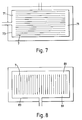
- FIGS 7 to 10 illustrate passage arrangements for heat exchangers including deformed structures in accordance with the present invention.
- Figures 7 and 8 illustrate simple passage arrangements whilst Figures 9 and 10 have diagonal passages.
- Entry zone 71 ( Figure 7) or 81 ( Figure 8) are provided to allow coupling to header elements when the heat exchanger is fabricated.
- the entry zones 71, 81 are formed by leaving a gap between an edge bar 73 ( Figure 7) or 83 ( Figure 8) and the line welds 7.
- edge bar 73, 83 is removed and the flared entry zones 71, 81 exposed.
- Such a flared entry zone 71, 81 allows good input and outlet of liquids or gases to the passages of the layer.
- flared entry zones 71, 81 allow easier coupling to header elements.
- Figure 9 and 10 illustrate passage arrangements having corner entry zones 91 ( Figure 9) and 101 ( Figure 10).
- header means at one end of the stack of expanded layers.
- a relatively high degree of passage expansion and multiple passage distribution can be incorporated into the entry zone 91, 101.
- Such expansion and distribution may facilitate heat exchanger. It will be seen that liquid flowing in accordance with the arrowheads expands in a first part 93, 103 of the passage arrangement. This expanded flow then enters three passages. Thus, the surface area for thermal exchange is greatly increased.
- a heat exchanger stack could be constructed of alternate layers of passage arrangements illustrated in Figures 9 and 10.
Abstract
Description
- The present invention relates to expanded structures and more particularly but not exclusively to structures used to form compact heat exchangers suitable for high temperature or corrosive environments.
- Expanded structures have been used extensively in the past in forming aerospace components and heat exchanger cores. An expanded structure comprises two or more sheets of material suitably bonded and then deformed in order to form a structural or heat exchanger component. The materials are normally diffusion bonded together and may be creep formed, hot formed or superplastically deformed.
- In aerospace components the expanded structure provides added strength and rigidity without great weight gain.
- In heat exchangers, the expanded structure provides heat exchanger passages through which liquids and/or gases can flow. Several expanded structures are stacked to form the heat exchanger. Header or distribution elements are added to ensure separation of flow paths.
- An efficient and compact type of heat exchanger is known to have a plate and fin construction. Such construction has several layers of parallel plates spaced by thin elements in order to define heat exchanger passages. Liquids or gases are distributed along these passages by header arrangements at each end of the heat exchanger.
- There is a requirement for heat exchangers in high temperature and highly corrosive environments. Typically, these exchangers have been manufactured from stainless steel or titanium alloys. At present it is common practice to braze such alloys in order to fabricate the heat exchanger. However, use of brazing can limit the scope of application for the heat exchanger.
- The problem with brazing is that it introduces dissimilar materials into the heat exchanger. In some applications these dissimilar materials cause corrosion around the braze sites. Attempts have been made to remove brazing from the fabrication procedure by use of diffusion bonding and suitable deformation.
- One means of forming a heat exchanger or expanded structure by diffusion bonding techniques requires at least one plate of each layer to be screen printed with a stop off material in certain areas leaving other areas free in order to define required diffusion bonding at certain locations and areas within the heat exchanger or structure layer surface. Thus, the plates of the heat exchanger or structure are brought into intimate contact by high pressure and diffusion bonded in the areas where there is no stop off material. The diffusion bonded structure or heat exchanger layers may then be superplastically deformed to create heat exchanger passages or expanded areas. The heat exchanger or expanded structure is then formed by fabrication of several of these heat exchanger passage layers into a single assembly.
- For a heat exchanger, header means are applied in order to distribute, in use, gases or liquids into and out of the heat exchanger passages. These exchanger passages facilitate mutual heat exchange between respective liquid or gas streams.
- It will be appreciated that a desired objective in a heat exchanger is to arrange for as many passages per unit width as possible in order to ensure the most efficient heat exchange. An inherent problem with stop off material is that there are limitations to how accurately the stop off material can be applied to the layers and secondly there may be a degree of stop off material migration both during assembly of the layers prior to diffusion bonding and during the diffusion bonding process itself. The line bond would be thus impaired. As presently known, there is a limitation on the number of heat exchanger passages that can be fabricated per unit width with a heat exchanger produced by stop off, diffusion bonding and superplastic forming. That limitation is about 4 fins per inch for common material sheet thicknesses.
- An alternative to stop off/diffusion bonding is fusion welding. However, the technique of fusion welding has its own inherent limitations with regard to minimum width and proximity of weld lines, and thus there is a limitation as to how many welds can be formed per unit width.
- An obvious benefit with a heat exchanger having a high number of heat exchanger passages per unit width is that heat exchanger volume needed for given performance criteria is significantly less than an assembly having a lower number of heat exchanger pathways per unit width. Thus, significant energy savings can be made in operation of the exchanger by virtue of increased heat duty or reduced temperature difference in the same volume.
- It is an objective of the present invention to provide an expanded structure suitable for use in a heat exchanger and a method of fabrication of such an expanded structure in which the problems above defined are substantially relieved. Furthermore, the present invention provides the potential for achieving 6 to 12 fins per inch, giving a significant improvement of 50 to 200% on known structures.
- In accordance with a first aspect of the present invention there is provided an expanded structure for use in a heat exchanger or component manufacture formed from at least one expanded layer characterised in that each expanded layer has electron beam or laser weld lines in at least two juxtaposed sheets of deformable material and a superplastic, hot formed or creep deformed area between the weld lines to form expanded passages in the layer.
- Preferably, the expanded structure is adapted for use as a heat exchanger and has header elements coupled to the expanded passages to distribute liquid or gas to and from the expanded passages.
- Preferably, the weld lines are parallel to one another.
- Preferably, the expanded layers are grouped together by diffusion bonding.
- Preferably, the expanded structure is fabricated from the steel SAF 2304.
- Preferably, there are structure plates between expanded layers in the expanded structure.
- In accordance with a second aspect of the present invention there is provided a method of fabricating an expanded structure comprising;
- a. arranging at least two sheets of deformable material in juxtaposed position;
- b. either electron beam or laser welding the sheets to form weld lines therebetween;
- c. fabricating by creep or superplastic deformation or hot forming the sheets between the weld lines to create an expanded passage layer having fins;
- d. stacking several expanded passage layers and securing them together to form an expanded structure.
- Preferably, the expanded structure is part of a heat exchanger with header means to distribute two liquids or gases in respective heat exchanger passage networks formed from the expanded passage layers.
- Preferably, the expanded layers are fabricated to have several pairs of sheets of deformable material are welded and fabricated to form in one step structure bundles.
- Preferably, structure bundles are secured together by diffusion bonding.
- Preferably, the expanded structure is formed from SAF 2304 steel.
- An embodiment of the present invention will now be described by way of example only with reference to the accompanying drawings in which:
- Figure 1 illustrates two sheets of deformable material;
- Figure 2 illustrates the two sheets of deformable material illustrated in Figure 1 welded together in accordance with the present invention;
- Figure 3 illustrates said welded deformable sheets illustrated in Figure 2 when deformed either by superplastic deformation, hot forming or creep to define expanded passages;
- Figure 4 illustrates in schematic form a section of the expanded passage layer illustrated in Figure 3;
- Figure 5 illustrates in schematic block form an expanded configuration incorporating heat exchanger passage layers as illustrated in Figure 3;
- Figure 6 illustrates in schematic plan view a pattern of fins at the entry part of a heat exchanger expanded passage layer which provides means of distributing fluid from one fin opening into two or more fin spacings;
- Figure 7 illustrates in schematic plan view an expanded passage layer having a flared distribution area;
- Figure 8 illustrates in schematic plan view an expanded passage layer arranged to have a flared distribution area which may co-operate with the expanded passage layer illustrated in Figure 7 to provide a heat exchanger structure;
- Figure 9 is a schematic part plan of a distribution pattern for a heat exchanger; and,
- Figure 10 is a schematic part plan of a distribution pattern for a heat exchanger which may co-operate with the distribution pattern illustrated in Figure 9.
- Referring to Figure 1 two sheets of
deformable material - SAF 2304 is a preferred duplex stainless steel because like other steels of similar comparison it has a low propensity to form sigma phase at the deformation and bonding temperature employed. Super duplex steels, such as zeren 100, could be used by employing much higher temperatures to avoid sigma formation.
- Prior to line welding the sheets are degreased, flashpickled, aligned. The sheets to be line welded must be held in close proximity otherwise the weld cannot be sustained. In one method the sheet edges are welded 4 together and evacuated to bring them into close proximity before line welding in a picture frame clamping jig. Alternatively, the sheets could be clamped and brought into close proximity and line welded then the sheets are edge welded. It is essential that the welds are aligned for example using CNC technology in order to ensure consistency in the later deforming phase. By computer numerically controlled (CNC) machinery it is possible also to produce sine wave, segmental wave or any pattern to improve heat transfer. It will be appreciated that the weld geometry is to a large extent defined by conventional welding parameters. Thus, electron beam welding can provide more closely pitched welds than laser welding.
- A further feature that must be considered is that a weld crater is created at the end of each weld line. Such craters are eliminated by use of a mechanised slope-out welding technique. This enables greater design flexibility.
- Figure 2 illustrates an expanded
passage layer 3 havingsheets layer 3 also has aninflation tube 5 and a series of parallel weld lines 7. Theseweld lines 7 are produced either by laser welding or electron beam welding. - It will be appreciated a significant problem with providing
weld lines 7 in the expandedpassage layer 3 is that distortion is created by the welding procedure. Both laser and electron beam welding provide varying degrees of distortion. Solutions to such weld distortion problems may be found in one or a combination of the following:- - 1. Weld the
weld line 7 in an opposing sequence wherebyadjacent weld lines 7 are welded with opposite path directions; - 2. Weld half of the weld lines 7 on one side of the
layer 3 and the other half of the weld lines 7 on the other side, each weld start being from the same position; - 3. Provide weld lines on opposite sides of the
layer 3 as indicated with regard to 2 above but alternate both weld start and direction between each side of thelayer 3; - 4. Provide stress and strain relief in
layer 3 after welding in a jig in a heat treatment furnace or between heated plates; - 5. Provide a jig assembly arranged to localise access to each weld position and thus reduce stress within the
layer 3; - 6. Provide welding of the
layer 3 usingpre-heated sheets - 7. Provide a flattening load in the blowing die during the heat-up phase prior to superplastic or hot forming.
- As indicated above it is an objective of the present invention to provide relatively higher fin densities per unit width than previously achieved. It will be understood that the fin density is highly dependent upon thickness of the material chosen in association with welding technique. With stop off and diffusion bonding as previously described there is generally a limit of 4 fins per inch with material thicknesses necessary for common pressure performance requirements. The use of laser welding or electron beam welding allows densities of 6 - 12 fins per inch with the necessary material thicknesses for pressure performance.
- It will be understood that expanded passage layers 3 can be readily created. However, it would be more commercially viable to provide modules or bundles of several expanded passage layers 3 in one fabrication step. This bundle of
layers 3 would be arranged to have passages perpendicular to each other inadjacent layers 3. Furthermore,individual layers 3 can be created and then assembled into bundles or secured together prior to deformation described below. - Modules or bundles of expanded passage layers 3 can be fabricated by aligning several pairs of sheets of deformable material. These pairs are then welding and deformed as indicated previously. Care must be taken that the weld profile, whether it be electron beam or laser, has a reasonably good consistency between pairs. Thus, typically only three pairs or six sheets of material are weld at the same time. During the deformation phase or at some other period in the fabrication procedure the pairs become diffusion bonded together. Once welded together the layers are simultaneously deformed to create the expanded passages.
- The modules or bundles of expanded passage layers 3 can be considered "building blocks" to create larger expanded structures. Such structures being formed by diffusion bonding modules or bundles together.
- Expanded passage layers 3 can be deformed singularly and then diffusion bonded to secure these single layers together. Alternatively, several or multiple expanded passage layers could be formed in one deformation step. Thus, three sets of expanded passages could be formed at once in three levels of an expanded passage layer. The sets of expanded passages being held together by diffusion bonds between the fins. The diffusion bonding could take place at the same time as the deformation procedure.
- It will be understood that there is a significant advantage with fabrication of expanded structures and, in particular, heat exchangers from single or from relatively small multiple bundles of expanded passage layers, in that these singles or bundles can be individually tested and inspected prior to final expanded structure or heat exchanger construction. Thus, defective singles or bundles can be repaired or eliminated before incorporation in the expanded structure. It is possible that large numbers of expanded passage layers may be held together by welded side bars and gasket interfaces or clamps rather than through diffusion bonding.
- Figure 3 illustrates the
layer 3 shown in figure 2 after superplastic or creep deformation. Isostatic argon pressure is presented throughinflation tube 5 which causes deformation betweenweld lines 7 to create expanded passages. - The actual deformation procedure is highly dependent upon the ratio of weld pitch to sheet thickness. However, it has been found with titanium 6A14V that preparation for creep and conventional hot deformation or superplastic deformation can be achieved by plastic flexing or cracking the area between
weld lines 7 at a temperature of 450-700°C for 1-13 hours and at a pressure up to 600 psi (typically 9 hours at 650°C and 300 psi). It may be beneficial to have a machined groove (or etched groove) in the sheet between the welds to aid initial opening of the passages. Actual deformation is conducted at a temperature of, for example, 800 to 950°C in a similar pressure range, (typically 300 psi at 925°C). - Figure 4 illustrates a section of expanded
passage layer 3 in the direction XX (Figure 3). It will be understood that a primary requirement for expanded passages, especially in heat exchangers is a reasonably high degree of passage cross-section consistency and uniformity. Thus, each expandedpassage cell 8 has substantially the same cross-sectional area. Furthermore, thecells 8 are typically square in shape. However, it is possible to have a high height-to-width ratio and certainly greater than the 1:1 ratio previously achievable. It will also be noted that the thickness ofpassage cell 8 wall about theweld line 7 can be greater than that at the top of thecell 8. This is a typical post-form characteristic of the process of superplastic deformation. A limitation oncell 8 height is thus prescribed by the necessity of having a sufficient wall thickness to achieve adequate pressure performance at the cell top and corners. Thecells 8 have a flat top surface due to the effect of a containment tool (not shown). - It will be seen that the
sheets sheets sheets - As indicated previously, it is desirable to produce bundles or modules of heat exchanger passage layers 3 in order to provide a more economic fabrication procedure. Thus, a combination of three expanded passage layers 3, two with transverse passages and one with longitudinal passages may be brought into association with a thin layer of common titanium alloy between the
layers 3. The assembly is then diffusion bonded together using well-known conditions at a temperature of 925°C and by applying an internal gas pressure of 400 psi to all 3 layers for 2 hours. - Similar results to titanium alloy described above can be achieved with sheets of stainless steel SAF 2304 at a plastic deformation temperature in the range 800-1050°C (typically 980°C and a flex pressure of up to 600 psi, eg 70 psi). Diffusion bonding requirements are also known: typical conditions being 2 hours at a temperature of 980°C and an inflation pressure of 400 psi. However, as previously described the actual deformation temperature and pressure used are dependent on the ratio of weld pitch to sheet thickness.
- In order to fabricate a heat exchanger, the expanded passage layers 3 are cut after stacking and bonding through an entry zone, that is to say the
cell 8 adjacent an edge, in order to expose thepassages 8. The cut may be lateral or longitudinal with respect to the cell or passage. Thelayers 3 or bundles of layers as indicated previously are stacked and bundled together in an appropriate manner to create at least two flow paths. The heat exchanger may comprise a hundred or more layers of expanded (heat exchange) passage layers 3. Once thesestacked layers 3 are joined together in an appropriate manner and integrity established by containment of the forming pressure, header means 11 are attached to the entry zone in order to distribute, in operation, liquid or gas through the flow paths of the heat exchanger. The header means ensures at least two distinct passage networks through the heat exchanger stack are maintained and that two respective gas or liquid flows do not (unless required) mix. The heat exchange stack may be diffusion bonded together or held together by other means such as mechanical straps. - It will be appreciated that a heat exchanger in accordance with the present invention could be fabricated from any suitable sheets of superplastic or creep or hot deformable material that can be welded in an appropriate way. Thus, some titanium alloys, some stainless steels and possibly some plastics materials that can be deformed can be used provided these materials achieve appropriate performance criteria for the eventual heat exchanger. Steels with a low molybdenum content might be useful.
- Typically, a heat exchanger in accordance with the present invention will have dimensions of 80 inches by 24 inches by 24 inches.
- Figure 5 illustrates schematically a
heat exchanger assembly 51 with header/distribution elements 53 and aheat exchanger area 52. Fluids and/or gases are fed through theheader elements 53 to theexchanger area 52. The fluids and/or gases exchange heat energy within thearea 52 and may condense or vaporize before exit from theassembly 51 through theelements 53. - Figure 6 illustrates schematically a passage pattern at entry to the
heat exchanger area 52 of the assembly 51 (Figure 5). It will be appreciated that a fluid or gas flow (arrowhead) is split from thedistributor 61 to twochannels - Figures 7 to 10 illustrate passage arrangements for heat exchangers including deformed structures in accordance with the present invention. Figures 7 and 8 illustrate simple passage arrangements whilst Figures 9 and 10 have diagonal passages. Consider Figures 7 and 8. Entry zone 71 (Figure 7) or 81 (Figure 8) are provided to allow coupling to header elements when the heat exchanger is fabricated. The
entry zones sheets edge bar entry zones entry zone entry zones - It will be appreciated that a heat exchanger stack having the passage arrangements illustrated in Figure 7 and 8 in alternate expanded passage layers could be fabricated.
- Figure 9 and 10 illustrate passage arrangements having corner entry zones 91 (Figure 9) and 101 (Figure 10). Thus, it is possible to locate header means at one end of the stack of expanded layers. Furthermore, a relatively high degree of passage expansion and multiple passage distribution can be incorporated into the
entry zone first part - It will be appreciated that a heat exchanger stack could be constructed of alternate layers of passage arrangements illustrated in Figures 9 and 10.
Claims (9)
- (1) An expanded structure for use in a heat exchanger or component manufacture formed from at least one expanded layer characterised in that each expanded layer has electron beam or laser weld lines in at least two juxtaposed sheets of deformable material and a superplastic, hot formed or creep deformed area between the weld lines to form expanded passages in the layer.
- (2) An expanded structure as claimed in claim 1 wherein the structure has header elements coupled to the expanded passages to distribute liquid or gas to and from the expanded passages and allow the structure to operate as a heat exchanger.
- (3) An expanded structure as claimed in claim 1 or 2 wherein the weld lines are parallel to one another.
- (4) An expanded structure as claimed in claim 1, 2 or 3 wherein the expanded layers are grouped together by diffusion bonding.
- (5) An expanded structure as claimed in any proceeding claim wherein there are structure plates between expanded layers in the expanded structure.
- (6) A method of fabricating an expanded structure comprising;a. arranging at least two sheets of deformable material in juxtaposed position;b. either electron beam or laser welding the sheets to form weld lines therebetween;c. fabricating by creep or superplastic deformation or hot forming the sheets between the weld lines to create an expanded passage layer having fins;d. stacking several expanded passage layers and securing them together to form an expanded structure.
- (7) A method as claimed in claim 6 wherein once the expanded passage layers are secured together then header means are added to the expanded structure in order to allow the structure to act as a heat exchanger by distribution of liquids or gases in respective heat exchanger passage networks formed from the expanded passage layers.
- (8) A method as claimed in claim 6 or 7 wherein several pairs of sheets of deformable material are welded and fabricated together in one step to form structure bundles which are then secured together to produce the expanded structure.
- (9) A method as claimed in claim 6, 7 or 8 wherein the expanded passage layers are secured together by diffusion bonding.
Applications Claiming Priority (2)
| Application Number | Priority Date | Filing Date | Title |
|---|---|---|---|
| GB9304449 | 1993-03-04 | ||
| GB939304449A GB9304449D0 (en) | 1993-03-04 | 1993-03-04 | Expanded structures |
Publications (2)
| Publication Number | Publication Date |
|---|---|
| EP0614062A2 true EP0614062A2 (en) | 1994-09-07 |
| EP0614062A3 EP0614062A3 (en) | 1995-03-22 |
Family
ID=10731480
Family Applications (1)
| Application Number | Title | Priority Date | Filing Date |
|---|---|---|---|
| EP94301172A Withdrawn EP0614062A3 (en) | 1993-03-04 | 1994-02-18 | Expanded structures. |
Country Status (4)
| Country | Link |
|---|---|
| EP (1) | EP0614062A3 (en) |
| JP (1) | JPH0755381A (en) |
| GB (1) | GB9304449D0 (en) |
| NO (1) | NO940740L (en) |
Cited By (6)
| Publication number | Priority date | Publication date | Assignee | Title |
|---|---|---|---|---|
| EP0753363A1 (en) * | 1994-04-26 | 1997-01-15 | Erhardt Bischoff GmbH & Co KG | Method of producing hollow bodies |
| NL1004321C2 (en) * | 1996-10-21 | 1998-04-22 | Omega Laser Systems B V | Method for production of rigidly shaped hollow panel through which pressurised medium flows |
| EP0928941A2 (en) * | 1998-01-07 | 1999-07-14 | N.V. Vasco | Flat radiator |
| NL1009138C2 (en) * | 1998-05-12 | 1999-11-15 | Omega Engineering B V | Method for manufacturing a non-flat tank wall or part thereof, and a tank wall or tank wall part. |
| WO2014086405A1 (en) * | 2012-12-05 | 2014-06-12 | Stetter Gmbh | Evaporator plate for ice production |
| EP3831505A1 (en) * | 2019-12-05 | 2021-06-09 | Airbus Operations | Method for manufacturing a heat exchanger from titanium |
Families Citing this family (1)
| Publication number | Priority date | Publication date | Assignee | Title |
|---|---|---|---|---|
| CN109604436B (en) * | 2018-11-29 | 2020-11-03 | 湖北三江航天江北机械工程有限公司 | Method for forming variable-section special-shaped single tube of thrust chamber body part of liquid rocket engine |
Citations (3)
| Publication number | Priority date | Publication date | Assignee | Title |
|---|---|---|---|---|
| JPS58128236A (en) * | 1982-01-26 | 1983-07-30 | Riken Corp | Manufacture of heat collector |
| EP0213217A1 (en) * | 1983-11-21 | 1987-03-11 | Rockwell International Corporation | Laser welding of sandwich structures |
| EP0460872A1 (en) * | 1990-06-06 | 1991-12-11 | ROLLS-ROYCE plc | Heat exchangers |
-
1993
- 1993-03-04 GB GB939304449A patent/GB9304449D0/en active Pending
-
1994
- 1994-02-18 EP EP94301172A patent/EP0614062A3/en not_active Withdrawn
- 1994-03-03 NO NO940740A patent/NO940740L/en unknown
- 1994-03-04 JP JP3499594A patent/JPH0755381A/en active Pending
Patent Citations (3)
| Publication number | Priority date | Publication date | Assignee | Title |
|---|---|---|---|---|
| JPS58128236A (en) * | 1982-01-26 | 1983-07-30 | Riken Corp | Manufacture of heat collector |
| EP0213217A1 (en) * | 1983-11-21 | 1987-03-11 | Rockwell International Corporation | Laser welding of sandwich structures |
| EP0460872A1 (en) * | 1990-06-06 | 1991-12-11 | ROLLS-ROYCE plc | Heat exchangers |
Non-Patent Citations (1)
| Title |
|---|
| PATENT ABSTRACTS OF JAPAN vol. 7, no. 240 (M-251) 25 October 1983 & JP-A-58 128 236 (SUZUKY KAZUMA) 30 July 1983 * |
Cited By (10)
| Publication number | Priority date | Publication date | Assignee | Title |
|---|---|---|---|---|
| EP0753363A1 (en) * | 1994-04-26 | 1997-01-15 | Erhardt Bischoff GmbH & Co KG | Method of producing hollow bodies |
| NL1004321C2 (en) * | 1996-10-21 | 1998-04-22 | Omega Laser Systems B V | Method for production of rigidly shaped hollow panel through which pressurised medium flows |
| EP0928941A2 (en) * | 1998-01-07 | 1999-07-14 | N.V. Vasco | Flat radiator |
| EP0928941A3 (en) * | 1998-01-07 | 1999-12-29 | N.V. Vasco | Flat radiator |
| NL1009138C2 (en) * | 1998-05-12 | 1999-11-15 | Omega Engineering B V | Method for manufacturing a non-flat tank wall or part thereof, and a tank wall or tank wall part. |
| WO1999058920A1 (en) * | 1998-05-12 | 1999-11-18 | Omega Engineering Holding B.V. | Method of manufacturing a curved container wall |
| WO2014086405A1 (en) * | 2012-12-05 | 2014-06-12 | Stetter Gmbh | Evaporator plate for ice production |
| EP3831505A1 (en) * | 2019-12-05 | 2021-06-09 | Airbus Operations | Method for manufacturing a heat exchanger from titanium |
| FR3104048A1 (en) * | 2019-12-05 | 2021-06-11 | Airbus | MANUFACTURING PROCESS OF A TITANIUM HEAT EXCHANGER |
| US11958147B2 (en) | 2019-12-05 | 2024-04-16 | Airbus Sas | Manufacturing method for a titanium heat exchanger |
Also Published As
| Publication number | Publication date |
|---|---|
| NO940740L (en) | 1994-09-05 |
| GB9304449D0 (en) | 1993-04-21 |
| JPH0755381A (en) | 1995-03-03 |
| EP0614062A3 (en) | 1995-03-22 |
| NO940740D0 (en) | 1994-03-03 |
Similar Documents
| Publication | Publication Date | Title |
|---|---|---|
| US5983992A (en) | Unit construction plate-fin heat exchanger | |
| US6305079B1 (en) | Methods of making plate-fin heat exchangers | |
| AU638132B2 (en) | Heat exchangers | |
| US5465785A (en) | Heat exchanger | |
| US8177932B2 (en) | Method for manufacturing a micro tube heat exchanger | |
| EP0577616B1 (en) | Heat exchanger | |
| US5287918A (en) | Heat exchangers | |
| US4217397A (en) | Metallic sandwich structure and method of fabrication | |
| US4308915A (en) | Thin sheet heat exchanger | |
| US5723225A (en) | Superplastically formed, diffusion bonded multiple sheet panels with web doublers and method of manufacture | |
| US20100263846A1 (en) | Plate Heat Exchanger Having Profiles | |
| CN107167000A (en) | The method of heat-exchangers of the plate type and manufacture heat-exchangers of the plate type | |
| US5289965A (en) | Method of superplastically forming and braze bonding a structure | |
| EP0614062A2 (en) | Expanded structures | |
| US4373243A (en) | Method of forming reinforced plate-type heat exchanger | |
| US20010025705A1 (en) | Offset counterflow matrix fin for a counterflow plate-fin heat exchanger with crossflow headers | |
| DE3710823C2 (en) | ||
| JP3025441B2 (en) | Method for manufacturing first cooling wall of fusion reactor | |
| US5850722A (en) | Lightweight superplastically formed, diffusion bonded panel structure and process of manufacture | |
| JPH04347496A (en) | Plate type heat exchanger | |
| WO1999011993A1 (en) | Heat exchanger | |
| JP2003205335A (en) | Heat exchanger element, and method for manufacturing heat exchanger | |
| JPH10128473A (en) | Honeycomb panel provided with end core and its production | |
| JPS63188036A (en) | Honeycomb core made of special alloy | |
| AU7643681A (en) | Thin sheet heat exchanger |
Legal Events
| Date | Code | Title | Description |
|---|---|---|---|
| PUAI | Public reference made under article 153(3) epc to a published international application that has entered the european phase |
Free format text: ORIGINAL CODE: 0009012 |
|
| AK | Designated contracting states |
Kind code of ref document: A2 Designated state(s): DE FR GB IT NL SE |
|
| PUAL | Search report despatched |
Free format text: ORIGINAL CODE: 0009013 |
|
| AK | Designated contracting states |
Kind code of ref document: A3 Designated state(s): DE FR GB IT NL SE |
|
| 17P | Request for examination filed |
Effective date: 19950804 |
|
| 17Q | First examination report despatched |
Effective date: 19960506 |
|
| RAP3 | Party data changed (applicant data changed or rights of an application transferred) |
Owner name: DONCASTERS PLC Owner name: IMI MARSTON LIMITED |
|
| STAA | Information on the status of an ep patent application or granted ep patent |
Free format text: STATUS: THE APPLICATION IS DEEMED TO BE WITHDRAWN |
|
| 18D | Application deemed to be withdrawn |
Effective date: 19980226 |