EP0613708B1 - Device for cleaning a basin - Google Patents
Device for cleaning a basin Download PDFInfo
- Publication number
- EP0613708B1 EP0613708B1 EP94101866A EP94101866A EP0613708B1 EP 0613708 B1 EP0613708 B1 EP 0613708B1 EP 94101866 A EP94101866 A EP 94101866A EP 94101866 A EP94101866 A EP 94101866A EP 0613708 B1 EP0613708 B1 EP 0613708B1
- Authority
- EP
- European Patent Office
- Prior art keywords
- cleaning device
- cleaning
- substances
- basin
- separated
- Prior art date
- Legal status (The legal status is an assumption and is not a legal conclusion. Google has not performed a legal analysis and makes no representation as to the accuracy of the status listed.)
- Expired - Lifetime
Links
Images


Classifications
-
- B—PERFORMING OPERATIONS; TRANSPORTING
- B01—PHYSICAL OR CHEMICAL PROCESSES OR APPARATUS IN GENERAL
- B01D—SEPARATION
- B01D21/00—Separation of suspended solid particles from liquids by sedimentation
- B01D21/18—Construction of the scrapers or the driving mechanisms for settling tanks
Definitions
- the invention relates to a device for cleaning a basin, in particular for removing mud or sand, which has a cleaning unit for receiving the substances to be separated and passed on to a transfer point for disposal, as well as a travel unit with a drive control device and a drive for generating a Travel movement of the cleaning unit is provided.
- a large area of application for such devices is settling or clarifying tanks of sewage treatment plants.
- basins there is a separation between substances to be separated and a liquid.
- more or less large ones fall Amounts of mud or sand on the bottom of the pool.
- the pelvic floor is cleaned of the accumulated substances when the pelvis is full.
- the cleaning is carried out by means of a rotatable clearing blade which is moved over the bottom of the basin and the pushed-together sludge reaches a central sludge discharge box via suction lines.
- Such clearing blades are permanently installed with their drive unit in the basin and their dimensions are adapted to the shape and size of the basin.
- the cleaning process is either carried out in continuous operation or repeated at predetermined time intervals or arbitrarily.
- a major disadvantage is that the cleaning device can only be used for one pool due to the fixed installation and adaptation.
- Another disadvantage is the inadequate possibility of adapting the cleaning process to the actual conditions, in particular with regard to the amount of the substances to be separated. It is therefore often the case that the often extremely heavy cleaning devices are moved at a high cost because of a few kilograms of sludge.
- insufficient cleaning results result from cleaning intervals which are too large for the amount of the substances to be separated, and which can then no longer be handled by the cleaning device.
- a good effectiveness of the sludge clearing is to be achieved by adapting the clearing speed to the concentration of the sludge.
- the guide element of a linear motor is attached to the bottom part of a settling basin, with a movable clearing device being designed as a movable element of the linear motor.
- the concentration of the sludge is monitored with a measuring device arranged on the water surface, the signals of which determine the clearing process and the clearing speed of the sludge scraper that can be moved on the ground.
- the measuring device for determining the sludge concentration and thus for resolving the clearing process only records the layer thickness or concentration of the sludge layer in a defined area and can therefore not react sufficiently flexibly to different sludge accumulations distributed over the floor area of the sedimentation basin.
- the invention is therefore based on the object of providing a device for cleaning a basin which also works under water and which achieves an economical course of the cleaning process and good cleaning results under changing operating conditions, such as, for example, a fluctuating amount of the substances to be separated or for different basin shapes.
- the object of the invention is that at least one first sensor for detecting the quantity and / or location of the substances to be removed is provided on the movable cleaning device, and that a computer unit has the output signals of the first sensor as a reference variable for generating Computer processed output signals for the driving control device for flexible travel movement adapted to the location or the location and the amount of the accumulated substances, whereby the cleaning device can be moved in different directions with the aid of its travel unit as a self-propelled structural unit, depending on the location of the accumulation of substances to be deposited.
- An optical sensor for example an infrared sensor, advantageously in a multiple arrangement, can expediently be used as the first sensor.
- other sensors can also be used.
- the cleaning device according to the invention is capable of automatically recognizing the resulting task and initiating the cleaning process. So it can a very extensive automation of the cleaning process can be achieved with improved cleaning results at the same time.
- the cleaning device is expediently movable under the floor.
- a constructive solution can provide guidelines in the form of matrices, aligned vertically and horizontally to one another, along which the cleaning device can be moved. These guidelines can preferably be parts of an electronic control device for electronic route control.
- the cleaning unit has at least one sludge clearing tool.
- the sludge clearing tool is usually a clearing blade with which the sludge is pushed to a transfer point in a conveyor.
- the computer unit has artificial intelligence, as a result of which it can output different control signals for optimizing the cleaning process to the driving control device in the same initial situations.
- This is a "learnable" computer unit, which is provided, for example, with an expert system which, according to heuristic methods, strives to develop an optimal cleaning strategy for every application. Previous cleaning processes serve as experience and are used together with corresponding rules to develop the respective cleaning strategy. It is therefore possible to also to react to peculiarities and loads in which a normal control program of such devices is overwhelmed.
- the cleaning device 1 shown in FIGS. 1 to 3 has a cleaning unit 2 and a displacement unit 3, which together form a compact structural unit that can be moved on a floor part, preferably a pool floor.
- the travel unit 3 contains a travel drive 5 for generating the travel movement by travel elements designed as running wheels 6 or caterpillar tracks, and also a travel control device 7.
- the cleaning device 1 is provided with a first type of sensor 8 (first sensor) in order to identify the quantity and the location of the substances to be removed.
- This first sensor is expediently designed as an optical sensor, for example as an infrared sensor.
- a second type of sensor 9 (second sensor) is used to determine the consistency of the substances to be removed.
- This second sensor can, for example, advantageously be designed as an acoustic sensor, in particular as a sound reflex sensor based on the sounder principle. In principle, however, other sensors are also possible and, if appropriate, expedient.
- Both sensors are connected to the input of a computer unit 10.
- the output of the computer unit 10 controls the traction drive 5 with the interposition of a signal amplifier (not shown in the drawing) via the traction control device 7.
- a learning-capable expert system is present in a memory of the computing unit 10.
- the cleaning unit 2 has a mud clearing plate 16 which is located on the front 17 of the cleaning device 1. At the rear of the cleaning device 1, a further sludge clearing tool 16a is provided, so that the cleaning device 1 can clear in two directions of travel.
- the receiving recess of the sludge clearing plate 16 is connected by a hose 18 to the sludge suction device 15, and this conveys the extracted sludge from the sludge clearing plate 16 or clearing tool 16a to a connection adapter 19 of the cleaning device 1, to which a further hose or other connecting element for continuing the sludge can be connected to a transfer point for disposal.
- the cleaning device 1 can advantageously be provided with a sludge intermediate store, which can advantageously also be designed such that the sludge is only discharged at a specific transfer point in the path of the cleaning device, preferably at the end of the path.
- the water-sensitive parts of the cleaning device 1 are enclosed in a watertight housing 20, so that the cleaning device 1 is fully submersible without any risk to these parts.
- the cleaning device 1 is located on the bottom of the basin 22 in a settling basin filled with water, in the form of a longitudinal basin 21.
- the connection adapter 19 of the cleaning unit 2 is connected to a central transfer point 24 by a flexible hose 23 for the further transport of sludge.
- sludge has accumulated on the bottom of the basin 22 of the longitudinal basin 21, which makes cleaning of the bottom of the basin 22 necessary in terms of quantity, consistency, local accumulation or other parameters, this is automatically recognized by the sensors 8, 9 and the cleaning process is initiated.
- the corresponding Output signals from the sensors 8, 9 reach the computer unit 10 as reference variables, where they are used by the expert system to generate computer output signals.
- the computer output signals forwarded to the travel control device 7 for controlling the travel drive 5 are generated primarily from the point of view of the most economical travel movement of the cleaning device 1. This essentially means that the travel distances and the duration of use should be as short as possible.
- the movement of the cleaning device 1 can take any direction on the pelvic floor 22 and the speed of the movement can be adapted to the local accumulation of the sludge.
- Another possibility, not shown in this embodiment, of reacting to different amounts of sludge to be extracted consists in an advantageous adaptation of the performance of the extraction device, which can also be controlled by the computer unit 10 by means of corresponding signals. If necessary, both options can be combined in a constructive solution to deal with the locally different amounts of sludge to be separated.
- the dimensions of the compact self-propelled cleaning device 1 are by far smaller than those of the settling basin 21. Since the dimensions of the cleaning device 1 do not require adaptation to the basin dimensions, there is the essential advantage that the cleaning device 1 can be used successively in several different pools. For example, it is easily possible to also use the cleaning device 1 for one Round pools or to use for other pool shapes. For example, a mobile crane can be used to remove and insert the cleaning device 1 into different basins. In practice, it has been shown that there are a large number of applications in which the cleaning intervals for the individual basins are large enough to use a single cleaning device in succession in several basins. This is of great economic importance for the operators of such systems, since they no longer have to procure and install their own cleaning device for each pool.
- the cleaning device according to the embodiment shown in FIG. 1 is also used.
- a telescopically adjustable length 31 is connected on one side to the connection adapter 19 with the associated adjustment drive.
- the length of the adjustable tube 31 is to be set up in such a way that the outlet side of the tube 31 is located in a trough 33 in a basin independently of the movement of the cleaning device 1 via a transfer point running parallel to the longitudinal edge 32 of the longitudinal basin 30.
- an adjustment drive of the transfer tube can be dispensed with if the outlet side of the tube 31 has a mechanical positive guide, which ensures that the tube mouth always lies above the channel 33.
- the cleaning device 1 can be moved along a pipe bridge 37 transversely to the longitudinal direction of the pool.
- the longitudinal movement is transmitted to the cleaning device 1 by the tube bridge 37 which can be moved in the longitudinal direction of the pool.
- the pipe bridge 37 can be moved parallel to the upper longitudinal edges 40 of the longitudinal pool 39 on rail guides, not shown in the drawing.
- the connection adapter 19 of the cleaning device 1 is connected to the pipe bridge 37 via a connecting hose 36.
- the substances to be separated are discharged via the hose 36 into the free interior of the pipe 38 or a corresponding channel on the pipe bridge 37. From there they arrive, analogous to the design according to FIG. 5, into a channel 41 running parallel along the upper longitudinal edge 40.
- the use of two channels 41 is also possible, which are each arranged parallel on both sides to the upper longitudinal edges 40 of the longitudinal pool 39 .
- the control of the movement of the pipe bridge 37 can also be carried out by the computer unit 10. Since the pipe bridge 37 is expediently used in addition to generating the longitudinal movement of the cleaning device 1, the moving unit 3 of the cleaning device 1 only has to produce corresponding transverse movements to the longitudinal direction of the basin 39.
- the cleaning device according to the invention according to FIG. 6 thus differs in its connection to the delivery point from the previously described embodiments. All other features of the structural unit shown in FIGS. 1 to 3, in particular with regard to the sensors and the computer unit and the possibilities resulting therefrom, are also realized in this embodiment according to the invention.
- a plurality of cleaning devices 1 can also be used in one basin.
Abstract
Description
Die Erfindung betrifft eine Vorrichtung zur Reinigung eines Beckens, insbesondere zur Entfernung von Schlamm oder Sand, welche eine Reinigungseinheit zur Aufnahme der abzuscheidenden Stoffe und zur Weiterführung an eine Übergabestelle zur Entsorgung aufweist sowie mit einer Verfahreinheit, die mit einer Fahrsteuereinrichtung und einem Fahrantrieb zur Erzeugung einer Verfahrbewegung der Reinigungseinheit versehen ist.The invention relates to a device for cleaning a basin, in particular for removing mud or sand, which has a cleaning unit for receiving the substances to be separated and passed on to a transfer point for disposal, as well as a travel unit with a drive control device and a drive for generating a Travel movement of the cleaning unit is provided.
Ein großes Anwendungsgebiet für derartige Vorrichtungen sind Absetz- oder Klärbecken von Kläranlagen. In solchen Becken findet eine Trennung zwischen abzuscheidenden Stoffen und einer Flüssigkeit statt. Dabei fallen in Abhängigkeit von der Menge der in der Flüssigkeit vorhandenen abzuscheidenden Stoffe mehr oder weniger große Mengen an Schlamm bzw. Sand auf der Beckensohle an. Mit Hilfe von geeigneten Werkzeugen wird die Beckensohle, im gefüllten Zustand des Beckens, von den angefallenen Stoffen gereinigt.A large area of application for such devices is settling or clarifying tanks of sewage treatment plants. In such basins, there is a separation between substances to be separated and a liquid. Depending on the amount of the substances to be separated out in the liquid, more or less large ones fall Amounts of mud or sand on the bottom of the pool. With the help of suitable tools, the pelvic floor is cleaned of the accumulated substances when the pelvis is full.
Bei einer vorbekannten Reinigungsvorrichtung nach DE-A-37 15 021 zur Benutzung im gefüllten Becken wird die Reinigung durch ein drehbares Räumschild vorgenommen, welches über die Beckensohle bewegt wird und wobei der zusammengeschobene Schlamm über Absaugleitungen in einen zentralen Schlammabzugskasten gelangt. Derartige Räumschilde sind mit ihrer Antriebseinheit fest in das Becken installiert und in ihren Abmessungen an Form und Größe des Beckens angepaßt. Der Reinigungsvorgang wird dabei entweder im Dauerbetrieb vorgenommen oder aber in vorgegebenen Zeitintervallen bzw. willkürlich wiederholt.In a previously known cleaning device according to DE-A-37 15 021 for use in the filled basin, the cleaning is carried out by means of a rotatable clearing blade which is moved over the bottom of the basin and the pushed-together sludge reaches a central sludge discharge box via suction lines. Such clearing blades are permanently installed with their drive unit in the basin and their dimensions are adapted to the shape and size of the basin. The cleaning process is either carried out in continuous operation or repeated at predetermined time intervals or arbitrarily.
Daraus ergeben sich Nachteile vorbekannter Reinigungsvorrichtungen. Ein wesentlicher Nachteil besteht darin, daß die Reinigungsvorrichtung aufgrund der festen Installation und der Anpassung stets nur für ein Becken verwendet werden kann. Ebenfalls nachteilig ist die unzureichende Möglichkeit, den Reinigungsvorgang an die tatsächlich vorhandenen Verhältnisse, insbesondere bezüglich der Menge der angefallenen abzuscheidenden Stoffe anzupassen. Es ist somit häufig der Fall, daß die oftmals äußerst schweren Reinigungsvorrichtungen unter hohem Kostenaufwand wegen weniger Kilogramm Schlamm bewegt werden. Im umgekehrten Fall resultieren unzureichende Reinigungsergebnisse aus für die Menge der abzuscheidenden Stoffe zu großen Reinigungsintervallen, die dann durch die Reinigungsvorrichtung nicht mehr bewältigt werden können.This results in disadvantages of previously known cleaning devices. A major disadvantage is that the cleaning device can only be used for one pool due to the fixed installation and adaptation. Another disadvantage is the inadequate possibility of adapting the cleaning process to the actual conditions, in particular with regard to the amount of the substances to be separated. It is therefore often the case that the often extremely heavy cleaning devices are moved at a high cost because of a few kilograms of sludge. In the opposite case, insufficient cleaning results result from cleaning intervals which are too large for the amount of the substances to be separated, and which can then no longer be handled by the cleaning device.
Bei der aus der JP-A-62 061 604 vorbekannten Reinigungsvorrichtung soll eine gute Wirksamkeit der Schlammräumung dadurch erzielt werden, daß die Räumgeschwindigkeit der Konzentration des Schlammes angepaßt wird. Hierzu ist das Führungselement eines Linearmotors am Bodenteil eines Absetzbeckens angebracht, wobei ein verfahrbares Räumgerät als bewegliches Element des Linearmotors ausgebildet ist. Die Konzentration des Schlamms wird mit einem an der Wasseroberfläche angeordneten Meßgerät überwacht, dessen Signale den Räumvorgang und die Räumgeschwindigkeit des bodenverfahrbaren Schlammräumers bestimmen.In the cleaning device known from JP-A-62 061 604, a good effectiveness of the sludge clearing is to be achieved by adapting the clearing speed to the concentration of the sludge. For this purpose, the guide element of a linear motor is attached to the bottom part of a settling basin, with a movable clearing device being designed as a movable element of the linear motor. The concentration of the sludge is monitored with a measuring device arranged on the water surface, the signals of which determine the clearing process and the clearing speed of the sludge scraper that can be moved on the ground.
Es handelt sich hier nur um eine reine Linearbewegung des Räumgerätes 6, welches nur in einer Richtung, nämlich bei Vorwärtsfahrt des zwischen zwei Endlagen des von Sonarsensoren gesteuerten Räum - gerätes 6, räumt.This is only a pure linear movement of the
Das Meßgerät zur Feststellung der Schlammkonzentration und damit zur Auflösung des Räumvorganges erfaßt die Schichtdicke bzw. Konzentration der Schlammschicht nur in einem definierten Bereich und kann somit auf unterschiedlichen Schlammanfall verteilt über die Bodenfläche des Absetzbeckens nicht hinreichend flexibel reagieren.The measuring device for determining the sludge concentration and thus for resolving the clearing process only records the layer thickness or concentration of the sludge layer in a defined area and can therefore not react sufficiently flexibly to different sludge accumulations distributed over the floor area of the sedimentation basin.
Der Erfindung liegt daher die Aufgabe zugrunde, eine auch unter Wasser arbeitende Vorrichtung zur Reinigung eines Beckens zur Verfügung zu stellen, die unter wechselnden Einsatzbedingungen, wie beispielsweise schwankender Menge der abzuscheidenden Stoffe oder für unterschiedliche Beckenformen, einen ökonomischen Verlauf des Reinigungsvorganges und gute Reinigungsergebnisse erzielt.The invention is therefore based on the object of providing a device for cleaning a basin which also works under water and which achieves an economical course of the cleaning process and good cleaning results under changing operating conditions, such as, for example, a fluctuating amount of the substances to be separated or for different basin shapes.
Die erfindungsgemäße Lösung der Aufgabe besteht darin, daß an der verfahrbaren Reinigungsvorrichtung mindestens ein erster Sensor zur Erkennung der Menge und/oder des Ortes der angefallenen zu entfernenden Stoffe vorgesehen ist, und daß eine Rechnereinheit vorhanden ist die Ausgangssignale des ersten Sensors als Führungsgröße zur Erzeugung von Rechnerausgangssignalen für die Fahrsteuereinrichtung zur flexiblen dem Ort oder dem Ort und der Menge der angefallenen Stoffe angepaßten Verfahrbewegung weiterverarbeitet, wodurch die Reinigungsvorrichtung mit Hilfe ihrer Verfahreinheit als selbstverfahrbare Baueinheit, je nach dem Ort der Anhäufung abzuscheidender Stoffe, in unterschiedliche Richtungen verfahrbar ist. Durch eine derartige Ausbildung einer Reinigungsvorrichtung ist gewährleistet, daß sich durch äußere Bedingungen ergebende variierende Reinigungsaufgaben durch eine einzige Reinigungsvorrichtung, unter Vermeidung der Nachteile der durch den Stand der Technik vorbekannten Reinigungsvorrichtungen, gelöst werden können. Als erster Sensor kann zweckmäßig ein optischer Sensor, beispielsweise ein Infrarotsensor, vorteilhaft in Mehrfachanordnung,verwendet werden. Je nach den gegebenen Verhältnissen und der Art der zu entfernenden Stoffe können jedoch auch andere Sensoren benutzt werden.The object of the invention is that at least one first sensor for detecting the quantity and / or location of the substances to be removed is provided on the movable cleaning device, and that a computer unit has the output signals of the first sensor as a reference variable for generating Computer processed output signals for the driving control device for flexible travel movement adapted to the location or the location and the amount of the accumulated substances, whereby the cleaning device can be moved in different directions with the aid of its travel unit as a self-propelled structural unit, depending on the location of the accumulation of substances to be deposited. Such a design of a cleaning device ensures that varying cleaning tasks resulting from external conditions can be solved by a single cleaning device, while avoiding the disadvantages of the cleaning devices known from the prior art. An optical sensor, for example an infrared sensor, advantageously in a multiple arrangement, can expediently be used as the first sensor. However, depending on the conditions and the type of substances to be removed, other sensors can also be used.
Zudem ist die erfindungsgemäße Reinigungsvorrichtung in der Lage, selbsttätig die sich ergebende Aufgabe zu erkennen und den Reinigungsvorgang einzuleiten. Es kann somit eine sehr weitgehende Automatisierung des Reinigungsvorganges bei gleichzeitig verbesserten Reinigungsergebnissen erreicht werden Die Reinigungsvorrichtung ist zweckmäßig untergetaucht bodenverfahrbar.In addition, the cleaning device according to the invention is capable of automatically recognizing the resulting task and initiating the cleaning process. So it can a very extensive automation of the cleaning process can be achieved with improved cleaning results at the same time. The cleaning device is expediently movable under the floor.
Durch eine bevorzugte Ausführungsform, bei der die Reinigungsvorrichtung mit Hilfe ihrer Verfahreinheit durch im Boden des Beckens integrierte Leitlinien steuerbar ist, läßt sich eine besonders einfache und kostengünstige Fahrsteuereinrichtung verwirklichen. Eine konstruktive Lösung kann dabei matrizenförmig, senkrecht und waagerecht zueinander ausgerichtete Leitlinien vorsehen, entlang denen die Reinigungsvorrichtung verfahrbar ist. Diese Leitlinien können bevorzugt Teile einer elektronischen Steuereinrichtung zur elektronischen Fahrwegsteuerung sein.A preferred embodiment, in which the cleaning device can be controlled with the aid of its moving unit by means of guidelines integrated in the bottom of the basin, enables a particularly simple and inexpensive driving control device to be implemented. A constructive solution can provide guidelines in the form of matrices, aligned vertically and horizontally to one another, along which the cleaning device can be moved. These guidelines can preferably be parts of an electronic control device for electronic route control.
Bei einer zweckmäßigen Ausgestaltung weist die Reinigungseinheit mindestens ein Schlammräumwerkzeug auf. Üblicherweise ist das Schlammräumwerkzeug ein Räumschild, mit dem der Schlamm zu einer Übergabestelle in eine Fördereinrichtung geschoben wird.In an expedient embodiment, the cleaning unit has at least one sludge clearing tool. The sludge clearing tool is usually a clearing blade with which the sludge is pushed to a transfer point in a conveyor.
Bei einer weiteren bevorzugten Ausführungsform besitzt die Rechnereinheit künstliche Intelligenz, wodurch sie bei gleichen Ausgangssituationen unterschiedliche Steuersignale zur Optimierung des Reinigungsvorganges an die Fahrsteuereinrichtung ausgeben kann. Es handelt sich hierbei um eine "lernfähige" Rechnereinheit, die beispielsweise mit einem Expertensystem versehen ist, das nach heuristischen Methoden bestrebt ist, für jeden Anwendungsfall eine optimale Reinigungsstrategie zu entwickeln. Vorhergehende Reinigungsvorgänge dienen dabei als Erfahrenswerte und werden zusammen mit entsprechenden Regeln zur Ausarbeitung der jeweiligen Reinigungsstrategie benutzt. Es besteht somit die Möglichkeit, auch auf Besonderheiten und Belastungen zu reagieren, bei denen ein normales Steuerungsprogramm derartiger Vorrichtungen überfordert ist.In a further preferred embodiment, the computer unit has artificial intelligence, as a result of which it can output different control signals for optimizing the cleaning process to the driving control device in the same initial situations. This is a "learnable" computer unit, which is provided, for example, with an expert system which, according to heuristic methods, strives to develop an optimal cleaning strategy for every application. Previous cleaning processes serve as experience and are used together with corresponding rules to develop the respective cleaning strategy. It is therefore possible to also to react to peculiarities and loads in which a normal control program of such devices is overwhelmed.
Die Erfindung wird im folgenden anhand von in den Figuren schematisch dargestellten Ausführungsbeispielen näher erläutert, aus denen sich weitere Erfindungsmerkmale ergeben; es zeigen:
- Fig. 1
- eine Draufsicht auf eine Reinigungsvorrichtung,
- Fig. 2
- eine Seitenansicht der Reinigungsvorrichtung nach Fig. 1,
- Fig. 3
- eine Vorderansicht der in den
Figuren 1 und 2 dargestellten Reinigungsvorrichtung, - Fig. 4
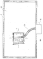
- eine Draufsicht auf die sich in einem Becken befindende Reinigungsvorrichtung nach Fig. 1 bis 3,
- Fig. 5
- eine alternative Ausbildung der Reinigungsvorrichtung nach Fig. 1 bis 3 mit seitlichem Abwurf,
- Fig. 6
- eine Reinigungsvorrichtung nach Fig. 1 bis 3 in Verbindung mit einer Rohrbrücke
- Fig. 1
- a plan view of a cleaning device,
- Fig. 2
- 2 shows a side view of the cleaning device according to FIG. 1,
- Fig. 3
- 2 shows a front view of the cleaning device shown in FIGS. 1 and 2,
- Fig. 4
- 2 shows a plan view of the cleaning device according to FIGS. 1 to 3 located in a basin,
- Fig. 5
- an alternative embodiment of the cleaning device according to FIGS. 1 to 3 with lateral discharge,
- Fig. 6
- a cleaning device according to FIGS. 1 to 3 in connection with a pipe bridge
Die in den Figuren 1 bis 3 dargestellte Reinigungsvorrichtung 1 weist eine Reinigungseinheit 2 sowie eine Verfahreinheit 3 auf, die gemeinsam eine auf einem Bodenteil,vorzugsweise einem Beckenboden selbstverfahrbare kompakte Baueinheit bilden.The
Die Verfahreinheit 3 enthält einen Fahrantrieb 5 zur Erzeugung der Verfahrbewegung durch als Laufräder 6 oder Raupenketten ausgebildete Verfahrelemente und ferner eine Fahrsteuereinrichtung 7.The
Die Reinigungsvorrichtung 1 ist zur Erkennung der Menge und des Ortes der angefallenen zu entfernenden Stoffe mit einem ersten Typ eines Sensors 8 (erster Sensor) versehen. Dieser erste Sensor ist zweckmäßig als optischer Sensor,beispielsweise als Infrarotsensor, ausgebildet. Ein zweiter Typ von Sensor 9 (zweiter Sensor) dient zur Feststellung der Konsistenz der zu entfernenden Stoffe. Dieser zweite Sensor kann beispielsweise zweckmäßig als akustischer Sensor, insbesondere als Schallreflexsensor nach dem Echolotprinzip ausgebildet sein. Grundsätzlich sind jedoch auch andere Sensoren möglich und gegebenenfalls zweckmäßig.The
Beide Sensoren sind mit dem Eingang einer Rechnereinheit 10 verbunden. Der Ausgang der Rechnereinheit 10 steuert den Fahrantrieb 5 unter Zwischenschaltung eines in der Zeichnung nicht dargestellten Signalverstärkers über die Fahrsteuereinrichtung 7. In einem Speicher der Recheneinheit 10 ist ein lernfähiges Expertensystem vorhanden.Both sensors are connected to the input of a
Die Reinigungseinheit 2 weist ein Schlammräumschild 16 auf, das sich an der Frontseite 17 der Reinigungsvorrichtung 1 befindet. An der Rückseite der Reinigungsvorrichtung 1 ist ein weiteres Schlammräumwerkzeug 16a vorgesehen, so daß die Reinigungsvorrichtung 1 in zwei Fahrtrichtungen räumen kann.The
Die Aufnahmeausnehmung des Schlammräumschildes 16 ist durch einen Schlauch 18 mit der Schlammabsaugvorrichtung 15 verbunden, und diese fördert den abgesaugten Schlamm vom Schlammräumschild 16 bzw. Räumwerkzeug 16a zu einem Anschlußadapter 19 der Reinigungsvorrichtung 1, an den ein weiterer Schlauch oder ein sonstiges Verbindungselement zur Weiterführung des Schlamms an eine Übergabestelle zur Entsorgung anschließbar ist.The receiving recess of the
In bestimmten Anwendungsfällen kann die Reinigungsvorrichtung 1 vorteilhaft mit einem Schlammzwischenspeicher versehen sein, welcher zweckmäßig zusätzlich so ausgebildet sein kann, daß die Abgabe des Schlamms nur an einer bestimmten Übergabestelle im Fahrweg der Reinigungsvorrichtung bevorzugt am Fahrwegende erfolgt.In certain applications, the
Die wasserempfindlichen Teile der Reinigungsvorrichtung 1 sind in einem wasserdichten Gehäuse 20 eingeschlossen, so daß die Reinigungsvorrichtung 1 ohne Gefahr für diese Teile voll tauchfähig ist.The water-sensitive parts of the
In Fig. 4 befindet sich die Reinigungsvorrichtung 1 auf der Beckensohle 22 in einem mit Wasser gefüllten Absetzbecken, in Form eines Längsbeckens 21. Dabei ist der Anschlußadapter 19 der Reinigungseinheit 2 zum Weitertransport von Schlamm durch einen flexiblen Schlauch 23 mit einer zentralen Übergabestelle 24 verbunden.4, the
Hat sich auf der Beckensohle 22 des Längsbeckens 21 Schlamm angesammelt, der nach Menge, Konsistenz, örtlicher Häufung oder nach anderen Parametern eine Reinigung der Beckensohle 22 notwendig macht, so wird dies von den Sensoren 8,9 selbsttätig erkannt und der Reinigungsvorgang eingeleitet. Die entsprechenden Ausgangssignale der Sensoren 8,9 gelangen als Führungsgrößen in die Rechnereinheit 10. Dort werden sie von dem Expertensystem zur Erzeugung von Rechnerausgangssignalen verwendet. Die an die Fahrsteuereinrichtung 7 zur Steuerung des Fahrantriebs 5 weitergeleiteten Rechnerausgangssignale werden vor allem unter dem Gesichtspunkt einer möglichst wirtschaftlichen Verfahrbewegung der Reinigungsvorrichtung 1 erzeugt. Das bedeutet im wesentlichen, daß die Verfahrwege und die Einsatzdauer möglichst kurz sein sollen. Dabei kann die Verfahrbewegung der Reinigungsvorrichtung 1 jede Richtung auf der Beckensohle 22 annehmen und die Geschwindigkeit der Verfahrbewegung läßt sich der örtlichen Häufung des Schlamms anpassen. Eine weitere bei dieser Ausführungsform nicht dargestellte Möglichkeit, auf unterschiedliche Mengen von abzusaugendem Schlamm zu reagieren, besteht in einer vorteilhaften Anpassung der Leistung der Absaugvorrichtung, die ebenfalls durch entsprechende Signale von der Rechnereinheit 10 gesteuert werden kann. Gegebenenfalls können in einer konstruktiven Lösung zur Bewältigung der örtlich unterschiedlichen Mengen an abzuscheidendem Schlamm beide Möglichkeiten kombiniert verwirklicht werden.If sludge has accumulated on the bottom of the
Wie aus Fig. 4 erkennbar ist, sind die Abmessungen der kompakten selbstverfahrbaren Reinigungsvorrichtung 1 bei weitem kleiner als die des Absetzbeckens 21. Da bei den Abmessungen der Reinigungsvorrichtung 1 keine Anpassung an die Beckenabmessungen erforderlich ist, ergibt sich der wesentliche Vorteil, daß die Reinigungsvorrichtung 1 nacheinander in mehreren auch unterschiedlichen Becken eingesetzt werden kann. So ist es beispielsweise ohne weiteres möglich, die Reinigungsvorrichtung 1 auch für ein Rundbecken oder für andere Beckenformen zu verwenden. Für das Entnehmen und das Einsetzen der Reinigungsvorrichtung 1 in verschiedene Becken kann beispielsweise ein mobiler Kran verwendet werden. In der Praxis hat es sich gezeigt, daß es eine Vielzahl von Anwendungsfällen gibt, in denen die Reinigungsintervalle für die einzelnen Becken groß genug sind, um eine einzige Reinigungsvorrichtung nacheinander in mehreren Becken zu verwenden. Dies hat für die Betreiber derartiger Anlagen große wirtschaftliche Bedeutung, da sie nunmehr nicht für jedes Becken eine eigene Reinigungsvorrichtung beschaffen und installieren müssen.As can be seen from FIG. 4, the dimensions of the compact self-propelled
Bei der Darstellung nach Fig. 5 wird ebenfalls die Reinigungsvorrichtung nach der in Fig. 1 dargestellten Ausführung benutzt. Hierbei ist am Anschlußadapter 19 ein teleskopartig in seiner Länge verstellbares Rohr 31 mit zugehörigem Verstellantrieb einseitig angeschlossen. Die Länge des verstellbaren Rohres 31 ist dabei so einzurichten, daß sich die Auslaßseite des Rohres 31 unabhängig von der Bewegung der Reinigungsvorrichtung 1 im Becken über einer entlang der Längskante 32 des Längsbeckens 30 parallel verlaufenden Übergabestelle in einer Rinne 33 befindet. In einer einfachen Ausbildung kann auf ein Verstellantrieb des Übergaberohres gegebenenfalls verzichtet werden, wenn die Auslaßseite des Rohres 31 eine mechanische Zwangsführung aufweist, welche dafür sorgt, daß die Rohrmündung stets über der Rinne 33 liegt.5, the cleaning device according to the embodiment shown in FIG. 1 is also used. Here, a telescopically
Bei der konstruktiven Lösung nach Fig. 6 ist die Reinigungsvorrichtung 1 längs einer Rohrbrücke 37 quer zur Beckenlängsrichtung verfahrbar. Die Längsbewegung wird der Reinigungsvorrichtung 1 durch die in Beckenlängsrichtung verfahrbare Rohrbrücke 37 übertragen.In the constructive solution according to FIG. 6, the
Die Rohrbrücke 37 ist auf in der Zeichnung nicht dargestellten Schienenführungen parallel zu den oberen Längskanten 40 des Längsbeckens 39 verfahrbar. Der Anschlußadapter 19 der Reinigungsvorrichtung 1 ist über einen Verbindungsschlauch 36 an die Rohrbrücke 37 angeschlossen. Dabei werden die abzuscheidenden Stoffe über den Schlauch 36 in den freien Innenraum des Rohres 38 oder einer entsprechenden Rinne auf der Rohrbrücke 37 abgegeben. Von dort gelangen sie analog der Ausbildung nach Fig. 5 in eine entlang der oberen Längskante 40 parallel verlaufende Rinne 41. Für bestimmte Anwendungsfälle ist auch die Anwendung von zwei Rinnen 41 möglich, welche jeweils parallel beidseitig zu den oberen Längskanten 40 des Längsbeckens 39 angeordnet sind. Die Steuerung der Fahrbewegung der Rohrbrücke 37 kann dabei ebenfalls von der Rechnereinheit 10 vorgenommen werden. Da die Rohrbrücke 37 zweckmäßig zusätzlich zur Erzeugung der Längsverfahrbewegung der Reinigungsvorrichtung 1 verwendet wird, muß die Verfahreinheit 3 der Reinigungsvorrichtung 1 lediglich entsprechende Querbewegungen zur Längsrichtung des Beckens 39 erzeugen.The
Die erfindungsgemäße Reinigungsvorrichtung nach Fig. 6 unterscheidet sich somit in ihrer Verbindung mit der Abgabestelle von den vorher beschriebenen Ausführungsformen. Alle übrigen Merkmale der in Fig. 1 bis 3 dargestellten Baueinheit, insbesondere bezüglich der Sensoren und der Rechnereinheit und der sich daraus ergebenden Möglichkeiten, sind auch in dieser erfindungsgemäßen Ausgestaltung verwirklicht.The cleaning device according to the invention according to FIG. 6 thus differs in its connection to the delivery point from the previously described embodiments. All other features of the structural unit shown in FIGS. 1 to 3, in particular with regard to the sensors and the computer unit and the possibilities resulting therefrom, are also realized in this embodiment according to the invention.
Bei einer anderen zweckmäßigen Ausbildung können ferner mehrere Reinigungsvorrichtungen 1 in einem Becken benutzt werden.In another expedient design, a plurality of
Claims (14)
- Device for cleaning a basin, in particular for removing sludge or sand, having a transportable cleaning device (1) for receiving the substances to be separated off and for carrying them onward to a transfer point for disposal, wherein the said cleaning device (1) has a cleaning unit (2) and a transporting unit (3) which is provided with a travel control arrangement (7) and a travel drive (5) for producing the transporting movement on the floor of the basin, and wherein at least one sensor is present for identifying the accumulated materials to be separated off, as a result of which a control unit triggers and controls the transporting movement in dependence upon the accumulation of the substances to be separated off, characterised in that at least one first sensor (8) for identifying the location, or the location and quantity, of the accumulated substances to be separated off is provided on the transportable cleaning device (1), and that a computer unit (10) further processes output signals from the first sensor (8) as a guide quantity for producing computer output signals for the travel control arrangement (7) for flexible transporting movement adapted to the location, or to the location and quantity, of the accumulated substances, as a result of which the cleaning device (1) can be transported, with the aid of its transporting unit (3), in different directions as an automatically transportable structural unit, according to the location of the aggregation of substances to be separated off.
- Device according to claim 1, characterised in that the computer unit (10) has artificial intelligence, as a result of which it emits to the travel control unit (7), in the case of identical starting situations, different control signals for optimising the transporting movement of the cleaning device (1).
- Device according to claim 1 or 2, characterised in that a second sensor (9) is provided for establishing the consistency of the substances to be removed, and is connected to the computer unit (10).
- Device according to claim 1, characterised in that the travel movement of the cleaning device (1) can be controlled by guide lines integrated into the basin.
- Device according to claim 4, characterised in that the said guide lines are orientated vertically and horizontally in relation to one another, in the form of a matrix.
- Device according to claim 1, characterised in that there is provided, for receiving the substances to be separated off, an extracting device, the suction power of which can be adapted, by the computer unit (10), to the differing quantities of the substances to be separated off.
- Device according to claim 1, characterised in that the cleaning device (1) is connected, for carrying the substances to be separated off onwards through a hose (23), to a central transfer point (24).
- Device according to claim 1, characterised in that there is provided, for delivering the substances received by the cleaning device (1), a transportable tubular bridge (37), with the aid of which the substances to be delivered are delivered into a channel (33) disposed at the edge of the basin on at least one side.
- Device according to claim 1, characterised in that the cleaning device (1) is in communication with a tube (31) of variable length above a channel disposed parallel to the edge of the basin.
- Device according to claim 5 or 6, characterised in that the cleaning device (1) has at least two sludge-clearing tools (16, 16a) or sludge-extracting devices which operate in different directions of travel.
- Device according to claim 1, characterised in that the cleaning device (1) contains an intermediate reservoir for the substances to be separated off.
- Device according to claim 11, characterised in that the delivery, from the intermediate reservoir to a defined transfer point, of the substances to be separated off takes place in dependence upon the path of travel of the cleaning device (1).
- Device according to claim 10, characterised in that the transportable cleaning device (1) is provided with at least one clearing plate (16, 16a) which operates on the floor of the basin, and that at least one receiving funnel is provided at the transfer point in the floor of the basin.
- Device according to claim 1, characterised in that at least two sensor-controlled cleaning devices (1) are movably disposed on a transverse bridge submerged in the basin, in such a way that an assigned cleaning area, in each case, is swept by each cleaning device (1).
Applications Claiming Priority (2)
| Application Number | Priority Date | Filing Date | Title |
|---|---|---|---|
| DE4304375A DE4304375A1 (en) | 1993-02-13 | 1993-02-13 | Device for cleaning a basin |
| DE4304375 | 1993-02-13 |
Publications (2)
| Publication Number | Publication Date |
|---|---|
| EP0613708A1 EP0613708A1 (en) | 1994-09-07 |
| EP0613708B1 true EP0613708B1 (en) | 1997-07-02 |
Family
ID=6480392
Family Applications (1)
| Application Number | Title | Priority Date | Filing Date |
|---|---|---|---|
| EP94101866A Expired - Lifetime EP0613708B1 (en) | 1993-02-13 | 1994-02-08 | Device for cleaning a basin |
Country Status (3)
| Country | Link |
|---|---|
| EP (1) | EP0613708B1 (en) |
| AT (1) | ATE154889T1 (en) |
| DE (2) | DE4304375A1 (en) |
Families Citing this family (1)
| Publication number | Priority date | Publication date | Assignee | Title |
|---|---|---|---|---|
| DE102009040958A1 (en) * | 2009-09-11 | 2011-03-17 | Holger Pinta | Method for controlling scraper operation of longitudinal grit trap for mechanically cleaning e.g. local area waste water, involves determining fit capacity of mineral settleable material by diffusion control of flow of material |
Family Cites Families (5)
| Publication number | Priority date | Publication date | Assignee | Title |
|---|---|---|---|---|
| JPS5992006A (en) * | 1982-11-19 | 1984-05-28 | Mitsubishi Electric Corp | Apparatus for controlling waste sludge of precipitation basin in water purification plant |
| JPS6261604A (en) * | 1985-09-11 | 1987-03-18 | Toshiba Corp | Sludge scrape-up apparatus |
| DE3715021A1 (en) * | 1987-05-06 | 1988-11-17 | Geiger Maschf Helmut | Rake for a circular sedimentation tank |
| US5269041A (en) * | 1990-06-13 | 1993-12-14 | Allen Henry W | Remote controlled sludge removal apparatus |
| DE4100309A1 (en) * | 1991-01-08 | 1992-07-09 | Passavant Werke | Cleaning unit for long basins or mine channels - comprises floating sludge tank joined to pump assembly by flexible linkage, for sludge removal at fixed intervals |
-
1993
- 1993-02-13 DE DE4304375A patent/DE4304375A1/en not_active Ceased
-
1994
- 1994-02-08 DE DE59403235T patent/DE59403235D1/en not_active Expired - Fee Related
- 1994-02-08 AT AT94101866T patent/ATE154889T1/en not_active IP Right Cessation
- 1994-02-08 EP EP94101866A patent/EP0613708B1/en not_active Expired - Lifetime
Also Published As
| Publication number | Publication date |
|---|---|
| DE59403235D1 (en) | 1997-08-07 |
| EP0613708A1 (en) | 1994-09-07 |
| DE4304375A1 (en) | 1994-08-18 |
| ATE154889T1 (en) | 1997-07-15 |
Similar Documents
| Publication | Publication Date | Title |
|---|---|---|
| EP0457951B1 (en) | Device for the flow separation of oil from water with flow in meander form | |
| DE2356697C2 (en) | Device for separating sludge flakes from a carrier liquid | |
| DE2743963C2 (en) | Device for separating substances from contaminated water | |
| DE1642432B2 (en) | PURIFICATION AND FILTER SYSTEM | |
| DE2707872C2 (en) | ||
| EP0596052B1 (en) | Method and inlet device for feeding flat sand traps and settling tanks/secondary settler | |
| DE2401550A1 (en) | DEVICE FOR SLUDGE REMOVAL | |
| DE2726217A1 (en) | METHOD AND DEVICE FOR REMOVING SLUDGE | |
| DE2706642A1 (en) | DEVICE FOR SEPARATING TWO LIQUIDS OF DIFFERENT SPECIFIC WEIGHT | |
| EP0613708B1 (en) | Device for cleaning a basin | |
| DE2929139A1 (en) | Cyclonic separator for water streams - to removed suspended material using centrifugal action to separate less dense solids from liq stream and run them off via separate duct | |
| DE2940926A1 (en) | Sludge settling tank emptying system - uses variably controlled siphon tubes system | |
| DE102008038003A1 (en) | Device for straightening and sorting empty vessel in empty-reverse vending machine, has guide unit for guiding empty container from horizontal orientation in increased conveying level into upright orientation in lower conveying level | |
| WO2000026141A1 (en) | Compact installation for mechanically cleaning waste water | |
| DE4407343A1 (en) | Apparatus for separating off particles having solid consistency from a liquid | |
| DE3426742A1 (en) | Apparatus for sludge water discharge for sewage sludge thickeners | |
| DE4440707B4 (en) | Device for cleaning contaminated soil | |
| DE19726745B4 (en) | Method for separating particles | |
| DE3011339C2 (en) | Process for cleaning the tubes of a power plant condenser and device for carrying out the process | |
| DE1907432C3 (en) | Equipment for sludge suction clearing in a rectangular settling basin | |
| DE2154216A1 (en) | Inclined plate clarifier - for separation of solids from liquid suspensions | |
| DD220074B1 (en) | DEVICE FOR DRAINING SEPARATOR PLANTS, IN PARTICULAR FATS AND ABSORBENT LUBRICANTS | |
| DE3149505C2 (en) | Method and device for filling a sump | |
| EP0508047A1 (en) | Purifier for waste water | |
| EP1806181A1 (en) | Method and device for processing gravel, sand or similar |
Legal Events
| Date | Code | Title | Description |
|---|---|---|---|
| PUAI | Public reference made under article 153(3) epc to a published international application that has entered the european phase |
Free format text: ORIGINAL CODE: 0009012 |
|
| AK | Designated contracting states |
Kind code of ref document: A1 Designated state(s): AT BE CH DE FR GB LI |
|
| 17P | Request for examination filed |
Effective date: 19941216 |
|
| 17Q | First examination report despatched |
Effective date: 19951222 |
|
| GRAG | Despatch of communication of intention to grant |
Free format text: ORIGINAL CODE: EPIDOS AGRA |
|
| GRAG | Despatch of communication of intention to grant |
Free format text: ORIGINAL CODE: EPIDOS AGRA |
|
| GRAG | Despatch of communication of intention to grant |
Free format text: ORIGINAL CODE: EPIDOS AGRA |
|
| GRAH | Despatch of communication of intention to grant a patent |
Free format text: ORIGINAL CODE: EPIDOS IGRA |
|
| GRAH | Despatch of communication of intention to grant a patent |
Free format text: ORIGINAL CODE: EPIDOS IGRA |
|
| GRAA | (expected) grant |
Free format text: ORIGINAL CODE: 0009210 |
|
| AK | Designated contracting states |
Kind code of ref document: B1 Designated state(s): AT BE CH DE FR GB LI |
|
| REF | Corresponds to: |
Ref document number: 154889 Country of ref document: AT Date of ref document: 19970715 Kind code of ref document: T |
|
| REG | Reference to a national code |
Ref country code: CH Ref legal event code: EP |
|
| REF | Corresponds to: |
Ref document number: 59403235 Country of ref document: DE Date of ref document: 19970807 |
|
| GBT | Gb: translation of ep patent filed (gb section 77(6)(a)/1977) |
Effective date: 19970717 |
|
| ET | Fr: translation filed | ||
| REG | Reference to a national code |
Ref country code: CH Ref legal event code: NV Representative=s name: A. BRAUN, BRAUN, HERITIER, ESCHMANN AG PATENTANWAE |
|
| PLBE | No opposition filed within time limit |
Free format text: ORIGINAL CODE: 0009261 |
|
| STAA | Information on the status of an ep patent application or granted ep patent |
Free format text: STATUS: NO OPPOSITION FILED WITHIN TIME LIMIT |
|
| 26N | No opposition filed | ||
| REG | Reference to a national code |
Ref country code: GB Ref legal event code: IF02 |
|
| PGFP | Annual fee paid to national office [announced via postgrant information from national office to epo] |
Ref country code: GB Payment date: 20020129 Year of fee payment: 9 |
|
| PGFP | Annual fee paid to national office [announced via postgrant information from national office to epo] |
Ref country code: BE Payment date: 20020205 Year of fee payment: 9 |
|
| PGFP | Annual fee paid to national office [announced via postgrant information from national office to epo] |
Ref country code: CH Payment date: 20020218 Year of fee payment: 9 |
|
| PGFP | Annual fee paid to national office [announced via postgrant information from national office to epo] |
Ref country code: AT Payment date: 20020227 Year of fee payment: 9 |
|
| PGFP | Annual fee paid to national office [announced via postgrant information from national office to epo] |
Ref country code: DE Payment date: 20020304 Year of fee payment: 9 |
|
| PG25 | Lapsed in a contracting state [announced via postgrant information from national office to epo] |
Ref country code: FR Free format text: LAPSE BECAUSE OF NON-PAYMENT OF DUE FEES Effective date: 20021031 |
|
| REG | Reference to a national code |
Ref country code: FR Ref legal event code: ST |
|
| PG25 | Lapsed in a contracting state [announced via postgrant information from national office to epo] |
Ref country code: GB Free format text: LAPSE BECAUSE OF NON-PAYMENT OF DUE FEES Effective date: 20030208 Ref country code: AT Free format text: LAPSE BECAUSE OF NON-PAYMENT OF DUE FEES Effective date: 20030208 |
|
| PG25 | Lapsed in a contracting state [announced via postgrant information from national office to epo] |
Ref country code: LI Free format text: LAPSE BECAUSE OF NON-PAYMENT OF DUE FEES Effective date: 20030228 Ref country code: CH Free format text: LAPSE BECAUSE OF NON-PAYMENT OF DUE FEES Effective date: 20030228 Ref country code: BE Free format text: LAPSE BECAUSE OF NON-PAYMENT OF DUE FEES Effective date: 20030228 |
|
| PGFP | Annual fee paid to national office [announced via postgrant information from national office to epo] |
Ref country code: FR Payment date: 20030314 Year of fee payment: 10 |
|
| REG | Reference to a national code |
Ref country code: FR Ref legal event code: RN |
|
| PG25 | Lapsed in a contracting state [announced via postgrant information from national office to epo] |
Ref country code: DE Free format text: LAPSE BECAUSE OF NON-PAYMENT OF DUE FEES Effective date: 20030902 |
|
| GBPC | Gb: european patent ceased through non-payment of renewal fee | ||
| REG | Reference to a national code |
Ref country code: CH Ref legal event code: PL |
|
| REG | Reference to a national code |
Ref country code: FR Ref legal event code: IC |