EP0613402B1 - Poignee de liberation pour ensemble couvercle et rotor centrifuge - Google Patents
Poignee de liberation pour ensemble couvercle et rotor centrifuge Download PDFInfo
- Publication number
- EP0613402B1 EP0613402B1 EP93922742A EP93922742A EP0613402B1 EP 0613402 B1 EP0613402 B1 EP 0613402B1 EP 93922742 A EP93922742 A EP 93922742A EP 93922742 A EP93922742 A EP 93922742A EP 0613402 B1 EP0613402 B1 EP 0613402B1
- Authority
- EP
- European Patent Office
- Prior art keywords
- knob
- lid
- spindle
- rotor
- centrifuge
- Prior art date
- Legal status (The legal status is an assumption and is not a legal conclusion. Google has not performed a legal analysis and makes no representation as to the accuracy of the status listed.)
- Expired - Lifetime
Links
- 230000008878 coupling Effects 0.000 claims description 7
- 238000010168 coupling process Methods 0.000 claims description 7
- 238000005859 coupling reaction Methods 0.000 claims description 7
- 238000005119 centrifugation Methods 0.000 abstract description 23
- 230000008901 benefit Effects 0.000 abstract description 2
- 238000007789 sealing Methods 0.000 description 6
- 239000004677 Nylon Substances 0.000 description 3
- 239000004809 Teflon Substances 0.000 description 3
- 229920006362 Teflon® Polymers 0.000 description 3
- 229920001778 nylon Polymers 0.000 description 3
- 125000006850 spacer group Chemical group 0.000 description 3
- 238000000034 method Methods 0.000 description 2
- 239000000443 aerosol Substances 0.000 description 1
- AIYUHDOJVYHVIT-UHFFFAOYSA-M caesium chloride Chemical compound [Cl-].[Cs+] AIYUHDOJVYHVIT-UHFFFAOYSA-M 0.000 description 1
- 230000000694 effects Effects 0.000 description 1
- 230000007246 mechanism Effects 0.000 description 1
- 238000012986 modification Methods 0.000 description 1
- 230000004048 modification Effects 0.000 description 1
- 230000036316 preload Effects 0.000 description 1
- 230000002035 prolonged effect Effects 0.000 description 1
- 230000009467 reduction Effects 0.000 description 1
- 230000000717 retained effect Effects 0.000 description 1
Images
Classifications
-
- B—PERFORMING OPERATIONS; TRANSPORTING
- B04—CENTRIFUGAL APPARATUS OR MACHINES FOR CARRYING-OUT PHYSICAL OR CHEMICAL PROCESSES
- B04B—CENTRIFUGES
- B04B7/00—Elements of centrifuges
- B04B7/02—Casings; Lids
-
- B—PERFORMING OPERATIONS; TRANSPORTING
- B04—CENTRIFUGAL APPARATUS OR MACHINES FOR CARRYING-OUT PHYSICAL OR CHEMICAL PROCESSES
- B04B—CENTRIFUGES
- B04B5/00—Other centrifuges
- B04B5/04—Radial chamber apparatus for separating predominantly liquid mixtures, e.g. butyrometers
- B04B5/0407—Radial chamber apparatus for separating predominantly liquid mixtures, e.g. butyrometers for liquids contained in receptacles
- B04B5/0414—Radial chamber apparatus for separating predominantly liquid mixtures, e.g. butyrometers for liquids contained in receptacles comprising test tubes
-
- B—PERFORMING OPERATIONS; TRANSPORTING
- B04—CENTRIFUGAL APPARATUS OR MACHINES FOR CARRYING-OUT PHYSICAL OR CHEMICAL PROCESSES
- B04B—CENTRIFUGES
- B04B7/00—Elements of centrifuges
- B04B7/02—Casings; Lids
- B04B2007/025—Lids for laboratory centrifuge rotors
-
- F—MECHANICAL ENGINEERING; LIGHTING; HEATING; WEAPONS; BLASTING
- F16—ENGINEERING ELEMENTS AND UNITS; GENERAL MEASURES FOR PRODUCING AND MAINTAINING EFFECTIVE FUNCTIONING OF MACHINES OR INSTALLATIONS; THERMAL INSULATION IN GENERAL
- F16B—DEVICES FOR FASTENING OR SECURING CONSTRUCTIONAL ELEMENTS OR MACHINE PARTS TOGETHER, e.g. NAILS, BOLTS, CIRCLIPS, CLAMPS, CLIPS OR WEDGES; JOINTS OR JOINTING
- F16B2200/00—Constructional details of connections not covered for in other groups of this subclass
- F16B2200/40—Clamping arrangements where clamping parts are received in recesses of elements to be connected
- F16B2200/403—Threaded clamping parts
Definitions
- the present invention relates to centrifugation, and more particularly to centrifuge rotors and lids.
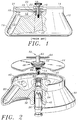
- Fig. 1 shows the sectional view of a prior art "fixed angle" centrifuge rotor 10.
- the rotor has an axially symmetric body provided with several cavities 12 about the rotor axis. Each cavity is sized and shaped to receive a centrifuge tube 13 containing the sample to be centrifuged.
- a lid 14 is provided to cover the opening 15 of the rotor to contain aerosol.
- a lid knob 16 having a threaded end is provided for bolting the lid 14 on the rotor 10.
- a spindle knob 18 having a shaft is provided for bolting the rotor 10 to the spindle 20 of a centrifuge drive.
- Several O-ring seals 21-24 are provided for sealing adjoining structures as shown.
- the rotor Prior to centrifugation, the rotor is positioned on a laboratory bench and centrifuge tubes 13 containing samples are loaded into the rotor cavities 12. Typically, there may be locking and sealing mechanisms for each cavity (not shown).
- the lid 14 is placed to cover the rotor opening 15 and the lid knob 16 is hand tightened to secure the lid 14 on the rotor 10.
- the rotor is then carried to the centrifuge and lowered onto the spindle 20.
- the spindle knob 18 is hand tightened to secure the rotor hub against the spindle.
- the rotor may be used in a centrifuge which draws a vacuum in the centrifuge chamber.
- a centrifuge which draws a vacuum in the centrifuge chamber.
- one approach to centrifugation is to suspend the sample in a cesium chloride density gradient forming solution, a technique well known in the art. Upon centrifugation, the sample components separate into regions or bands parallel to the axis of rotation, and at distances from the axis depending on their relative densities.
- the pressure difference gives rise to a large force on the upper surface of the lid which presses the lid tightly against the rotor.
- this force is overpowering against the hand turning torque of a typical user.
- the user had to use a tool (e.g. a wrench) to provide the additional torque required.
- Another cause for the increased tightening of the lid knob after centrifugation arises from the increased friction at the O-ring seals and the threads between the lid knob and rotor body as affected by centrifugation (parts expand during centrifugation and contract after centrifugation at different rates).
- a further centrifuge rotor is known from EP-A-0054744 and comprises a swinging bucket type centrifuge having a domed cover which entirely surrounds the centrifuge, a handle being mounted on the cover through an opening coaxial with the axis of the rotor.
- a locking shaft is insertable through registered openings in the handle to secure the rotor to the shaft of the centrifuge to supply motive energy for rotating the rotor.
- centrifuge rotor comprising:
- centrifuge rotor comprising:
- the upper end of the inner knob is provided with a handle which extends perpendicular to the axis of the knob.
- This handle is used for lifting the rotor after the spindle knob has been unscrewed from the spindle and for unscrewing the lid knob.
- the handle provides the necessary mechanical advantage for a person to exert sufficient torque to unscrew the lid knob, thus avoiding the need for an external tool such as wrenches.
- Fig. 1 is a partial sectional view of a prior art centrifuge rotor.
- Fig. 2 is a exploded perspective view (partially broken away) of a centrifuge rotor and lid assembly in accordance with one embodiment of the present invention.
- Fig. 3 is a sectional view of the rotor and lid assembly of Fig. 2.
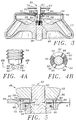
- Fig. 4A is a side view of the tip of the lid lock
- Fig. 4B is a bottom view of the lid lock taken along line 4B-4B in Fig. 4A.
- Fig. 5 is a sectional view showing the details at the coupling between the lid and the knobs.
- a centrifuge rotor 30 which has a number of cavities 32 shaped and sized for receiving centrifuge tubes.
- an adaptor 34 is inserted for fitting onto a spindle 36 of a centrifuge drive (not shown).
- Dowel pins 38 are provided on the adaptor 34 for positive engagement with the cutouts 40 on the spindle 36.
- a lid 44 is sized to fit over the opening 42.
- An O-ring 46 is provided at the rim of the lid for sealing the lid to the rotor opening.
- a lid knob 48 and a spindle knob 50 are coaxially coupled through the center of the lid. The knobs are free to rotate and slidable relative to each other.
- the lid knob 48 has an enlarged end 52 and a threaded end 54 for bolting onto the raised central portion 56 of the rotor to securely cover the rotor with the lid 44.
- the spindle knob 50 is longer than and extends coaxially through the lid knob 48.
- the spindle knob 50 has a shaft 58 having a threaded end 60 and an end 62 having a horizontal handle 64 extending perpendicular to the shaft 58.
- the threaded end 60 is for bolting to the centrifuge drive spindle 36 to secure the rotor on the spindle.
- a pin 66 is inserted through the side of the shaft 58 above the threaded end 60.
- the lid knob 48 has a split retaining ring 68 which biases radially inward under its spring force.
- This retaining ring 68 sits in a groove 70 in the lid knob 48 and it retains attachment of the lid knob 48 onto the lid 44.
- a split retaining ring 72 which biases radially outward under its spring force is press fitted into the lid 44 at the region about the retaining ring 68.
- a belleville spring washer 74 is provided between the flange of the spindle knob 50 and the flange of the lid knob 48. This washer generates a preload when the spindle knob 50 is tightened on the spindle 36, so as to prevent the rotor from detaching from the spindle 36 as a result of rotor vibration during centrifugation.
- a teflon spacer 76 is provided under the enlarged end 52 of the lid knob 48, which will reduce the friction when the lid knob is in rotational contact with the top of the lid 44.
- Two vent holes 78 and 80 are provided on the lid 44 below the enlarged end 52 of the lid knob 48.
- a nylon insert (82, 84) is pressed into a counterbore (86, 88) at the top surface of the lid 44.
- the lid knob 48 is tightened, the teflon spacer 76 and the nylon inserts 82 and 84 seal the vent holes 78 and 80.
- the function of the vent holes will be more apparent below.
- Around the raised center portion 56 is a channel provided with an O-ring 90 for further sealing of the lid 44.
- the tip of the threaded end 54 of the lid knob 48 has a surface structure which provides uni-direction rotational engagement with the pin 66 on the spindle knob 50.
- This pin 66 will cooperatively engage with the uni-directional structure on the tip of the lid knob 48.
- the bottom surface of the threaded end 54 of the lid lock 48 has two ridges 92 and 93 occupying two sectors of the tip annulus.
- Each ridge has a gentle slope or cam surface (94, 95) on one side of the ridge and a shoulder (96, 99) (may be a steep or vertical slope, or a recessed edge) on the other side.
- the pin 66 will slide over the slopes 94 and 95 when the shaft 58 of the spindle knob 50 is turned towards the slopes. However, the pin 66 will latch against the shoulders 96 and 99 when the shaft 58 is turned towards the shoulders. There are two flat sectors 97 and 98 between the ridges 92 and 93.
- the rotor 10 is typically set on a laboratory bench while centrifuge tubes containing samples to be centrifuged are loaded into the rotor cavities 32.
- the lid 44 is placed over the rotor opening 42 and the lid knob 48 is hand tightened onto the central portion 56 of the rotor.
- the spindle 36 rotates counterclockwise when viewed from the top.
- the lid knob 48 therefore is configured to be tightened clockwise.
- the rotor is moved to the centrifuge by conveniently lifting on the handle 64.
- the rotor 30 is lowered onto the spindle 36 in the centrifuge and the handle 64 is turned by hand to tighten the spindle knob 60.
- the length of the shaft 58 of the spindle knob 50 is chosen in relation to the spindle 36 such that unless the lid knob 48 has been properly seated on the rotor 30 and tightened, and that the rotor 30 has been properly seated onto the spindle 36 with the pins 38 located in the cutouts 40 of the spindle 36, the end 60 of the spindle knob 50 will not reach the internal threads on the spindle 36. This provides an additional safeguard to ensure that the rotor 30 and lid 44 have been seated properly by the user before beginning centrifugation.
- the rotor is used in a centrifuge which draws a vacuum inside the centrifuge chamber to reduce aerodynamic friction at high speed operations. During centrifugation, some of the air under the rotor lid 44 may escape into the vacuum outside of the rotor.
- the vacuum is released in the centrifuge. It is noted that the inside of the rotor may still be under partial vacuum. The imbalance in atmospheric pressure therefore exerts a force on the lid.
- the handle 64 is turned counterclockwise to completely loosen the spindle knob 50 from the spindle threads. At this stage, the pin 66 on the shaft 58 of the spindle knob is just below the uni-direction structure at the bottom tip of the lid knob 48. Further turning in the counterclockwise direction does not engage the pin 66 against the structure, unless the spindle knob 50 is lifted and turned.
- the handle 64 is lifted to remove the rotor from the centrifuge and move the rotor to a bench. As the handle is lifted, the pin 66 will always end up in contact with the flat spots 97 and 98 at the bottom end of the lid knob 48 because of the pin 66 slipping on the cam surfaces 94 and 95. Since the handle 64 is coupled to the spindle knob 50 which is vertically in line with the center of mass of the rotor 30, and the rotor center of mass is low compared to the vertical location of the handle, there is a tendency for the massive rotor to remain stabilized under its own weight when it is moved about by the handle 64. Consequently, the separated sample components in the rotor are not disturbed as to cause mixing.
- the handle 64 is lifted and the spindle knob 50 is turned counterclockwise.
- the pin 66 on the spindle knob 50 cooperatively engages the shoulders 96 and 99 of the unidirectional structure at the bottom end of the lid knob 48 so as to turn the lid knob 48 in a counterclockwise direction, thereby loosening the spindle knob 50.
- the seals at the vent holes 78 and 80 are broken as the enlarged end 52 of the lid knob rises above the lid 44. This causes the pressure on both sides of the lid to equalize.
- vent holes 78 and 80 on the lid 44 may be omitted entirely.
- the length of the handle 64 may be sized to provide the leverage for exerting the torque necessary to overcome the high atmospheric pressure force on the lid and other frictional resistance. However, when the vent holes are provided, less torque is needed to be exerted on the spindle knob 50 thereby extending the wear on this component.
- the handle 64 may be an integral or fixedly attached part of the spindle knob 50, or it may be a separate and removable part. The handle may be inserted through a through-hole in the spindle knob 50 when lifting of the rotor or untightening of the spindle and lid knobs are desired.
Landscapes
- Centrifugal Separators (AREA)
Claims (11)
- Rotor centrifuge (30) comportant :un corps de rotor définissant des cavités (32) pour recevoir des échantillons à centrifuger ;un couvercle (44) couvrant le sommet du corps de rotor ;un bouton de couvercle (48) accouplé au centre du couvercle pour fixer le couvercle au corps de rotor ;un bouton de broche (50) pour fixer le corps de rotor à une broche (36) d'une centrifugeuse, le bouton de broche étant coaxial et pouvant coulisser à travers le bouton de couvercle, caractérisé en ce que :le bouton de broche comporte un premier moyen d'engagement pour faire tourner de manière coopérative le bouton de couvercle seulement lorsque le bouton de broche est entraîné en rotation dans une direction prédéterminée autour d' un axe ; etle bouton de couvercle comporte un deuxième moyen d'engagement pour agir de manière coopérative avec ledit premier moyen d'engagement afin de permettre au bouton de broche de faire tourner le bouton de couvercle lorsque le bouton de broche est entraîné en rotation dans ladite direction prédéterminée.
- Rotor centrifuge selon la revendication 1, dans lequel le deuxième moyen d'engagement comporte une structure à nervures (92, 93) à une extrémité du bouton de couvercle, ladite structure à nervures présentant d'un côté un épaulement (96, 99) orienté dans une direction opposée à ladite direction prédéterminée, et dans lequel le premier moyen d'engagement comporte une structure à une extrémité du bouton de broche qui est configurée pour être mise en prise avec l'épaulement lorsque le bouton de broche est tourné dans ladite direction prédéterminée.
- Rotor centrifuge selon la revendication 2, dans lequel le deuxième moyen d'engagement comporte en outre une surface de came (94, 95) sur un côté de la nervure opposé à l'épaulement, par quoi ladite structure sur ledit bouton de broche glisse sur la surface de came lorsque le bouton de broche est tourné dans une direction opposée à ladite direction prédéterminée.
- Rotor centrifuge selon la revendication 2, dans lequel le bouton de broche et le bouton de couvercle sont structurés de façon que ladite extrémité du bouton de broche s'étende au-delà de ladite extrémité du bouton de couvercle de telle sorte que le bouton de broche peut coulisser relativement au bouton de couvercle pour amener l'extrémité de l'arbre de broche vers l'extrémité du bouton de couvercle.
- Rotor centrifuge selon la revendication 1, dans lequel le bouton de couvercle présente une extrémité agrandie et le couvercle comporte un trou d'aération (78, 80) qui se trouve sur le couvercle en dessous de ladite extrémité agrandie par quoi le bouton de couvercle rend étanche ledit trou d'aération lorsque le bouton de couvercle est serré sur le couvercle et le corps de rotor.
- Rotor centrifuge selon la revendication 1, dans lequel le bouton de broche comporte une poignée (64) s'étendant du bouton de broche pour réaliser un effet de levier pour faire tourner le bouton de broche.
- Rotor centrifuge (30) comportant :un corps de rotor définissant des cavités (32) pour recevoir des échantillons à centrifuger ;un couvercle (44) couvrant le dessus du corps de rotor ;un bouton de couvercle (48) accouplé au centre du couvercle pour fixer le couvercle sur le corps de rotor ;un bouton de broche (50) pour fixer le corps de rotor à une broche (36) d'une centrifugeuse, le bouton de broche étant coaxial et pouvant coulisser à travers le bouton de couvercle, caractérisé en ce que le rotor centrifuge comporte en outre un moyen d'accouplement situé entre le bouton de broche et le bouton de couvercle pour faire tourner de manière coopérative le bouton de couvercle seulement lorsque le bouton de broche est entraîné en rotation dans une direction prédéterminée autour d'un axe.
- Rotor centrifuge selon la revendication 7, dans lequel le moyen d'accouplement inclut une structure à nervures (92, 93) à une extrémité du bouton de couvercle, ladite structure à nervures présentant d'un côté un épaulement (96, 99) orienté dans une direction opposée à ladite direction prédéterminée, et le moyen d'accouplement comporte en outre une structure à une extrémité du bouton de broche qui est configurée pour venir en prise avec l'épaulement lorsque le bouton de broche est tourné dans ladite direction prédéterminée.
- Rotor centrifuge selon la revendication 8, dans lequel le moyen d'accouplement comporte en outre une surface de came (94, 95) sur un côté de la nervure opposée à l'épaulement, par quoi ladite structure sur ledit bouton de broche glisse sur la surface de came lorsque le bouton de broche est tourné dans une direction opposée à ladite direction prédéterminée.
- Rotor centrifuge selon la revendication 8, dans lequel le bouton de broche et le bouton de couvercle sont structurés de telle manière que ladite extrémité du bouton de broche s'étend au-delà de ladite extrémité du bouton de couvercle de telle sorte que le bouton de broche peut coulisser relativement au bouton de couvercle pour amener l'extrémité de l'arbre de broche vers l'extrémité du bouton de couvercle.
- Rotor centrifuge selon la revendication 10, dans lequel le bouton de couvercle comporte une extrémité agrandie, et le couvercle comporte un trou d'aération (78, 80) qui se trouve sur le couvercle en dessous de ladite extrémité agrandie par quoi ledit bouton de couvercle rend étanche ledit trou d'aération lorsque le bouton de couvercle est serré sur le couvercle et le corps de rotor.
Applications Claiming Priority (3)
| Application Number | Priority Date | Filing Date | Title |
|---|---|---|---|
| US954212 | 1992-09-30 | ||
| US07/954,212 US5344380A (en) | 1992-09-30 | 1992-09-30 | Release handle for centrifuge rotor and lid |
| PCT/US1993/009127 WO1994007606A1 (fr) | 1992-09-30 | 1993-09-27 | Poignee de liberation pour ensemble couvercle et rotor centrifuge |
Publications (2)
| Publication Number | Publication Date |
|---|---|
| EP0613402A1 EP0613402A1 (fr) | 1994-09-07 |
| EP0613402B1 true EP0613402B1 (fr) | 1997-06-04 |
Family
ID=25495098
Family Applications (1)
| Application Number | Title | Priority Date | Filing Date |
|---|---|---|---|
| EP93922742A Expired - Lifetime EP0613402B1 (fr) | 1992-09-30 | 1993-09-27 | Poignee de liberation pour ensemble couvercle et rotor centrifuge |
Country Status (6)
| Country | Link |
|---|---|
| US (1) | US5344380A (fr) |
| EP (1) | EP0613402B1 (fr) |
| JP (1) | JP3010222B2 (fr) |
| AT (1) | ATE153882T1 (fr) |
| DE (1) | DE69311299T2 (fr) |
| WO (1) | WO1994007606A1 (fr) |
Families Citing this family (46)
| Publication number | Priority date | Publication date | Assignee | Title |
|---|---|---|---|---|
| US5487719A (en) * | 1994-01-14 | 1996-01-30 | Denver Instrument Company | Centrifuge rotor assembly |
| EP0762940A1 (fr) * | 1994-06-15 | 1997-03-19 | Massachusetts Institute Of Technology | Ensemble formant element de recouvrement de rotor de centrifuge a verrouillage |
| US5512030A (en) * | 1994-12-01 | 1996-04-30 | E. I. Du Pont De Nemours And Company | Centrifuge rotor |
| US5605529A (en) * | 1996-01-17 | 1997-02-25 | Norfolk Scientific, Inc. | High efficiency centrifuge rotor |
| FR2770154B1 (fr) * | 1997-10-23 | 1999-11-26 | Jouan | Centrifugeuse a rotor demontable et a dispositif de blocage axial du rotor sur une tete d'entrainement, et rotor pour une telle centrifugeuse |
| US5897482A (en) * | 1998-03-04 | 1999-04-27 | Beckman Instruments, Inc. | Rotor lid tie-down and vacuum venting system |
| US6024687A (en) * | 1998-05-06 | 2000-02-15 | Beckman Coulter, Inc. | Centrifuge rotor lock |
| US6149570A (en) * | 1999-02-23 | 2000-11-21 | Beckman Coulter, Inc. | Self-retaining rotor lid |
| DE10164272C2 (de) * | 2001-12-27 | 2003-11-06 | Sigma Laborzentrifugen Gmbh | Verriegelungseinrichtung für den Deckel des Gehäuses einer Laborzentrifuge |
| US6665924B2 (en) * | 2002-01-25 | 2003-12-23 | Kendro Laboratory Products, L.P. | Centrifuge having a spring-loaded nut for securing a rotor to a drive cone |
| US6776751B2 (en) * | 2002-04-22 | 2004-08-17 | Kendor Laboratory Products, Lp | Rotor cover attachment apparatus |
| US7081081B2 (en) * | 2002-04-22 | 2006-07-25 | Kendro Laboratory Products, Lp | Bayonet coupling mechanism for a centrifuge |
| US6802803B2 (en) * | 2002-04-22 | 2004-10-12 | Kendro Laboratory Products, Inc. | Cover attachment apparatus |
| US6764438B2 (en) * | 2002-04-22 | 2004-07-20 | Kendro Laboratory Products, Lp | Cover attachment apparatus |
| US7011618B2 (en) * | 2003-05-16 | 2006-03-14 | Kendro Laboratory Products Lp | Attachment and release apparatus for a centrifuge rotor cover |
| DE102005014218B4 (de) * | 2005-03-29 | 2008-03-06 | Thermo Electron Led Gmbh | Befestigungsvorrichtung eines Deckels für einen Zentrifugenrotor |
| US7407296B2 (en) * | 2005-06-10 | 2008-08-05 | Infocus Corporation | Integrated light gathering reflector and optical element holder |
| JP4809474B2 (ja) * | 2006-05-23 | 2011-11-09 | エッペンドルフ アクチエンゲゼルシャフト | 遠心ロータの閉鎖用カバー |
| US7837607B2 (en) * | 2006-12-13 | 2010-11-23 | Thermo Fisher Scientific Inc. | Centrifuge rotor assembly and method of connection thereof |
| EP2214025B1 (fr) * | 2007-10-29 | 2018-12-26 | PHC Holdings Corporation | Dispositif d'analyse et appareil d'analyse et procédé d'analyse les utilisant |
| JP5438396B2 (ja) * | 2009-06-30 | 2014-03-12 | 株式会社久保田製作所 | ロータ用蓋部機構 |
| EP2269740B1 (fr) * | 2009-06-30 | 2015-11-04 | Hitachi Koki CO., LTD. | Séparateur par centrifugation |
| JP5333759B2 (ja) * | 2009-06-30 | 2013-11-06 | 日立工機株式会社 | 遠心分離機 |
| SE535275C2 (sv) * | 2010-03-31 | 2012-06-12 | Alfa Laval Corp Ab | Centrifugalseparator och rotor |
| JP5534940B2 (ja) * | 2010-05-25 | 2014-07-02 | 株式会社マキタ | 打撃工具 |
| US8678988B2 (en) * | 2010-10-21 | 2014-03-25 | Thomas Lahmann | Centrifuge opening tool |
| DE202010014803U1 (de) * | 2010-11-01 | 2010-12-30 | Sigma Laborzentrifugen Gmbh | Rotorlagerung für eine Laborzentrifuge |
| DE102014112501B4 (de) * | 2014-08-29 | 2017-07-27 | Andreas Hettich Gmbh & Co. Kg | Zentrifuge |
| US9987634B2 (en) | 2014-12-03 | 2018-06-05 | Fiberlite Centrifuge, Llc | Centrifuge sample container and closure therefor |
| US10112199B2 (en) | 2014-12-03 | 2018-10-30 | Fiberlite Centrifuge, Llc | Centrifuge sample container and closure therefore |
| USD777941S1 (en) * | 2015-07-17 | 2017-01-31 | Fiberlite Centrifuge, Llc | Centrifuge bottle |
| DE102015113855A1 (de) * | 2015-08-20 | 2017-02-23 | Andreas Hettich Gmbh & Co. Kg | Rotor einer Zentrifuge |
| DE102015113854A1 (de) * | 2015-08-20 | 2017-02-23 | Andreas Hettich Gmbh & Co. Kg | Rotor einer Zentrifuge |
| DE102017130787A1 (de) * | 2017-12-20 | 2019-06-27 | Eppendorf Ag | Zentrifugenrotor |
| JP1619045S (fr) * | 2018-03-09 | 2018-11-26 | ||
| EP3669992B1 (fr) * | 2018-12-18 | 2024-11-06 | Eppendorf SE | Construction de connexion |
| CN109967266B (zh) * | 2019-04-01 | 2021-04-09 | 河南师范大学 | 一种生物实验用离心机 |
| CN112973975B (zh) * | 2021-02-24 | 2022-08-02 | 安徽中科中佳科学仪器有限公司 | 一种自洁净过滤分离的实验室用高速离心机 |
| CN114618690B (zh) * | 2021-08-12 | 2025-03-07 | 湖南恒诺仪器设备有限公司 | 离心机转子 |
| CN113895941B (zh) * | 2021-11-04 | 2024-02-06 | 王真 | 一种智能电子游戏酒筐 |
| CN114950746B (zh) * | 2022-07-27 | 2022-12-06 | 深圳市瑞沃德生命科技有限公司 | 一种转子及具有其的离心机 |
| CN115532451B (zh) * | 2022-12-05 | 2023-04-07 | 深圳市瑞沃德生命科技有限公司 | 一种转子及具有其的离心机 |
| USD1115054S1 (en) * | 2023-06-12 | 2026-02-24 | Blackfly Investments, LLC | Rotor attachment for centrifuge |
| USD1049414S1 (en) * | 2023-06-13 | 2024-10-29 | Eppendorf Se | Lid for a laboratory centrifuge rotor |
| FR3158894A1 (fr) | 2024-02-06 | 2025-08-08 | Sarl Afi Centrifuge | Ensemble rotor pour centrifugeuse de laboratoire. |
| FR3160118A1 (fr) | 2024-03-18 | 2025-09-19 | Sarl Afi Centrifuge | Ensemble rotor pour centrifugeuse de laboratoire. |
Family Cites Families (12)
| Publication number | Priority date | Publication date | Assignee | Title |
|---|---|---|---|---|
| US1306603A (en) * | 1919-06-10 | William fbederigk mawgels | ||
| US3361170A (en) * | 1966-08-09 | 1968-01-02 | Robert V. Hilton | Hand tool with torque augmenting means |
| US3819111A (en) * | 1973-04-09 | 1974-06-25 | Sorvall Inc Ivan | Centrifuge rotor cover |
| US3961745A (en) * | 1974-04-08 | 1976-06-08 | Beckman Instruments, Inc. | Centrifuge apparatus |
| US4010890A (en) * | 1976-01-28 | 1977-03-08 | Beckman Instruments, Inc. | Centrifuge rotor lid |
| SE422415B (sv) * | 1978-02-28 | 1982-03-08 | Rydborn S A O | Anordning for lasning av en platta i en oppning till en rotationskropp |
| US4360151A (en) * | 1980-07-01 | 1982-11-23 | Beckman Instruments, Inc. | Aerosol resistant bowl rotor |
| US4344563A (en) * | 1980-12-23 | 1982-08-17 | E. I. Du Pont De Nemours And Company | Centrifuge rotor having vertically offset trunnion pins |
| US4412830A (en) * | 1982-06-24 | 1983-11-01 | Beckman Instruments, Inc. | Cover for centrifuge rotor |
| US4435169A (en) * | 1982-09-29 | 1984-03-06 | E. I. Du Pont De Nemours And Company | Centrifuge rotor having a closable windshield |
| US4753631A (en) * | 1986-11-03 | 1988-06-28 | E. I. Du Pont De Nemours And Company | Speed limiting arrangement for a centrifuge rotor having an axial mounting bolt |
| US4850951A (en) * | 1988-07-01 | 1989-07-25 | Beckman Instruments, Inc. | Lid retention apparatus for coverage centrifuge rotors |
-
1992
- 1992-09-30 US US07/954,212 patent/US5344380A/en not_active Expired - Lifetime
-
1993
- 1993-09-27 EP EP93922742A patent/EP0613402B1/fr not_active Expired - Lifetime
- 1993-09-27 JP JP6509205A patent/JP3010222B2/ja not_active Expired - Lifetime
- 1993-09-27 DE DE69311299T patent/DE69311299T2/de not_active Expired - Fee Related
- 1993-09-27 WO PCT/US1993/009127 patent/WO1994007606A1/fr not_active Ceased
- 1993-09-27 AT AT93922742T patent/ATE153882T1/de not_active IP Right Cessation
Also Published As
| Publication number | Publication date |
|---|---|
| US5344380A (en) | 1994-09-06 |
| EP0613402A1 (fr) | 1994-09-07 |
| DE69311299D1 (de) | 1997-07-10 |
| WO1994007606A1 (fr) | 1994-04-14 |
| JP3010222B2 (ja) | 2000-02-21 |
| ATE153882T1 (de) | 1997-06-15 |
| JPH07501747A (ja) | 1995-02-23 |
| DE69311299T2 (de) | 1997-09-18 |
Similar Documents
| Publication | Publication Date | Title |
|---|---|---|
| EP0613402B1 (fr) | Poignee de liberation pour ensemble couvercle et rotor centrifuge | |
| US4412830A (en) | Cover for centrifuge rotor | |
| JP4007700B2 (ja) | 試料カップの自動取扱装置 | |
| US5253551A (en) | Centrifuge tube and centrifuge tube cap removing and installing tool and method | |
| CN100560218C (zh) | 离心机转子封盖的固定装置 | |
| EP2121195B1 (fr) | Ensemble de rotor et son procédé de raccordement | |
| EP0769326B1 (fr) | Mécanisme de fixation d'une chambre de séparation à un dispositif de serrage mécanique | |
| EP0762940A1 (fr) | Ensemble formant element de recouvrement de rotor de centrifuge a verrouillage | |
| US20090211085A1 (en) | Electrode assembly for plasma processing apparatus | |
| US4580694A (en) | Sealing mechanism for a double-lid seal structure | |
| CN111655379B (zh) | 离心机转子 | |
| EP0111492A1 (fr) | Assemblage d'attache d'un rotor de centrifugeuse | |
| EP0449425B1 (fr) | Tube centrifuge à joint d'étanchéité automatique | |
| CN1820854B (zh) | 实验室离心机转子 | |
| WO2000050176A1 (fr) | Couvercle de rotor a autofixation | |
| EP0714705A1 (fr) | Rotor pour centrifugeuse | |
| CA2297196C (fr) | Dispositif d'autonettoyage des sieges de soupapes des installations permettant d'obtenir de l'alumine | |
| US4890947A (en) | Mounting adapter having locking taper removal arrangement | |
| EP0021599B1 (fr) | Assemblage d'un joint d'étanchéité pour une chambre de rotor d'une centrifugeuse | |
| JPH01502686A (ja) | 遠隔操作可能な弁 | |
| GB2128231A (en) | Access hatch assemblies | |
| EP4245419A1 (fr) | Rotor avec contrôle amélioré des fuites | |
| JP2008307495A (ja) | 遠心分離機用ロータ及びこれを備えた遠心分離機 | |
| KR200485257Y1 (ko) | 캡 풀림방지용 지그 | |
| US20260101101A1 (en) | Devices and methods for objective lens assembly installation |
Legal Events
| Date | Code | Title | Description |
|---|---|---|---|
| PUAI | Public reference made under article 153(3) epc to a published international application that has entered the european phase |
Free format text: ORIGINAL CODE: 0009012 |
|
| AK | Designated contracting states |
Kind code of ref document: A1 Designated state(s): AT BE CH DE DK ES FR GB GR IE IT LI LU MC NL PT SE |
|
| 17P | Request for examination filed |
Effective date: 19941003 |
|
| 17Q | First examination report despatched |
Effective date: 19960123 |
|
| GRAG | Despatch of communication of intention to grant |
Free format text: ORIGINAL CODE: EPIDOS AGRA |
|
| GRAH | Despatch of communication of intention to grant a patent |
Free format text: ORIGINAL CODE: EPIDOS IGRA |
|
| GRAH | Despatch of communication of intention to grant a patent |
Free format text: ORIGINAL CODE: EPIDOS IGRA |
|
| GRAA | (expected) grant |
Free format text: ORIGINAL CODE: 0009210 |
|
| ITF | It: translation for a ep patent filed | ||
| AK | Designated contracting states |
Kind code of ref document: B1 Designated state(s): AT BE CH DE DK ES FR GB GR IE IT LI LU MC NL PT SE |
|
| PG25 | Lapsed in a contracting state [announced via postgrant information from national office to epo] |
Ref country code: NL Free format text: LAPSE BECAUSE OF FAILURE TO SUBMIT A TRANSLATION OF THE DESCRIPTION OR TO PAY THE FEE WITHIN THE PRESCRIBED TIME-LIMIT Effective date: 19970604 Ref country code: LI Effective date: 19970604 Ref country code: GR Free format text: LAPSE BECAUSE OF FAILURE TO SUBMIT A TRANSLATION OF THE DESCRIPTION OR TO PAY THE FEE WITHIN THE PRESCRIBED TIME-LIMIT Effective date: 19970604 Ref country code: ES Free format text: THE PATENT HAS BEEN ANNULLED BY A DECISION OF A NATIONAL AUTHORITY Effective date: 19970604 Ref country code: DK Effective date: 19970604 Ref country code: CH Effective date: 19970604 Ref country code: BE Effective date: 19970604 Ref country code: AT Effective date: 19970604 |
|
| REF | Corresponds to: |
Ref document number: 153882 Country of ref document: AT Date of ref document: 19970615 Kind code of ref document: T |
|
| REG | Reference to a national code |
Ref country code: CH Ref legal event code: EP |
|
| REF | Corresponds to: |
Ref document number: 69311299 Country of ref document: DE Date of ref document: 19970710 |
|
| PG25 | Lapsed in a contracting state [announced via postgrant information from national office to epo] |
Ref country code: SE Effective date: 19970904 Ref country code: PT Effective date: 19970904 |
|
| ET | Fr: translation filed | ||
| PG25 | Lapsed in a contracting state [announced via postgrant information from national office to epo] |
Ref country code: LU Free format text: LAPSE BECAUSE OF NON-PAYMENT OF DUE FEES Effective date: 19970927 Ref country code: IE Free format text: LAPSE BECAUSE OF NON-PAYMENT OF DUE FEES Effective date: 19970927 |
|
| NLV1 | Nl: lapsed or annulled due to failure to fulfill the requirements of art. 29p and 29m of the patents act | ||
| REG | Reference to a national code |
Ref country code: CH Ref legal event code: PL |
|
| PG25 | Lapsed in a contracting state [announced via postgrant information from national office to epo] |
Ref country code: MC Free format text: LAPSE BECAUSE OF NON-PAYMENT OF DUE FEES Effective date: 19980331 |
|
| PLBE | No opposition filed within time limit |
Free format text: ORIGINAL CODE: 0009261 |
|
| STAA | Information on the status of an ep patent application or granted ep patent |
Free format text: STATUS: NO OPPOSITION FILED WITHIN TIME LIMIT |
|
| 26N | No opposition filed | ||
| PGFP | Annual fee paid to national office [announced via postgrant information from national office to epo] |
Ref country code: GB Payment date: 19990806 Year of fee payment: 7 |
|
| PGFP | Annual fee paid to national office [announced via postgrant information from national office to epo] |
Ref country code: FR Payment date: 20000905 Year of fee payment: 8 |
|
| PG25 | Lapsed in a contracting state [announced via postgrant information from national office to epo] |
Ref country code: GB Free format text: LAPSE BECAUSE OF NON-PAYMENT OF DUE FEES Effective date: 20000927 |
|
| PGFP | Annual fee paid to national office [announced via postgrant information from national office to epo] |
Ref country code: DE Payment date: 20000928 Year of fee payment: 8 |
|
| GBPC | Gb: european patent ceased through non-payment of renewal fee |
Effective date: 20000927 |
|
| PG25 | Lapsed in a contracting state [announced via postgrant information from national office to epo] |
Ref country code: DE Free format text: LAPSE BECAUSE OF NON-PAYMENT OF DUE FEES Effective date: 20020501 |
|
| PG25 | Lapsed in a contracting state [announced via postgrant information from national office to epo] |
Ref country code: FR Free format text: LAPSE BECAUSE OF NON-PAYMENT OF DUE FEES Effective date: 20020531 |
|
| REG | Reference to a national code |
Ref country code: FR Ref legal event code: ST |
|
| PG25 | Lapsed in a contracting state [announced via postgrant information from national office to epo] |
Ref country code: IT Free format text: LAPSE BECAUSE OF NON-PAYMENT OF DUE FEES;WARNING: LAPSES OF ITALIAN PATENTS WITH EFFECTIVE DATE BEFORE 2007 MAY HAVE OCCURRED AT ANY TIME BEFORE 2007. THE CORRECT EFFECTIVE DATE MAY BE DIFFERENT FROM THE ONE RECORDED. Effective date: 20050927 |