EP0612863A1 - Procédé et appareil pour régénérer un agent réducteur - Google Patents
Procédé et appareil pour régénérer un agent réducteur Download PDFInfo
- Publication number
- EP0612863A1 EP0612863A1 EP93110790A EP93110790A EP0612863A1 EP 0612863 A1 EP0612863 A1 EP 0612863A1 EP 93110790 A EP93110790 A EP 93110790A EP 93110790 A EP93110790 A EP 93110790A EP 0612863 A1 EP0612863 A1 EP 0612863A1
- Authority
- EP
- European Patent Office
- Prior art keywords
- catholyte
- anolyte
- cathode
- reducing agent
- further characterized
- Prior art date
- Legal status (The legal status is an assumption and is not a legal conclusion. Google has not performed a legal analysis and makes no representation as to the accuracy of the status listed.)
- Granted
Links
Images
Classifications
-
- B—PERFORMING OPERATIONS; TRANSPORTING
- B23—MACHINE TOOLS; METAL-WORKING NOT OTHERWISE PROVIDED FOR
- B23K—SOLDERING OR UNSOLDERING; WELDING; CLADDING OR PLATING BY SOLDERING OR WELDING; CUTTING BY APPLYING HEAT LOCALLY, e.g. FLAME CUTTING; WORKING BY LASER BEAM
- B23K1/00—Soldering, e.g. brazing, or unsoldering
- B23K1/20—Preliminary treatment of work or areas to be soldered, e.g. in respect of a galvanic coating
- B23K1/206—Cleaning
-
- B—PERFORMING OPERATIONS; TRANSPORTING
- B23—MACHINE TOOLS; METAL-WORKING NOT OTHERWISE PROVIDED FOR
- B23K—SOLDERING OR UNSOLDERING; WELDING; CLADDING OR PLATING BY SOLDERING OR WELDING; CUTTING BY APPLYING HEAT LOCALLY, e.g. FLAME CUTTING; WORKING BY LASER BEAM
- B23K35/00—Rods, electrodes, materials, or media, for use in soldering, welding, or cutting
- B23K35/22—Rods, electrodes, materials, or media, for use in soldering, welding, or cutting characterised by the composition or nature of the material
- B23K35/38—Selection of media, e.g. special atmospheres for surrounding the working area
-
- C—CHEMISTRY; METALLURGY
- C23—COATING METALLIC MATERIAL; COATING MATERIAL WITH METALLIC MATERIAL; CHEMICAL SURFACE TREATMENT; DIFFUSION TREATMENT OF METALLIC MATERIAL; COATING BY VACUUM EVAPORATION, BY SPUTTERING, BY ION IMPLANTATION OR BY CHEMICAL VAPOUR DEPOSITION, IN GENERAL; INHIBITING CORROSION OF METALLIC MATERIAL OR INCRUSTATION IN GENERAL
- C23C—COATING METALLIC MATERIAL; COATING MATERIAL WITH METALLIC MATERIAL; SURFACE TREATMENT OF METALLIC MATERIAL BY DIFFUSION INTO THE SURFACE, BY CHEMICAL CONVERSION OR SUBSTITUTION; COATING BY VACUUM EVAPORATION, BY SPUTTERING, BY ION IMPLANTATION OR BY CHEMICAL VAPOUR DEPOSITION, IN GENERAL
- C23C18/00—Chemical coating by decomposition of either liquid compounds or solutions of the coating forming compounds, without leaving reaction products of surface material in the coating; Contact plating
- C23C18/16—Chemical coating by decomposition of either liquid compounds or solutions of the coating forming compounds, without leaving reaction products of surface material in the coating; Contact plating by reduction or substitution, e.g. electroless plating
- C23C18/1601—Process or apparatus
- C23C18/1617—Purification and regeneration of coating baths
-
- C—CHEMISTRY; METALLURGY
- C23—COATING METALLIC MATERIAL; COATING MATERIAL WITH METALLIC MATERIAL; CHEMICAL SURFACE TREATMENT; DIFFUSION TREATMENT OF METALLIC MATERIAL; COATING BY VACUUM EVAPORATION, BY SPUTTERING, BY ION IMPLANTATION OR BY CHEMICAL VAPOUR DEPOSITION, IN GENERAL; INHIBITING CORROSION OF METALLIC MATERIAL OR INCRUSTATION IN GENERAL
- C23G—CLEANING OR DE-GREASING OF METALLIC MATERIAL BY CHEMICAL METHODS OTHER THAN ELECTROLYSIS
- C23G1/00—Cleaning or pickling metallic material with solutions or molten salts
- C23G1/36—Regeneration of waste pickling liquors
-
- C—CHEMISTRY; METALLURGY
- C25—ELECTROLYTIC OR ELECTROPHORETIC PROCESSES; APPARATUS THEREFOR
- C25D—PROCESSES FOR THE ELECTROLYTIC OR ELECTROPHORETIC PRODUCTION OF COATINGS; ELECTROFORMING; APPARATUS THEREFOR
- C25D21/00—Processes for servicing or operating cells for electrolytic coating
- C25D21/16—Regeneration of process solutions
- C25D21/18—Regeneration of process solutions of electrolytes
-
- B—PERFORMING OPERATIONS; TRANSPORTING
- B23—MACHINE TOOLS; METAL-WORKING NOT OTHERWISE PROVIDED FOR
- B23K—SOLDERING OR UNSOLDERING; WELDING; CLADDING OR PLATING BY SOLDERING OR WELDING; CUTTING BY APPLYING HEAT LOCALLY, e.g. FLAME CUTTING; WORKING BY LASER BEAM
- B23K2101/00—Articles made by soldering, welding or cutting
- B23K2101/36—Electric or electronic devices
- B23K2101/42—Printed circuits
Definitions
- the present invention relates to electrochemistry and, in particular, to an electrochemical system for regenerating reducing agents that become oxidized in the course of a chemical or electrochemical process.
- Electrochemical regeneration of reducing agents is useful in on-going chemical or electrochemical processes such as synthesizing organic compounds or restoring solderability of electronic components, for example.
- a method of restoring solderability of electronic components, to which the present invention is applicable, is described in U.S. Pat. No. 5,104,494 issued April 14,1992, the teachings of which are incorporated herein by reference.
- Metallic oxides, when present on solderable portions of electronic components, are detrimental to solderability of the components.
- a reducing agent is used to reduce the detrimental oxides to their metallic state, thereby restoring solderability of the electronic components. During this process, however, the reducing agent becomes depleted and must be replenished.
- the present invention comprises a process of regenerating reducing agents such as those used in restoring solderability of electronic components.
- reducing agents are used to reduce detrimental metallic oxides found on the surfaces of solderable portions of electronic components.
- the present system for regenerating the reducing agents includes a cathode, an inert anode, and a catholyte and anolyte that are separated by a semipermeable ionic barrier.
- the catholyte includes an aqueous electrolyte containing a redox couple comprising a reduced member and an oxidized member.
- the anolyte includes a supporting electrolyte without the redox couple.
- the reducing agent which comprises the reduced member of the redox couple and which can be regenerated electrochemically, reduces metallic oxides to the metallic state without a direct electrical connection to the oxide-coated part (i.e., "electrolessly").
- the electrolyte system is charged like a battery and discharged on the solderable part to remove its surface oxides. Regeneration of the reduced member of the redox couple is accomplished at the cathode.
- the cathode comprises an electrode having a high hydrogen overvoltage (such as lead, mercury, indium, antimony, tantalum, bismuth, arsenic, carbon, cadmium, thallium, tin, or alloys thereof, for example) so that sufficiently negative potentials can be attained while minimizing hydrogen evolution from the reduction of protons (H+) in the water.
- a high hydrogen overvoltage such as lead, mercury, indium, antimony, tantalum, bismuth, arsenic, carbon, cadmium, thallium, tin, or alloys thereof, for example
- the semipermeable ionic barrier e.g., a microporous glass separator
- the anodic reaction is breakdown of water to form oxygen, which is vented, and protons that migrate across the ionic barrier to the catholyte, thereby replacing protons consumed in the metallic oxide reduction process.
- the overall system reaction is reduction of the metallic oxide to metal (and water) and oxidation of water to oxygen. Since the amount of water consumed equals that released during metallic oxide reduction, the net chemical change for the regeneration system is the release of oxygen, which is vented to the atmosphere. Water lost from the anolyte can simply be replenished, and excess water generated in the catholyte can be removed by reverse-osmosis or gas sparging and evaporation, for example.
- a principal object of the invention is the regeneration of reducing agents used in chemical or electrochemical processes such as that of restoring solderability of electronic components.
- a feature of the invention is a semipermeable ionic barrier that separates the anolyte from the catholyte, which contains the reduced member of a redox couple as the reducing agent.
- An advantage of the invention is a closed-loop process that continuously regenerates the reducing agent and eliminates waste disposal problems.
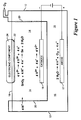
- FIGURE 1 is a schematic, cross-sectional view of a reducing agent regeneration system of the present invention as used in an exemplary process of restoring solderability of electronic components.
- the present invention comprises a method and apparatus for regenerating reducing agents used in chemical or electrochemical processes such as synthesis of organic compounds or restoring solderability of electronic components.
- the system of the present invention is described below in conjunction with a method of restoring the solderability of electronic components, such as printed wiring boards.
- the electrochemical system of the invention includes an anode and a cathode in aqueous electrolyte solutions.
- the electrolytes are contained in a vessel having one compartment for the cathode and catholyte and a second compartment for the anode and anolyte.
- the catholyte comprises an electrolyte with a redox couple, such as ions of vanadium or chromium, for example, comprising a reduced member and an oxidized member.
- the anolyte comprises a supporting electrolyte without the redox couple.
- the supporting electrolytes for the catholyte and the anolyte may have different pH values and may involve different anions in some cases.
- the reducing agent which comprises the reduced member of the redox couple and which is used in the exemplary process to reduce detrimental metallic oxides on solderable portions of electronic components, is generated at the cathode by electrochemical reduction of the oxidized member of the redox couple in the catholyte.
- the reduction process would be reversed at the anode (to a large extent) so that regeneration of the reducing agent would be very inefficient.
- the anolyte and catholyte must be separated by a semipermeable ionic barrier that allows protons to migrate from the anolyte to the catholyte but effectively opposes diffusion and migration of reducing agent cations across the barrier from the catholyte to the anolyte. This is necessary to minimize loss of the reducing agent and to avoid the anodic formation of higher-valent species, such as hexavalent chromium, for example, that may be environmentally objectionable.
- the semipermeable ionic barrier is an important feature of the present invention.
- Porous separators are known and have been used in prior art electrochemical cells as "diffusion barriers.” Because the polarity of typical separated cells is switched periodically, as between charging and discharging a battery, for example, the semipermeable nature of porous separators has not been fully exploited in electrochemical cells.
- a porous separator having an applied voltage is very effective in preventing transport of cations in one direction and anions in the other, especially when the pores are so small that "dead areas" are avoided. Because migration is typically a fast process compared with diffusion, back diffusion against the direction of migration for a given type of ion is small.
- the reduced member of the redox couple provides electrons to reduce metallic oxides (such as stannic oxide, for example, indicated as SnO2 in Figure 1) present on the surface of solder coatings on electronic components.
- the reaction oxidizes the reduced member of the redox couple (e.g., V2+ to V3+) and consumes protons (H+) to convert metallic oxides (M x O y ) to metal (M) and water (H2O).
- the half-cell reactions and overall reaction for electroless reduction of stannic oxide by vanadium ions are as follows: At the cathode, the oxidized member of the redox couple is returned to its reduced state (e.g., V3+ to V2+). At the anode, water is broken down into oxygen (O2), which is vented from the system, and protons (H+) that migrate across the ionic barrier to replace those consumed in the metallic oxide reduction at the electronic component.
- O2 oxygen
- H+ protons
- the electrode half-cell reactions and overall reaction for the electrochemical regeneration of the reduced member (V2+) of the redox couple are as follows:
- the overall system reaction is the sum of the electroless metallic oxide reduction and the electrochemical regeneration reactions, summarized as follows:
- the overall system reaction in this example is conversion of stannic oxide (SnO2) to tin metal (Sn) and oxygen (O2), with no net chemical change in the composition of the regeneration system.
- the overall reactions for reduction of other metallic oxides (or hydroxides), such as SnO, PbO, and CuO, for example, are similar to those expressed above for SnO2.
- FIG. 1 A schematic representation of a preferred embodiment of the regeneration system of the present invention is illustrated in Figure 1, using metallic oxide reduction for restoration of solderability as an exemplary process.
- the system includes a vessel 12 having two compartments for holding electrolyte solutions, comprising a catholyte 14 and an anolyte 16, at a fluid level 18.
- a first compartment of vessel 12 contains the catholyte solution 14 and a cathode 15.
- a second compartment of vessel 12 contains the anolyte solution 16 and an anode 17.
- Catholyte 14 and anolyte 16 are separated by a semipermeable ionic barrier 20.
- Ionic barrier 20 which may comprise a microporous glass separator (such as the Vycor® brand glass known as "thirsty” glass, for example, which has an average pore diameter in the range of 5 to 10 nm), provides microchannels between catholyte 14 and anolyte 16 that are under the influence of an electric field when a voltage is applied between cathode 15 and anode 17.
- the electric field produced across semipermeable ionic barrier 20 causes migration (i.e., movement under an applied electric field) of protons from anolyte 16 to catholyte 14, but opposes diffusion (and migration) of cations from catholyte 14 to anolyte 16.
- catholyte 14 comprises an aqueous solution of vanadous sulfate (VSO4) reducing agent and sulfuric acid.
- VSO4 vanadous sulfate
- Chromous sulfate (CrSO4) may also be used as the reducing agent, but it is less desirable in the exemplary process of solderability restoration for the reasons explained below.
- the pH of catholyte 14 should be less than about 1.0 and the reducing agent concentration should be at least 0.1 M .
- the ions of vanadium (V2+/V3+) or chromium (Cr2+/Cr3+) provide a redox couple for the reduction of metallic oxides 22 on solderable portions of an electronic component 24, such as a printed wiring board, for example, in contact with catholyte 14.
- Anolyte 16 may be a solution of a salt, base, or acid, but it should be chosen to maintain chemical balance within the system and not produce undesirable or hazardous by-products. With vanadous sulfate and sulfuric acid as catholyte 14, a preferred anolyte 16 is a sulfuric acid solution. Sulfuric acid anolyte solution 16 produces only oxygen and protons (H+) at anode 17. Protons (H+) migrate across semipermeable ionic barrier 20 to replenish protons consumed during reduction of metallic oxides on component 24, while the oxygen may be vented from the anolyte compartment, as illustrated in Figure 1.
- anions may migrate across ionic barrier 20 from catholyte 14 to anolyte 16, thereby increasing the acidity of anolyte 16 and decreasing the acidity of catholyte 14.
- Such anion migration can be minimized by operating the system with excess anolyte acidity.
- the acidity balance between catholyte 14 and anolyte 16 can be maintained by transferring a portion of anolyte 16 into catholyte 14 as needed. This may be accomplished, for example, by maintaining the fluid level of anolyte 16 above that of catholyte 14 so that there is a pressure differential causing anolyte 16 to flow slowly into catholyte 14 through ionic barrier 20.
- Excess water can be removed from catholyte 14 by evaporation using inert gas bubbling, for example, which also provides a blanket of inert gas to prevent oxidation of the reducing agent by oxygen from the atmosphere.
- An alternative method for removing excess water from catholyte 14 is reverse-osmosis, which is commonly used for water desalination. Water lost from anolyte 16 can be readily replenished.
- Anode 17 may comprise any inert material that is electrically conducting, but preferably a good oxygen evolution catalyst, such as platinized titanium or titanium-ruthenium oxide, for example.
- ions of chromium may also be used as the redox couple, but chromium has some undesirable attributes when used in the exemplary process of restoring solderability.
- chromium sulfate is used in catholyte 14
- residues that increase solder wetting time may be left on the surface of component 24.
- the increased wetting time which has been observed for Sn-Pb surfaces, may be caused by strong adsorption of chromium species and the possible formation of adsorbed Cr3+ oxide.
- chromium apparently forms a negatively charged complex with sulfate so that it is also transported into the anolyte during initial charging of the cell when sulfate is the primary current carrier across ionic barrier 20.
- the Cr2+/Cr3+ couple has a more negative redox potential than V2+/V3+, indicating that Cr2+ is more reducing than V2+ and may have advantages for use in some processes.
- ions of europium (Eu2+/Eu3+) may also be used as the redox couple.
- the redox potential of the Eu2+/Eu3+ couple lies between those of the V2+/V3+ and Cr2+/Cr3+ couples.
- Anions other than sulfate may also be used in the reducing agent regeneration system of the present invention.
- some anions such as fluoride nitrate, oxalate, and cyanide, for example
- fluoride nitrate, oxalate, and cyanide are unstable in acid solution and/or in the presence of highly reducing M2+ ions (such as V2+ and Cr2+, for example) and therefore are less desirable for most applications.
- Chloride anions are also considered undesirable because they would be oxidized to poisonous chlorine gas if present in the anolyte.
- electrochemically stable anions that may be useful in systems involving reducing agent regeneration include tetrafluoroborate, trifluoromethanesulfonate, and perchlorate (which is stable in the presence of Cr2+ and Eu2+, but not V2+).
- the material of cathode 15 should have a high hydrogen overvoltage (e.g., mercury, lead, indium, antimony, tantalum, bismuth, arsenic, carbon, cadmium, thallium, tin, or alloys thereof) so that most of the current goes to regenerating the reducing agent rather than discharging protons to hydrogen gas.
- Mercury is less desirable because it has limited surface area (i.e., inefficient for reducing agent regeneration), is hazardous to handle (i.e., liquid and toxic), and can dissolve in the electrolyte under some conditions.
- a preferred cathode material is lead (Pb) or a lead alloy, particularly for a system comprising a sulfate anion in catholyte 14.
- Lead has one of the highest hydrogen overvoltages of the common metals, is easy to handle, and is readily available in a form having a high surface area. In addition, lead forms an insoluble sulfate which prevents dissolution in sulfate-containing electrolytes when the redox couple is discharged (e.g., during shutdown or storage of the regeneration system).
- An alternative cathode material is carbon, which has a very high hydrogen overvoltage and is not subject to dissolution in aqueous electrolytes.
- the preferred system for practicing the present invention comprises a lead or lead alloy cathode 15, a vanadous sulfate (VSO4) and sulfuric acid catholyte 14 (having a pH of less than 1.0 and a VSO4 concentration of at least 0.1 M , and a sulfuric acid anolyte 16.
- VSO4 vanadous sulfate
- sulfuric acid catholyte 14 having a pH of less than 1.0 and a VSO4 concentration of at least 0.1 M
- sulfuric acid anolyte 16 The sulfate ion is very stable and prevents dissolution of lead or lead alloy cathode 15 by forming an insoluble sulfate on cathode 15.
- vanadium sulfate residues left on Sn-Pb coated components 24 treated to reduce surface oxides do not significantly affect solderability of the Sn-Pb coated components 24.
- vanadium ions (unlike those of chromium) apparently do not form negatively-charged complexes with sulfate. This is based on the observation that very little vanadium is transported from catholyte 14 to anolyte 16 during reduction of the vanadyl species (VO2+), which involves migration of sulfate anions from catholyte 14 to anolyte 16. Based on atomic absorption (AA) analysis of the anolyte for vanadium after a cell has been fully charged beginning with the vanadyl species (VO2+), vanadium ion migration accounts for less than one part in ten thousand of the total charge passed.
- AA atomic absorption
- the method of the present invention for regenerating reducing agents can also be used to initially produce reducing agents.
- the half-cell electrode reactions and overall reaction for reduction of vanadyl to vanadic species may be expressed as:
- acid is consumed at the cathode, thus causing an increase in pH. This effect must be taken into account for continuous operation of the overall system.
- lead or lead alloy cathode 15, microporous glass barrier 20, and vanadium sulfate and sulfuric acid catholyte 14 have important advantages for use in the exemplary system for restoring solderability.
- the combination of a lead or lead alloy cathode 15 and sulfate-containing catholyte 14 provides cathode stability under variable conditions and solution stability under the acidic conditions needed for metallic oxide reduction.
- the stability of sulfate ion against anodic oxidation permits water electrolysis to be the anodic reaction so that protons are generated to replace those used in metallic oxide reduction. Only oxygen is generated as a by-product.
- Microporous glass barrier 20 ensures that metal cations from catholyte 14 are effectively prevented from entering anolyte 16 so that there are no significant anodic side reactions that would disturb the chemical balance in the system.
- the combination of vanadium and sulfate provides efficient regeneration and fast metallic oxide discharge rates, avoids transport of cations to the anolyte, and circumvents strong adsorption on the solderable surface of species that degrade solderability.
Landscapes
- Chemical & Material Sciences (AREA)
- Engineering & Computer Science (AREA)
- Mechanical Engineering (AREA)
- Chemical Kinetics & Catalysis (AREA)
- Materials Engineering (AREA)
- Metallurgy (AREA)
- Organic Chemistry (AREA)
- General Chemical & Material Sciences (AREA)
- Electrochemistry (AREA)
- Electrolytic Production Of Metals (AREA)
- Electrolytic Production Of Non-Metals, Compounds, Apparatuses Therefor (AREA)
- Manufacture And Refinement Of Metals (AREA)
Applications Claiming Priority (2)
| Application Number | Priority Date | Filing Date | Title |
|---|---|---|---|
| US08/023,653 US5304297A (en) | 1993-02-26 | 1993-02-26 | Reducing agent regeneration system |
| US23653 | 1993-02-26 |
Publications (2)
| Publication Number | Publication Date |
|---|---|
| EP0612863A1 true EP0612863A1 (fr) | 1994-08-31 |
| EP0612863B1 EP0612863B1 (fr) | 1996-06-19 |
Family
ID=21816430
Family Applications (1)
| Application Number | Title | Priority Date | Filing Date |
|---|---|---|---|
| EP93110790A Expired - Lifetime EP0612863B1 (fr) | 1993-02-26 | 1993-07-06 | Procédé et appareil pour régénérer un agent réducteur |
Country Status (5)
| Country | Link |
|---|---|
| US (2) | US5304297A (fr) |
| EP (1) | EP0612863B1 (fr) |
| JP (1) | JPH07103472B2 (fr) |
| CA (1) | CA2098559C (fr) |
| DE (1) | DE69303266T2 (fr) |
Families Citing this family (12)
| Publication number | Priority date | Publication date | Assignee | Title |
|---|---|---|---|---|
| DE4344387C2 (de) * | 1993-12-24 | 1996-09-05 | Atotech Deutschland Gmbh | Verfahren zur elektrolytischen Abscheidung von Kupfer und Anordnung zur Durchführung des Verfahrens |
| US5466349A (en) * | 1995-01-06 | 1995-11-14 | Rockwell International Corporation | Potentiometric evaluation of substrate oxidation and coating porosity |
| US5605719A (en) * | 1995-03-03 | 1997-02-25 | Rockwell International Corporation | Method of transporting and applying a surface treatment liquid using gas bubbles |
| GB9515449D0 (en) * | 1995-07-27 | 1995-09-27 | Electrotech Equipments Ltd | Monitoring apparatus and methods |
| US5628893A (en) * | 1995-11-24 | 1997-05-13 | Atotech Usa, Inc. | Halogen tin composition and electrolytic plating process |
| US6315189B1 (en) * | 1998-10-13 | 2001-11-13 | Texas Instruments Incorporated | Semiconductor package lead plating method and apparatus |
| WO2002048430A2 (fr) * | 2000-09-27 | 2002-06-20 | Innovative Technology Licensing, Llc. | Composition, systeme et procede d'agent de reduction d'oxyde ameliore |
| US6776330B2 (en) * | 2001-09-10 | 2004-08-17 | Air Products And Chemicals, Inc. | Hydrogen fluxless soldering by electron attachment |
| US7079370B2 (en) * | 2003-04-28 | 2006-07-18 | Air Products And Chemicals, Inc. | Apparatus and method for removal of surface oxides via fluxless technique electron attachment and remote ion generation |
| DE102009060676B4 (de) * | 2009-12-28 | 2015-07-23 | Atotech Deutschland Gmbh | Verfahren und Vorrichtung zum nasschemischen Behandeln von Behandlungsgut |
| US10190227B2 (en) * | 2013-03-14 | 2019-01-29 | Xtalic Corporation | Articles comprising an electrodeposited aluminum alloys |
| US20170087379A1 (en) * | 2015-09-28 | 2017-03-30 | Filip Sedic | Light-activated acne treatment |
Citations (4)
| Publication number | Priority date | Publication date | Assignee | Title |
|---|---|---|---|---|
| EP0052509A2 (fr) * | 1980-11-17 | 1982-05-26 | Hitachi, Ltd. | Procédé pour enlever un oxyde sur une surface métallique |
| US4537666A (en) * | 1984-03-01 | 1985-08-27 | Westinghouse Electric Corp. | Decontamination using electrolysis |
| US5078842A (en) * | 1990-08-28 | 1992-01-07 | Electric Power Research Institute | Process for removing radioactive burden from spent nuclear reactor decontamination solutions using electrochemical ion exchange |
| US5104494A (en) * | 1991-07-02 | 1992-04-14 | Rockwell International Corp. | Method of restoring solderability |
Family Cites Families (1)
| Publication number | Priority date | Publication date | Assignee | Title |
|---|---|---|---|---|
| US5162082A (en) * | 1991-12-16 | 1992-11-10 | Electrovert Ltd. | Electrochemical reduction treatment for soldering |
-
1993
- 1993-02-26 US US08/023,653 patent/US5304297A/en not_active Expired - Lifetime
- 1993-06-16 CA CA002098559A patent/CA2098559C/fr not_active Expired - Fee Related
- 1993-06-30 JP JP5160580A patent/JPH07103472B2/ja not_active Expired - Fee Related
- 1993-07-06 EP EP93110790A patent/EP0612863B1/fr not_active Expired - Lifetime
- 1993-07-06 DE DE69303266T patent/DE69303266T2/de not_active Expired - Fee Related
- 1993-08-19 US US08/109,136 patent/US5411645A/en not_active Expired - Lifetime
Patent Citations (5)
| Publication number | Priority date | Publication date | Assignee | Title |
|---|---|---|---|---|
| EP0052509A2 (fr) * | 1980-11-17 | 1982-05-26 | Hitachi, Ltd. | Procédé pour enlever un oxyde sur une surface métallique |
| US4537666A (en) * | 1984-03-01 | 1985-08-27 | Westinghouse Electric Corp. | Decontamination using electrolysis |
| EP0154832A2 (fr) * | 1984-03-01 | 1985-09-18 | Westinghouse Electric Corporation | Décontamination par électrolyse |
| US5078842A (en) * | 1990-08-28 | 1992-01-07 | Electric Power Research Institute | Process for removing radioactive burden from spent nuclear reactor decontamination solutions using electrochemical ion exchange |
| US5104494A (en) * | 1991-07-02 | 1992-04-14 | Rockwell International Corp. | Method of restoring solderability |
Also Published As
| Publication number | Publication date |
|---|---|
| DE69303266T2 (de) | 1996-12-12 |
| US5411645A (en) | 1995-05-02 |
| EP0612863B1 (fr) | 1996-06-19 |
| JPH06248486A (ja) | 1994-09-06 |
| US5304297A (en) | 1994-04-19 |
| CA2098559C (fr) | 1998-11-17 |
| JPH07103472B2 (ja) | 1995-11-08 |
| CA2098559A1 (fr) | 1994-08-27 |
| DE69303266D1 (de) | 1996-07-25 |
Similar Documents
| Publication | Publication Date | Title |
|---|---|---|
| US5264097A (en) | Electrodialytic conversion of complexes and salts of metal cations | |
| US5304297A (en) | Reducing agent regeneration system | |
| US4118295A (en) | Regeneration of plastic etchants | |
| US5516972A (en) | Mediated electrochemical oxidation of organic wastes without electrode separators | |
| US20080302655A1 (en) | Electrochemical Method and Apparatus For Removing Oxygen From a Compound or Metal | |
| Lanza et al. | Removal of Zn (II) from chloride medium using a porous electrode: current penetration within the cathode | |
| US5258109A (en) | Electrodialytic conversion of complexes and salts of metal cations | |
| EP2877613B1 (fr) | Procédé d'extraction électrolytique réductrice sélective | |
| DE2850542C2 (de) | Verfahren zum Ätzen von Oberflächen aus Kupfer oder Kupferlegierungen | |
| JP2002322593A (ja) | 電解リン酸塩化成処理方法 | |
| EP0640424B1 (fr) | Ensemble de brasage en atmosphère réductrice, contenant de l'hydrogène | |
| US4652351A (en) | Electrochemical restoration of cyanide solutions | |
| Pruksathorn et al. | Lead recovery from waste frit glass residue of electronic plant by chemical-electrochemical methods | |
| MacLeod et al. | Electrochemistry of copper in aqueous acetonitrile | |
| US6984300B2 (en) | Method for recovering useful components from electrolytic phosphate chemical treatment bath | |
| DE3522714A1 (de) | Verfahren zur chemischen reaktivierung einer redoxzelle | |
| KR101136904B1 (ko) | 액체금속 전극을 이용한 금속 분리?정제 장치 및 방법 | |
| Maja et al. | Dissolution of pastes in lead-acid battery recycling plants | |
| DE3333650C2 (de) | Elektrochemische Redoxzelle | |
| US20220275527A1 (en) | Metal Recovery From Lead Containing Electrolytes | |
| Expósito et al. | Use of a hydrogen‐diffusion electrode in the electrochemical removal of lead from effluents of lead electrowinning processes | |
| DE19850524C2 (de) | Nitratfreies Recycling-Beizverfahren für Edelstähle | |
| DE19646945A1 (de) | Verfahren und Vorrichtung zur Aufarbeitung oder Regenerierung von Ätzbädern | |
| EP0283785A1 (fr) | Procédé pour la récupération du mercure par électrolyse | |
| JPH02159399A (ja) | 電解処理方法および電解処理装置 |
Legal Events
| Date | Code | Title | Description |
|---|---|---|---|
| PUAI | Public reference made under article 153(3) epc to a published international application that has entered the european phase |
Free format text: ORIGINAL CODE: 0009012 |
|
| AK | Designated contracting states |
Kind code of ref document: A1 Designated state(s): DE FR GB |
|
| 17P | Request for examination filed |
Effective date: 19941017 |
|
| 17Q | First examination report despatched |
Effective date: 19941121 |
|
| GRAH | Despatch of communication of intention to grant a patent |
Free format text: ORIGINAL CODE: EPIDOS IGRA |
|
| GRAA | (expected) grant |
Free format text: ORIGINAL CODE: 0009210 |
|
| AK | Designated contracting states |
Kind code of ref document: B1 Designated state(s): DE FR GB |
|
| REF | Corresponds to: |
Ref document number: 69303266 Country of ref document: DE Date of ref document: 19960725 |
|
| ET | Fr: translation filed | ||
| PLBE | No opposition filed within time limit |
Free format text: ORIGINAL CODE: 0009261 |
|
| STAA | Information on the status of an ep patent application or granted ep patent |
Free format text: STATUS: NO OPPOSITION FILED WITHIN TIME LIMIT |
|
| 26N | No opposition filed | ||
| REG | Reference to a national code |
Ref country code: GB Ref legal event code: IF02 |
|
| PGFP | Annual fee paid to national office [announced via postgrant information from national office to epo] |
Ref country code: FR Payment date: 20040720 Year of fee payment: 12 |
|
| PGFP | Annual fee paid to national office [announced via postgrant information from national office to epo] |
Ref country code: DE Payment date: 20040831 Year of fee payment: 12 |
|
| PGFP | Annual fee paid to national office [announced via postgrant information from national office to epo] |
Ref country code: GB Payment date: 20050629 Year of fee payment: 13 |
|
| PG25 | Lapsed in a contracting state [announced via postgrant information from national office to epo] |
Ref country code: DE Free format text: LAPSE BECAUSE OF NON-PAYMENT OF DUE FEES Effective date: 20060201 |
|
| PG25 | Lapsed in a contracting state [announced via postgrant information from national office to epo] |
Ref country code: FR Free format text: LAPSE BECAUSE OF NON-PAYMENT OF DUE FEES Effective date: 20060331 |
|
| REG | Reference to a national code |
Ref country code: FR Ref legal event code: ST Effective date: 20060331 |
|
| PG25 | Lapsed in a contracting state [announced via postgrant information from national office to epo] |
Ref country code: GB Free format text: LAPSE BECAUSE OF NON-PAYMENT OF DUE FEES Effective date: 20060706 |
|
| GBPC | Gb: european patent ceased through non-payment of renewal fee |
Effective date: 20060706 |