EP0612043B1 - Sheet Discriminating apparatus - Google Patents
Sheet Discriminating apparatus Download PDFInfo
- Publication number
- EP0612043B1 EP0612043B1 EP94102073A EP94102073A EP0612043B1 EP 0612043 B1 EP0612043 B1 EP 0612043B1 EP 94102073 A EP94102073 A EP 94102073A EP 94102073 A EP94102073 A EP 94102073A EP 0612043 B1 EP0612043 B1 EP 0612043B1
- Authority
- EP
- European Patent Office
- Prior art keywords
- sheet
- light receiving
- length
- screened
- circuit
- Prior art date
- Legal status (The legal status is an assumption and is not a legal conclusion. Google has not performed a legal analysis and makes no representation as to the accuracy of the status listed.)
- Expired - Lifetime
Links
- 230000004044 response Effects 0.000 claims description 6
- 230000001105 regulatory effect Effects 0.000 description 6
- 239000000428 dust Substances 0.000 description 4
- 230000006870 function Effects 0.000 description 4
- 238000010586 diagram Methods 0.000 description 3
- NIXOWILDQLNWCW-UHFFFAOYSA-N acrylic acid group Chemical group C(C=C)(=O)O NIXOWILDQLNWCW-UHFFFAOYSA-N 0.000 description 2
- 230000003321 amplification Effects 0.000 description 2
- 230000001276 controlling effect Effects 0.000 description 2
- 239000011521 glass Substances 0.000 description 2
- 238000003199 nucleic acid amplification method Methods 0.000 description 2
- 238000001514 detection method Methods 0.000 description 1
- 238000002845 discoloration Methods 0.000 description 1
- 230000000694 effects Effects 0.000 description 1
- 239000002783 friction material Substances 0.000 description 1
- 239000000463 material Substances 0.000 description 1
- 238000000034 method Methods 0.000 description 1
- 238000012986 modification Methods 0.000 description 1
- 230000004048 modification Effects 0.000 description 1
- 230000035945 sensitivity Effects 0.000 description 1
- 238000010200 validation analysis Methods 0.000 description 1
Images


Classifications
-
- G—PHYSICS
- G07—CHECKING-DEVICES
- G07D—HANDLING OF COINS OR VALUABLE PAPERS, e.g. TESTING, SORTING BY DENOMINATIONS, COUNTING, DISPENSING, CHANGING OR DEPOSITING
- G07D7/00—Testing specially adapted to determine the identity or genuineness of valuable papers or for segregating those which are unacceptable, e.g. banknotes that are alien to a currency
- G07D7/06—Testing specially adapted to determine the identity or genuineness of valuable papers or for segregating those which are unacceptable, e.g. banknotes that are alien to a currency using wave or particle radiation
- G07D7/12—Visible light, infrared or ultraviolet radiation
- G07D7/121—Apparatus characterised by sensor details
-
- G—PHYSICS
- G07—CHECKING-DEVICES
- G07D—HANDLING OF COINS OR VALUABLE PAPERS, e.g. TESTING, SORTING BY DENOMINATIONS, COUNTING, DISPENSING, CHANGING OR DEPOSITING
- G07D7/00—Testing specially adapted to determine the identity or genuineness of valuable papers or for segregating those which are unacceptable, e.g. banknotes that are alien to a currency
- G07D7/16—Testing the dimensions
- G07D7/162—Length or width
-
- G—PHYSICS
- G07—CHECKING-DEVICES
- G07D—HANDLING OF COINS OR VALUABLE PAPERS, e.g. TESTING, SORTING BY DENOMINATIONS, COUNTING, DISPENSING, CHANGING OR DEPOSITING
- G07D7/00—Testing specially adapted to determine the identity or genuineness of valuable papers or for segregating those which are unacceptable, e.g. banknotes that are alien to a currency
- G07D7/20—Testing patterns thereon
Definitions
- the present invention relates to a sheet discriminating apparatus to be installed in a sheet counting machine or the like for discriminating sheets such as bills or bank notes (hereinafter referred to collectively as "bills”) by kind.
- a sheet discriminating apparatus to be installed in a sheet counting machine or the like for discriminating sheets such as bills or bank notes (hereinafter referred to collectively as "bills") by kind.
- Japanese Utility Model Application laid open No. 63-80682 discloses a sheet discriminating apparatus using a CCD line sensor as light receiving elements arranged in the direction perpendicular to the sheet conveyance direction.
- the outputs of the line sensor are digitized for storage in a memory as image data. After the storage of the image data for the number of lines necessary for discriminating the kind of sheet, but before discrimination by use of pattern matching, the kind of sheet is preliminarily determined by detecting its length in the direction perpendicular to the conveyance direction.
- a characterizing area having a distinctive characteristic suitable for discriminating the kind of sheet is determined beforehand for each kind of sheet, and the Position of the characterizing area in the sheet is stored in the memory for each kind of sheet.
- the pattern corresponding to the characterizing area is also stored in the memory as reference pattern data for each kind of sheet.
- Document WO 92/17857 discloses a currency note width detector which enables the determination of the width of the traveling notes or documents by means of groups of LEDs which are disposed along a line extending perpendicular to the path of the doument travel. Validation of a currency note is performed by means of strip photodiodes which are disposed on the opposite sides of the path of a travelling document and which receive the light emitted by LEDs. The LEDs are sequentially energized one by one in order to determine the position of LEDs which are partially blocked by the currency note or sheet to be validated. A final determination of the sheet width is performed by counting the completely unblocked energized LEDs and the percent blocked of the partially blocked LED.
- the cost can be reduced by using the conventional photodiodes as the light receiving elements.
- photodiodes it is not possible to obtain the short intervals between adjacent light emitting elements and between adjacent light receiving elements that are necessary for accurately detecting the length of the sheet.
- the light emitted from a given light emitting element may be received by light receiving elements other than the associated light receiving element. Consequently, such an apparatus can not accurately detect the length of the sheet or the pattern thereof.
- a sheet discriminating apparatus for discriminating sheets by kind comprising a plurality of light emitting elements arranged in a plurality of lines in the direction perpendicular to a sheet conveyance direction, a plurality of light receiving elements each positioned to face an associated one of said light emitting elements, each of said light receiving elements receiving light emitted from the associated light emitting element, said light receiving elements being arranged such that at least one light receiving element receives light emitted from said associated light emitting element and is partially screened by the side edge of the conveyed sheet, a sheet length detecting means for detecting the length of the sheet in the direction perpendicular to said conveyance direction based upon the ratio of the outputs of the light receiving elements which are completely screened by the conveyed sheet to those of other light receiving elements which are partially screened by said conveyed sheet, and a pattern comparing means for determining pattern data of said sheet in accordance with time series outputs of said light receiving elements and for comparing said pattern data with a
- said sheet length detecting means is arranged so as to detect the lengths of the portions of the light receiving means which are partially screened by said conveyed sheet in accordance with said ratios of the outputs of the light receiving elements which are completely screened by the conveyed sheet to those of said light receiving elements which are partially screened by said conveyed sheet, and to detect the length of said sheet in the direction perpendicular to said conveyance direction in accordance with the lengths of said light receiving elements which are completely screened by said conveyed sheet and said the lengths of the portions.
- said sheet length detecting means includes first circuits arranged such that each first circuit outputs substantially 0 (zero) level when the associated light receiving element is completely screened by said conveyed sheet, and that it outputs a signal in accordance with the length of the portion of the associated light receiving element which is partially screened when the associated light receiving element is partially screened by the conveyed sheet, and a first processing means which can calculate the length of the light receiving elements which are partially screened by the conveyed sheet and the length of the light receiving elements which are completely screened by said conveyed sheet.
- said sheet discriminating apparatus further comprises a multiplexer means having a plurality of inputs and a single output for selectively outputting signals from said light receiving elements to said sheet length detecting means, wherein said sheet length detecting means includes a first circuit arranged such that the first circuit outputs substantially 0 (zero) level when the associated light receiving element is completely screened by said conveyed sheet, and that it outputs a signal in accordance with the length of the portion of the associated light receiving element which is partially screened when the associated light receiving element is partially screened by the conveyed sheet, and a first processing means which can calculate the length of the light receiving elements which are partially screened by the conveyed sheet and the length of the light receiving elements which are completely screened by said conveyed sheet.
- said pattern comparing means includes second circuits arranged such that each second circuit outputs a signal in response to minute variations in the output of the associated light receiving element when said light receiving element is completely screened, and a second processing means for discriminating the pattern of said sheet by comparing the outputs of said second circuits with said reference pattern data.
- each of said second circuits is connected to one of said first circuits to amplify the output of said first circuit to a predetermined level.
- said pattern comparing means includes a second circuit arranged such that the second circuit outputs a signal in response to minute variations in the output of the associated light receiving element when said light receiving element is completely screened, and a second processing means for discriminating the pattern of said sheet by comparing the outputs of said second circuits with said reference pattern data.
- said second circuit is connected to said first circuit to amplify the output of said first circuit to a predetermined level.
- said sheet discriminating apparatus further comprises a multiplexer means having a plurality of inputs and a single output for selectively outputting signals to said pattern comparing means, wherein said pattern comparing means includes a second circuit arranged such that the second circuit outputs a signal in response to minute variations in the output of the associated light receiving element when said light receiving element is completely screened, and a second processing means for discriminating the pattern of said sheet by comparing the output of said second circuit with said reference pattern data.
- said multiplexer means is connected to said first circuits and said second circuit is arranged to amplify the outputs of said first circuits via said multiplexer means to a predetermined level.
- said plurality of light emitting elements are arranged in two lines and said plurality of light receiving elements are arranged in two lines such that when viewed in the sheet conveyance direction no space not covered by the light receiving element is observed in the direction perpendicular to the sheet conveyance direction.
- said pattern comparing means is adapted to select the reference pattern data in accordance with the length of said sheet detected by said length detecting means.
- said reference pattern data comprises pattern data of a characterizing area of the sheet which the kind of sheet can be discriminated
- said pattern comparing means is adapted to preliminarily discriminate the kind of sheet in accordance with the length of the sheet detected by said length detecting means, to select the reference pattern data corresponding to said kind of sheet, and to compare the pattern data of the characterizing area of the sheet with said selected reference pattern data to conduct a final discrimination of the kind of sheet.
- Figure 1 is a schematic cross sectional view of a sheet discriminating apparatus which is an embodiment of the present invention.
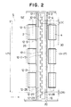
- Figure 2 is a schematic cross sectional view taken along line X-X in Figure 1.
- Figure 3 is a schematic enlarged partial view of a light receiving sensor section of Figure 2.
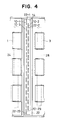
- Figure 4 is a schematic cross sectional view taken along line Y-Y in Figure 1.
- Figure 5 is a block diagram of a control circuit of a sheet discriminating apparatus which is an embodiment of the present invention.
- Figures 6A, 6B and 6C are graphs showing time series variation of output voltages of a first circuit.
- Figure 7 is a schematic enlarged partial view of light receiving sensors where two light receiving sensors on different lines are screened by the side edge of the sheet.
- Figure 8 is a schematic view for describing the detection of the length of a sheet when the sheet is undesirably transported.
- Figures 9A and 9B are graphs showing time series variations of output voltages of a second circuit.
- Figure 10 is a block diagram of a control circuit of a sheet discriminating apparatus which is another embodiment of the present invention.
- a sheet discriminating apparatus for discriminating sheets S comprises two pairs of conveyance rollers 1, 2 and 3, 4 for conveying sheets S in the conveyance direction C, a light emitting section 10 which emits light onto the surface of conveyed sheets S, a light receiving sensor section 12 positioned above the light emitting section 10 for receiving light emitted from the light emitting section 10 and transmitted through the sheets S, a filter 14 for preventing dust or the like from attaching to the light emitting section 10, a filter 16 for ensuring that only the light from directly opposite the light receiving sensor section 12 can be transmitted therethrough and for preventing dust or the like from attaching to the light receiving sensor section 12, a base board 18 for supporting the light receiving sensor section 12, a holder 20 for supporting the filter 16 and the base board 18, and a holder 22 for supporting the light emitting section 10 and the filter 14.
- the two pairs of conveyance rollers 1, 2 and 3, 4 are made by baking a high friction material such as rubber around shafts 24, 26 and 28, 30, respectively.
- the members of each pair of conveyance rollers 1, 2 and the pair of transporting rollers 3, 4 are pressed against each other.
- the conveyance rollers 1, 3 are drive rollers and the rollers 2, 4 are driven rollers.
- the conveyance rollers 1, 3 are rotated clockwise by driving means (not shown) at the same rate.
- driving means not shown
- the conveyance rollers 2, 4 are rotated counterclockwise.
- a rotary encoder (not shown) is mounted on the shaft 26 to detect the number of rotation of the shaft 26.
- the light receiving sensor section 12 is mounted on the base board 18, which is mounted on the holder 20.
- the filter 16 is made of a transparent glass or acrylic plate and is mounted on the holder 20 at a distance from the light receiving sensor section 12. The filter 16 prevents dust or the like from attaching to the light receiving sensor section 12.
- the filter 14 is made of a transparent glass or acrylic plate, and is mounted on the surface of the holder 22 to prevent dust or the like form attaching to the light emitting section 10.
- Figure 2 is a schematic cross sectional view taken along line X-X in Figure 1
- Figure 3 is a schematic enlarged partial view of the light receiving sensor section 12.
- the light receiving sensor section 12 comprises twenty-nine light receiving sensors 12-1 to 12-29.
- the light receiving sensors 12-i (wherein integer “i" equals 1 to 29), each of which has a rectangular lateral cross section, are staggered in two lines.
- Each light receiving sensor 12-i is constituted as a photoelectric device such as a photodiode which converts received light into a voltage proportional to the light intensity.
- each of the light receiving sensors 12-i has a length L(A), e.g. 1.6 mm, in the conveyance direction C and a length L(B), e.g.
- Adjacent light receiving sensors are disposed at an interval P(A), e.g. 3.5 mm, in the conveyance direction C and at an interval P(B), e.g. 6 mm, in the direction perpendicular to the conveyance direction C.
- the portions of the filter 16 mounted on the holder 20 other than those which face the light receiving sensors 12-1 to 12-29 are printed with a silkscreen or applied with a seal overlay. Therefore, the light transmitted through the sheet S can be transmitted only through the portions facing the light receiving sensors 12-1 to 12-29.
- the light emitting section 10 is arranged to face the light receiving sensor section 12.
- Figure 4 is a schematic cross sectional view taken along line Y-Y in Figure 1.
- the light emitting section 10 comprises twenty-nine light emitting elements 10-1 to 10-29.
- the light emitting elements 10-i (wherein integer “i" equals 1 to 29), each of which has a rectangular lateral cross section, are staggered in two lines such that each of the light emitting elements 10-i faces an associated one of the light receiving sensor elements 12-i and the light emitting elements 10-i and the light receiving sensor elements 12-i are positioned symmetrically with respect to the filters 14, 16.
- the amount of light emitted from each light emitting element 10-i can be independently adjusted.
- each of the light emitting elements 10-i emits light having a large half-width. Since the light emitted from a light emitting element does not consist of parallel rays but generally has a certain half-width, even in a single light receiving sensor, the received light intensity may differ between different areas thereof (e.g., between the central portion of the light receiving sensor and the end portion thereof). Accordingly, in this embodiment, light emitting elements which emit light having as large a half-width as possible are used in order to make the density of light received by a single light receiving sensor uniform so as to uniformly project light onto the whole area of the light receiving sensor 12-i.
- the distance between the light emitting section 10 and the light receiving sensor section 12 is determined depending upon the light intensity, it is preferable to set it as long as practicable for uniformly projecting light onto each of the light receiving sensors 12-i.
- the distance between the light emitting section 10 and the light receiving sensor section 12 is set to be 30 mm.
- apertures 22-1 to 22-29 are formed on the portions of the surface of the holder 22 facing the light receiving sensors 12-1 to 12-29 and the light receiving sensors 12-1 to 12-29 are staggered in two lines. Consequently, even though a light emitting element 10-i emits light of a large half-width, it is ensured that the light emitting from the light emitting element 10-i is received only by the associated light receiving sensor 12-i.
- FIG. 5 is a block diagram of a control circuit for the light receiving sensor 12-i of the sheet discriminating apparatus.
- the control circuit includes a first circuit 40, a second circuit 50, analog-digital converters (hereinafter referred to as "A/D converters") 60, 65, a central processing unit (hereinafter referred to as "CPU”) 70, a digital-analog converter (hereinafter referred to as "D/A converter”) 80, and a received light level regulating circuit 90.
- Each light receiving sensor 12-i is connected to the first circuit 40, which is connected to the second circuit 50 and is also connected to the A/D converter 60.
- the A/D converter 60 is connected to a first terminal T1 of the CPU 70.
- the second circuit 50 is connected to the A/D converter 65, which is connected to a second terminal T2 of the CPU 70.
- the received light level regulating circuit 90 is adapted for controlling the driving current for the light emitting element 10-i and is connected to the D/A converter 80 which is connected to the CPU 70.
- a processing unit consisting of a first circuit 40, a second circuit 50, A/D converters 60, 65, a D/A converter 80 and a received light regulating circuit 90 is provided for each pair of the light emitting elements 10-i and light receiving sensors 12-i, whereas the CPU 70 is common to all units.
- the first circuit 40 When a light receiving sensor 12-i receives the light emitted from the associated light emitting element 10-i, it outputs a signal to the first circuit 40.
- the first circuit 40 includes an amplifier Am1 and resistors R1, R2 each having a prescribed resistance value, and has a small amplification factor.
- the first circuit 40 is adjusted to output a reference voltage (e.g. 5 V) as a signal when the light receiving sensor 12-i receives the light emitted from the light emitting element 10-i without being screened by the sheet S, and to output a signal of substantially 0 (zero) level (e.g.
- the second circuit 50 includes an amplifier Am2 and resistors R3, R4 and R5 each having a prescribed resistance value and has a large amplification factor.
- the second circuit 50 is arranged to be able to detect minute variation in the voltage caused by the change in the amount of the light transmitted through the sheet and received by the light receiving sensor 12-i when the light receiving sensor 12-i receives substantially no light, namely, when the light receiving sensor 12-i is completely screened by the sheet S.
- the light receiving sensors 12-1, 12-2 and 12-29 are not screened by the sheet S.
- the output voltages of the first circuits 40 connected to the light receiving sensors 12-1, 12-2 and 12-29 are 5 V. These output voltages are constant at 5V, which is to say that the change in the output voltages is 0 (zero) V.
- the light receiving sensors 12-4 to 12-27 are screened by the sheet S when the sheet S passes thereabove.
- the output voltages of the first circuits 40 connected to the light receiving sensors 12-4 to 12-27 change as shown in Figure 6A. More specifically, the output voltages thereof are stay at 5 V until time t1 when the front edge of the sheet S reaches the position above the light receiving sensors 12-4 to 12-27. Then, they decrease by the reference voltage variation V(0) and stay at substantially 0 (zero) V until time t2 when the rear edge of the sheet S reaches the position above the light receiving sensors 12-4 to 12-27. After the sheet has passed through the position above the light receiving sensors 12-4 to 12-27, the output voltages of the first circuits 40 connected to the light receiving sensors 12-4 to 12-27 increases to 5 V.
- the light receiving sensors 12-3, 12-28 are partially screened by the sheet S when the sheet passes thereabove. Accordingly, the output voltages of the first circuits 40 connected to the light receiving sensors 12-3 and 12-28 change as shown in Figures 6B and 6C. More specifically, the output voltages stay at levels lower than 5 V from t1 to t2. However, the changes in the output voltages V(3) and V(28) are smaller than the reference voltage variation V(0).
- the output signal of each first circuit 40 is input to the first terminal T1 of the CPU 70 via the A/D converter 60.
- the CPU 70 calculates the length of the sheet S to preliminarily discriminate the kind of sheet in accordance with the input signals.
- the CPU 70 calculates the length L(3) of the portion of the light receiving sensor 12-3 screened by the sheet S in accordance with the following equation (1).
- L(3) L(B) • ⁇ V(3)/V(0) ⁇
- the CPU 70 calculates the length L(4-27) of the portion of the light receiving sensors 12-4 to 12-27 screened by the sheet S in accordance with the following equation (3) and then the whole length L(S) of the sheet S can be calculated in accordance with the following equation (4).
- L(4-27) P(B)•(27-4+1)- ⁇ L(B)-P(B) ⁇
- L(S) L(3)+L(28)+L(4-27)
- the whole length L(S) of the sheet S can be calculated based upon the length L(4) of the portion of the more inwardly positioned light receiving sensor 12-4 screened by the sheet S.
- the CPU 70 corrects the calculated length of the sheet as follows.
- the angle ⁇ of the side edge SE of the sheet S with respect to the conveyance direction C is calculated based upon the output signals of two light receiving sensors which are completely screened by the sheet S passing thereabove.
- the CPU 70 determines the time when the change in the output voltage of the first circuit 40 which receives the output signal the light receiving sensor 12-9 becomes (1/2)•V(0) and the time when the change in the output voltage of the first circuit 40 which receives the output signal from the light receiving sensor 12-21 becomes (1/2)•V(0).
- the CPU 70 calculates the length L'(S) of the sheet in the direction perpendicular to the conveyance direction C in accordance with the following equation (5).
- L'(S) L(3)+L(28)+L(4-27)+P(A) • tan( ⁇ ) wherein P(A) • tan( ⁇ ) is the deviation caused by the fact that the light receiving sensors 12-4 and 12-7 are positioned in different lines. Consequently, the CPU 70 calculates the actual length L(S) of the sheet S as shown in Figure 8B in accordance with the following equation (6).
- the CPU 70 calculates the length L(S) of the sheet S and, via the A/D converter 65 and the second terminal T2, receives the output signals from the second circuits 50 each connected to one of the light receiving sensors 12-1 to 12-29. After storing the received signals as pattern data in a random access memory (hereinafter referred to as "RAM") (not shown), the CPU 70 then preliminarily discriminates the kind of sheet based upon the length L(S) of the sheet S with reference to data stored in a read only memory (hereinafter referred to as "ROM”) (not shown), and reads the data on the characterizing area of the sheet preliminarily discriminated.
- RAM random access memory
- ROM read only memory
- the characterizing area is determined in advance as an area in the sheet suitable for discriminating the kind of sheet, and the position of the area in the sheet is stored in the ROM for each kind of sheet.
- the pattern data corresponding to the characterizing area are also stored as reference pattern data in the ROM for every kind of sheet.
- the CPU 70 reads from the RAM the pattern data of the sheet S corresponding to the characterizing area read from the ROM.
- the CPU 70 reads the reference pattern data of the kind of sheet preliminarily discriminated from among the reference pattern data stored in the ROM for each kind of sheet and effects pattern matching by comparing the reference pattern data with the pattern data of the sheet S read from the RAM so as to make a final discrimination of the kind of sheet.
- Figure 9A shows time series variations of the output voltage V of a second circuit 50 which is connected to a light receiving sensor positioned apart from the side edge SE of the sheet S at a predetermined distance.
- the curve V(a) shows the change in the output voltage V when a Japanese 10,000 yen bill is conveyed
- the curve V(b) shows the change when a Japanese 5,000 yen bill is conveyed.
- the pattern data of the sheet S are generated from the time series variations of the output voltages of the second circuits 50 each connected to one of the light receiving sensors, and are stored in the RAM.
- the CPU 70 feeds control signals to the respective received light level regulating circuits 90 via the associated D/A converters 70.
- Each of the received light level regulating circuits 90 controls the driving current for the associated light receiving sensor 12-i by controlling the base current of a transistor TR supplied from an amplifier Am3 such that each light receiving sensor 12-i associated with a the light emitting element 10-i outputs the same voltage under the same condition.
- the first circuit 40, the second circuit 50 and the A/D converters 60, 65 are provided separately for each of the light receiving sensors 12-i, it is possible to provide only a single first circuit 40, second circuit 50, A/D converter 60, and A/D converter 65 and to connect the first circuit 40 to a multiplexer 100 which is connected to the light receiving elements 12-i, as shown in Figure 10. In this case, the multiplexer 100 is driven by use of a time sharing method.
- the D/A converter 80 and the received light level regulating circuit 90 are provided separately for each of the light emitting elements 10-i, it is possible to use a multiplexer 110 and sample and hold circuits 120 to accomplish the same function as in the above described embodiment.
- each light emitting element 10-i and of each light receiving sensor 12-i shape and the size of each light emitting element 10-i and of each light receiving sensor 12-i, the distance between adjacent light emitting elements, and the distance between adjacent light receiving sensors are not limited to those in the above described embodiment. Similarly, the number of the light emitting elements and the light receiving sensors is not limited.
- the light emitting elements 10-1 to 10-29 and the light receiving sensors 12-1 to 12-29 are regularly arranged, this is not necessary and they need only be arranged such that at least one light receiving sensor 12-i is screened from the light emitted from the associated light emitting element 10-i by the side edge SE of the sheet S.
- the light emitting elements 10-1 to 10-29 and the light receiving sensors 12-1 to 12-29 are arranged in two lines, this is not necessary and they may be arranged in three or more lines insofar as at least one light receiving sensor 12-i is screened from the light emitted from the associated light emitting element 10-i with the side edge SE of the sheet S.
- the CPU 70 preliminarily discriminates the kind of sheet by calculating the length of the sheet S, reads the pattern data on a specific characterizing area of the sheet S in accordance with the result of the preliminary discrimination and the reference pattern data of the characterizing area for effecting pattern matching so as to make a final discrimination of the kind of sheet.
- the sheet discriminating apparatus may be designed to compare the pattern data of the sheet S with the reference pattern data independently from the preliminary discrimination of the kind of sheet in accordance with the length of the sheet S and to discriminate the kind of sheet in accordance with the result of both the comparison and the discrimination.
- the first circuit 40 is adjusted such that it outputs a reference voltage of 5 V as a signal when the associated light receiving sensor 12-i receives the light emitted from the light emitting element 10-i without being screened by the sheet S, and outputs a signal of substantially 0 (zero) V when the associated light receiving sensor 12-i receives substantially no light. Therefore, the reference voltage variation V(0) is substantially 5 V. However, since it is sufficient for the reference voltage variation V(0) to be constant for the material of the sheets to be discriminated, it is not necessary for the reference voltage variation V(0) to be 5 V or for the output signal to be substantially 0 (zero) V when the light receiving sensor 12-i receives substantially no light.
- the respective means need not necessarily be physical means and arrangements whereby the function of the respective means is accomplished by software fall within the scope of the appended claims.
- the function of a single means may be accomplished by two or more physical means and the functions of two or more means may be accomplished by a single physical means.
Landscapes
- Health & Medical Sciences (AREA)
- General Health & Medical Sciences (AREA)
- Toxicology (AREA)
- Physics & Mathematics (AREA)
- General Physics & Mathematics (AREA)
- Inspection Of Paper Currency And Valuable Securities (AREA)
- Length Measuring Devices By Optical Means (AREA)
- Controlling Sheets Or Webs (AREA)
Description
Claims (13)
- A sheet discriminating apparatus for discriminating sheets (S) by kind comprising:characterized in that,a plurality of light emitting elements (10-1 to 10-29),a plurality of light receiving elements (12-1 to 12-29),a sheet length detecting means (40, 60, 70) for detecting the length of the sheet (S) in the direction perpendicular to the conveyance direction (C),said plurality of light emitting elements (10-1 to 10-29) is arranged in a plurality of lines in the direction perpendicular to said sheet conveyance direction (C),each of said light receiving elements (12-i) is positioned to face an associated one of said light emitting elements (10-i), each of said light receiving elements (12-i) is receiving light emitted from the associated light emitting element (10-i), said light receiving elements (12-i) being arranged such that at least one light receiving element (12-i) receives light emitted from said associated light emitting element (10-i) and is partially screened by the side edge (SE) of the conveyed sheet (S),said sheet length detecting means (40, 60, 70) is detecting the length L(S) of the sheet (S) based upon the ratio of the outputs of the light receiving elements (12-4 to 12-27) which are completely screened by the conveyed sheet (S) to those of other light receiving elements (12-3, 12-28) which are partially screened by said conveyed sheet (S),a pattern comparing means (50, 65, 70) for determining pattern data of said sheet (S) in accordance with the time series outputs of said light receiving elements (12-1 to 12-29) and for comparing said pattern data with a reference pattern data selected from a plurality of reference pattern data each corresponding to a kind of sheet (S),said kind of sheet (S) being discriminated in accordance with the length of the sheet L(S) detected by said sheet length detecting means (40, 60, 70) and the result obtained by said pattern comparing means (50, 65, 70).
- A sheet discriminating apparatus according to claim 1, wherein said sheet length detecting means (40, 60, 70) is arranged so as to detect the lengths of the portions of the light receiving elements (12-3, 12-28) which are partially screened by said conveyed sheet (S) in accordance with said ratios of the outputs of the light receiving elements (12-4 to 12-27) which are completely screened by the conveyed sheet (S) to those of said light receiving elements (12-3, 12-28) which are partially screened by said conveyed sheet (S), and to detect the length of said sheet L(S) in the direction perpendicular to said conveyance direction (C) in accordance with the lengths of said light receiving elements (12-4 to 12-27) which are completely screened by said conveyed sheet (S) and said lengths of the portions.
- A sheet discriminating apparatus according to claim 1 or 2, wherein said sheet length detecting means (40, 60, 70) includes first circuits (40) arranged such that each first circuit (40) outputs substantially 0 (zero) level when the associated light receiving element is completely screened by said conveyed sheet (S), and that it outputs a signal in accordance with the length of the portion of the associated light receiving element which is partially screened when the associated light receiving element is partially screened by the conveyed sheet (S), and a first processing means (60, 70) which can calculate the length of the light receiving elements which are partially screened by the conveyed sheet (S) and the length of the light receiving elements which are completely screened by said conveyed sheet (S).
- A sheet discriminating apparatus according to claim 1 or 2, said sheet discriminating apparatus further comprising a multiplexer means (100) having a plurality of inputs and a single output for selctively outputting signals from said light receiving elements (12-i) to said sheet length detecting means (40, 60, 70), wherein said sheet length detecting means (40, 60, 70) includes a first circuit (40) arranged such that the first circuit (40) outputs substantially 0 (zero) level when the associated light receiving element is completely screened by said conveyed sheet (S), and that it outputs a signal in accordance with the length of the portion of the associated light receiving element which is partially screened when the associated light receiving element is partially screened by the conveyed sheet (S), and a first processing means (60, 70) which can calculate the length of the light receiving elements which are partially screened by the conveyed sheet (S) and the length of the light receiving elements which are completely screened by said conveyed sheet (S).
- A sheet descriminating apparatus according to claims 1 to 3, wherein said pattern comparing means (50, 65, 70) includes second circuits (50) arranged such that each second circuit (50) outputs a signal in response to minute variations in the output of the associated light receiving element (12-i) when said light receiving element is completely screened, and a second processing means (65, 70) for discriminating the pattern of said sheet (S) by comparing the outputs of said second circuits (50) with said reference pattern data.
- A sheet discriminating apparatus according to claim 5, wherein each of said second circuits (50) is connected to one of said first circuits (40) to amplify the output of said first circuit (40) to a predetermined level.
- A sheet discriminating apparatus according to claim 4, wherein said pattern comparing means (50, 65, 70) includes a second circuit (50) arranged such that the second circuit (50) outputs a signal in response to minute variations in the output of the associated light receiving element (12-i) when said light receiving element is completely screened, and a second processing means (65, 70) for discriminating the pattern of said sheet (S) by comparing the outputs of said second circuits (50) with said reference pattern data.
- A sheet discriminating apparatus according to claim 7, wherein said second circuit (50) is connected to said first circuit (40) to amplify the output of said first ciruit (40) to a predetermined level.
- A sheet discrimination apparatus according to claims 1 to 3, said sheet discriminating apparatus further comprising a multiplexer means (100) having a plurality of inputs and a single output for selectively outputting signals to said pattern comparing means, wherein said pattern comparing means (50, 65, 70) includes a second circuit (50) arranged such that the second circuit (50) outputs a signal in response to minute variations in the output of the associated light receiving element (12-i) when said light receiving element is completely screened, and a second processing means (65, 70) for discriminating the pattern of said sheet (S) by comparing the output of said second circuit (50) with said reference pattern data.
- A sheet discriminating apparatus according to claim 9, wherein said multiplexer means (100) is connected to said first circuits (40) and said second circuit (50) is arranged to amplify the outputs of said first circuits (40) via said multiplexer means (100) to a predetermined level.
is arranged to amplify the outputs of said first circuits (40) via said multiplexer means (100) to a predetermined level. - A sheet discriminating apparatus according to claims 1 to 10, wherein said plurality of light emitting elements (10-1 to 10-29) arranged in two lines and said plurality of light receiving elements (12-1 to 12-29) are arranged in two lines such that when viewed in the sheet conveyance direction ( C ) no space not covered by a light receiving element (12-i) is observed in the direction perpendicular to the sheet conveyance direction ( C ).
- A sheet discriminating apparatus according to claims 1 to 11, wherein said pattern comparing means (50, 65, 70) is adapted to select the reference pattern data in accordance with the length of said sheet L(S) detected by said length detecting means (40, 60, 70).
- A sheet discriminating apparatus according to claims 1 to 12, wherein said reference pattern data comprises pattern data of a characterizing area of the sheet (S) from which the kind of sheet can be discriminated, and said pattern comparing means (50, 65, 70) is adapted to preliminarily discriminate the kind of sheet in accordance with the length of the sheet L(S) detected by said length detecting means (40, 60, 70), to select the refernce pattern data corresponding to said kind of sheet (S), and to compare the pattern data of the characterizing area of the sheet (S) with said selected reference pattern data to conduct a final discrimination of the kind of sheet (S).
Applications Claiming Priority (2)
| Application Number | Priority Date | Filing Date | Title |
|---|---|---|---|
| JP5029121A JP2930494B2 (en) | 1993-02-18 | 1993-02-18 | Sheet discrimination device |
| JP29121/93 | 1993-02-18 |
Publications (3)
| Publication Number | Publication Date |
|---|---|
| EP0612043A2 EP0612043A2 (en) | 1994-08-24 |
| EP0612043A3 EP0612043A3 (en) | 1996-07-24 |
| EP0612043B1 true EP0612043B1 (en) | 1998-10-14 |
Family
ID=12267480
Family Applications (1)
| Application Number | Title | Priority Date | Filing Date |
|---|---|---|---|
| EP94102073A Expired - Lifetime EP0612043B1 (en) | 1993-02-18 | 1994-02-10 | Sheet Discriminating apparatus |
Country Status (5)
| Country | Link |
|---|---|
| US (1) | US5465821A (en) |
| EP (1) | EP0612043B1 (en) |
| JP (1) | JP2930494B2 (en) |
| KR (1) | KR0141513B1 (en) |
| DE (1) | DE69413865T2 (en) |
Families Citing this family (82)
| Publication number | Priority date | Publication date | Assignee | Title |
|---|---|---|---|---|
| US6241069B1 (en) | 1990-02-05 | 2001-06-05 | Cummins-Allison Corp. | Intelligent currency handling system |
| US6959800B1 (en) * | 1995-12-15 | 2005-11-01 | Cummins-Allison Corp. | Method for document processing |
| US5790693A (en) * | 1990-02-05 | 1998-08-04 | Cummins-Allison Corp. | Currency discriminator and authenticator |
| US6311819B1 (en) | 1996-05-29 | 2001-11-06 | Cummins-Allison Corp. | Method and apparatus for document processing |
| US5992601A (en) * | 1996-02-15 | 1999-11-30 | Cummins-Allison Corp. | Method and apparatus for document identification and authentication |
| US5966456A (en) | 1990-02-05 | 1999-10-12 | Cummins-Allison Corp. | Method and apparatus for discriminating and counting documents |
| US5960103A (en) * | 1990-02-05 | 1999-09-28 | Cummins-Allison Corp. | Method and apparatus for authenticating and discriminating currency |
| US5875259A (en) | 1990-02-05 | 1999-02-23 | Cummins-Allison Corp. | Method and apparatus for discriminating and counting documents |
| US6913130B1 (en) | 1996-02-15 | 2005-07-05 | Cummins-Allison Corp. | Method and apparatus for document processing |
| US5790697A (en) | 1990-02-05 | 1998-08-04 | Cummins-Allion Corp. | Method and apparatus for discriminating and counting documents |
| US5295196A (en) * | 1990-02-05 | 1994-03-15 | Cummins-Allison Corp. | Method and apparatus for currency discrimination and counting |
| US5652802A (en) * | 1990-02-05 | 1997-07-29 | Cummins-Allison Corp. | Method and apparatus for document identification |
| US6220419B1 (en) | 1994-03-08 | 2001-04-24 | Cummins-Allison | Method and apparatus for discriminating and counting documents |
| US6915893B2 (en) | 2001-04-18 | 2005-07-12 | Cummins-Alliston Corp. | Method and apparatus for discriminating and counting documents |
| US6628816B2 (en) | 1994-08-09 | 2003-09-30 | Cummins-Allison Corp. | Method and apparatus for discriminating and counting documents |
| ES2106672B1 (en) * | 1994-12-23 | 1998-06-01 | Azkoyen Ind Sa | METHOD AND APPARATUS FOR THE CHARACTERIZATION AND DISCRIMINATION OF TICKETS AND LEGAL COURSE DOCUMENTS. |
| US6748101B1 (en) | 1995-05-02 | 2004-06-08 | Cummins-Allison Corp. | Automatic currency processing system |
| US6363164B1 (en) | 1996-05-13 | 2002-03-26 | Cummins-Allison Corp. | Automated document processing system using full image scanning |
| US6880692B1 (en) * | 1995-12-15 | 2005-04-19 | Cummins-Allison Corp. | Method and apparatus for document processing |
| US6278795B1 (en) | 1995-12-15 | 2001-08-21 | Cummins-Allison Corp. | Multi-pocket currency discriminator |
| US6661910B2 (en) | 1997-04-14 | 2003-12-09 | Cummins-Allison Corp. | Network for transporting and processing images in real time |
| US8950566B2 (en) | 1996-05-13 | 2015-02-10 | Cummins Allison Corp. | Apparatus, system and method for coin exchange |
| US20050276458A1 (en) | 2004-05-25 | 2005-12-15 | Cummins-Allison Corp. | Automated document processing system and method using image scanning |
| US7187795B2 (en) | 2001-09-27 | 2007-03-06 | Cummins-Allison Corp. | Document processing system using full image scanning |
| US8162125B1 (en) | 1996-05-29 | 2012-04-24 | Cummins-Allison Corp. | Apparatus and system for imaging currency bills and financial documents and method for using the same |
| US6860375B2 (en) | 1996-05-29 | 2005-03-01 | Cummins-Allison Corporation | Multiple pocket currency bill processing device and method |
| US7903863B2 (en) | 2001-09-27 | 2011-03-08 | Cummins-Allison Corp. | Currency bill tracking system |
| US6026175A (en) * | 1996-09-27 | 2000-02-15 | Cummins-Allison Corp. | Currency discriminator and authenticator having the capability of having its sensing characteristics remotely altered |
| US8478020B1 (en) | 1996-11-27 | 2013-07-02 | Cummins-Allison Corp. | Apparatus and system for imaging currency bills and financial documents and method for using the same |
| AU7159098A (en) | 1997-05-07 | 1998-11-27 | Cummins-Allison Corp. | Intelligent currency handling system |
| US6039645A (en) | 1997-06-24 | 2000-03-21 | Cummins-Allison Corp. | Software loading system for a coin sorter |
| US5940623A (en) | 1997-08-01 | 1999-08-17 | Cummins-Allison Corp. | Software loading system for a coin wrapper |
| US5855268A (en) * | 1997-10-01 | 1999-01-05 | Mars Incorporated | Optical sensor system for a bill validator |
| US6318714B1 (en) * | 1997-11-28 | 2001-11-20 | Diebold, Incorporated | Document unstack system for currency recycling automated banking machine |
| US6493461B1 (en) | 1998-03-17 | 2002-12-10 | Cummins-Allison Corp. | Customizable international note counter |
| US6304660B1 (en) | 1998-05-29 | 2001-10-16 | Welch Allyn Data Collection, Inc. | Apparatuses for processing security documents |
| ATE242497T1 (en) * | 1999-01-14 | 2003-06-15 | Rue De Int Ltd | MONITORING SYSTEM |
| US6318537B1 (en) | 1999-04-28 | 2001-11-20 | Cummins-Allison Corp. | Currency processing machine with multiple internal coin receptacles |
| US6637576B1 (en) | 1999-04-28 | 2003-10-28 | Cummins-Allison Corp. | Currency processing machine with multiple internal coin receptacles |
| US6222623B1 (en) | 1999-09-03 | 2001-04-24 | Mars Incorporated | Integrating light mixer |
| US6398000B1 (en) | 2000-02-11 | 2002-06-04 | Cummins-Allison Corp. | Currency handling system having multiple output receptacles |
| US6588569B1 (en) | 2000-02-11 | 2003-07-08 | Cummins-Allison Corp. | Currency handling system having multiple output receptacles |
| US6601687B1 (en) | 2000-02-11 | 2003-08-05 | Cummins-Allison Corp. | Currency handling system having multiple output receptacles |
| US8701857B2 (en) | 2000-02-11 | 2014-04-22 | Cummins-Allison Corp. | System and method for processing currency bills and tickets |
| JP2001297349A (en) * | 2000-04-14 | 2001-10-26 | Sanden Corp | Paper money identifying device |
| JP2001344635A (en) * | 2000-06-02 | 2001-12-14 | Birukon Kk | Machine and method for identifying and counting paper sheets |
| JP2002316745A (en) * | 2001-04-20 | 2002-10-31 | Toshiba Corp | Paper sheet handling device |
| US7647275B2 (en) | 2001-07-05 | 2010-01-12 | Cummins-Allison Corp. | Automated payment system and method |
| US8433123B1 (en) | 2001-09-27 | 2013-04-30 | Cummins-Allison Corp. | Apparatus and system for imaging currency bills and financial documents and method for using the same |
| US8437530B1 (en) | 2001-09-27 | 2013-05-07 | Cummins-Allison Corp. | Apparatus and system for imaging currency bills and financial documents and method for using the same |
| US8437529B1 (en) | 2001-09-27 | 2013-05-07 | Cummins-Allison Corp. | Apparatus and system for imaging currency bills and financial documents and method for using the same |
| US8428332B1 (en) | 2001-09-27 | 2013-04-23 | Cummins-Allison Corp. | Apparatus and system for imaging currency bills and financial documents and method for using the same |
| US8944234B1 (en) | 2001-09-27 | 2015-02-03 | Cummins-Allison Corp. | Apparatus and system for imaging currency bills and financial documents and method for using the same |
| US6896118B2 (en) | 2002-01-10 | 2005-05-24 | Cummins-Allison Corp. | Coin redemption system |
| KR100481680B1 (en) * | 2002-06-14 | 2005-04-11 | 염명식 | Bill counting device |
| KR100456423B1 (en) * | 2002-06-14 | 2004-11-10 | 염명식 | Bill counting device |
| KR100456424B1 (en) * | 2002-06-14 | 2004-11-10 | 염명식 | Signal processing device of size sensor |
| US8171567B1 (en) | 2002-09-04 | 2012-05-01 | Tracer Detection Technology Corp. | Authentication method and system |
| US8627939B1 (en) | 2002-09-25 | 2014-01-14 | Cummins-Allison Corp. | Apparatus and system for imaging currency bills and financial documents and method for using the same |
| JP4292015B2 (en) * | 2003-03-14 | 2009-07-08 | グローリー株式会社 | Paper sheet discrimination sensor |
| JP4366104B2 (en) * | 2003-04-17 | 2009-11-18 | 日立オムロンターミナルソリューションズ株式会社 | Paper sheet discrimination device |
| JP3689760B2 (en) | 2003-09-10 | 2005-08-31 | シャープ株式会社 | Steam generator and cooking device equipped with the same |
| US7946406B2 (en) | 2005-11-12 | 2011-05-24 | Cummins-Allison Corp. | Coin processing device having a moveable coin receptacle station |
| US7980378B2 (en) | 2006-03-23 | 2011-07-19 | Cummins-Allison Corporation | Systems, apparatus, and methods for currency processing control and redemption |
| US7929749B1 (en) | 2006-09-25 | 2011-04-19 | Cummins-Allison Corp. | System and method for saving statistical data of currency bills in a currency processing device |
| US20080203333A1 (en) * | 2007-02-23 | 2008-08-28 | Kabushiki Kaisha Toshiba | Sheet discrimination apparatus and image forming apparatus |
| US8417017B1 (en) | 2007-03-09 | 2013-04-09 | Cummins-Allison Corp. | Apparatus and system for imaging currency bills and financial documents and method for using the same |
| GB2486832A (en) | 2007-03-09 | 2012-06-27 | Cummins Allison Corp | Document processing system using blind balancing |
| US8538123B1 (en) | 2007-03-09 | 2013-09-17 | Cummins-Allison Corp. | Apparatus and system for imaging currency bills and financial documents and method for using the same |
| EP2198392B1 (en) * | 2007-09-26 | 2016-11-16 | Crane Payment Innovations, Inc. | Document validator subassembly |
| JP5121477B2 (en) | 2008-01-30 | 2013-01-16 | 株式会社ユニバーサルエンターテインメント | Bill processing apparatus and authenticity determination method |
| KR101034908B1 (en) * | 2008-11-06 | 2011-05-17 | 엘지엔시스(주) | Apparatus for recognizing an image of media |
| KR101022429B1 (en) * | 2008-11-20 | 2011-03-15 | 엘지엔시스(주) | Media recognizing apparatus for media dispenser |
| US8391583B1 (en) | 2009-04-15 | 2013-03-05 | Cummins-Allison Corp. | Apparatus and system for imaging currency bills and financial documents and method for using the same |
| US8929640B1 (en) | 2009-04-15 | 2015-01-06 | Cummins-Allison Corp. | Apparatus and system for imaging currency bills and financial documents and method for using the same |
| US8467591B1 (en) | 2009-04-15 | 2013-06-18 | Cummins-Allison Corp. | Apparatus and system for imaging currency bills and financial documents and method for using the same |
| JP5544257B2 (en) * | 2010-09-21 | 2014-07-09 | 株式会社ヴィーネックス | Optical line sensor device |
| ES2676047T3 (en) * | 2013-02-20 | 2018-07-16 | Crane Payment Innovations, Inc. | Banknote validator |
| US9141876B1 (en) | 2013-02-22 | 2015-09-22 | Cummins-Allison Corp. | Apparatus and system for processing currency bills and financial documents and method for using the same |
| CN103879806B (en) * | 2014-04-02 | 2016-08-17 | 广州广电运通金融电子股份有限公司 | Flaky medium image acquiring device |
| JP2017107291A (en) * | 2015-12-07 | 2017-06-15 | 株式会社東芝 | Paper sheet inspection device and paper sheet processor |
| JP7281055B2 (en) * | 2019-07-22 | 2023-05-25 | 京セラドキュメントソリューションズ株式会社 | image forming device |
Family Cites Families (9)
| Publication number | Priority date | Publication date | Assignee | Title |
|---|---|---|---|---|
| JPS5829085A (en) * | 1981-07-24 | 1983-02-21 | 富士通株式会社 | Coin identification system |
| AU556102B2 (en) * | 1981-10-22 | 1986-10-23 | Cubic Western Data | Currency note validator |
| DE3275773D1 (en) * | 1981-11-03 | 1987-04-23 | De La Rue Syst | Apparatus for sorting sheets according to their patterns |
| GB8515272D0 (en) * | 1985-06-17 | 1985-07-17 | De La Rue Syst | Monitoring sheet length |
| JPH0792854B2 (en) * | 1989-07-12 | 1995-10-09 | ローレルバンクマシン株式会社 | Paper discriminating device |
| US5236072A (en) * | 1990-11-20 | 1993-08-17 | Technitrol, Inc. | Document size detection device |
| JP2846469B2 (en) * | 1991-03-27 | 1999-01-13 | ブラント,インコーポレイティド | Bank width detection device |
| JPH05101248A (en) * | 1991-10-08 | 1993-04-23 | Ace Denken:Kk | Paper money quality identifying device |
| JPH05166029A (en) * | 1991-12-18 | 1993-07-02 | Koufu Nippon Denki Kk | Paper money discriminating unit |
-
1993
- 1993-02-18 JP JP5029121A patent/JP2930494B2/en not_active Expired - Fee Related
-
1994
- 1994-02-10 DE DE69413865T patent/DE69413865T2/en not_active Expired - Fee Related
- 1994-02-10 EP EP94102073A patent/EP0612043B1/en not_active Expired - Lifetime
- 1994-02-16 US US08/197,488 patent/US5465821A/en not_active Expired - Lifetime
- 1994-02-18 KR KR1019940002918A patent/KR0141513B1/en not_active IP Right Cessation
Also Published As
| Publication number | Publication date |
|---|---|
| DE69413865D1 (en) | 1998-11-19 |
| US5465821A (en) | 1995-11-14 |
| KR0141513B1 (en) | 1998-07-15 |
| JP2930494B2 (en) | 1999-08-03 |
| KR940020268A (en) | 1994-09-15 |
| EP0612043A2 (en) | 1994-08-24 |
| JPH06243234A (en) | 1994-09-02 |
| EP0612043A3 (en) | 1996-07-24 |
| DE69413865T2 (en) | 1999-03-04 |
Similar Documents
| Publication | Publication Date | Title |
|---|---|---|
| EP0612043B1 (en) | Sheet Discriminating apparatus | |
| JP4236030B2 (en) | Device for detecting the optical properties of banknotes | |
| EP0531509B1 (en) | Currency note width detector | |
| US6101266A (en) | Apparatus and method of determining conditions of bank notes | |
| US5476169A (en) | Bill discriminating apparatus for bill handling machine | |
| JP3152372B2 (en) | Device for optically identifying documents | |
| US20040211904A1 (en) | Sheet detecting assembly and method | |
| US20010040994A1 (en) | Counterfeit bills discriminating device with infrared ray transmitting array module and method of discriminating counterfeit bills | |
| GB2444966A (en) | Validating sheet objects with a barcode and money value | |
| US20040056084A1 (en) | Document handling apparatus | |
| EP1429297A1 (en) | Apparatus for classifying banknotes | |
| US20040021850A1 (en) | Optical method and apparatus for inspecting documents | |
| JPH0944633A (en) | Paper sheet discriminating device | |
| JPH04199489A (en) | Paper money processor | |
| JPH0512527A (en) | Paper money identifying device | |
| EP1510977B1 (en) | A note skew detector | |
| JPH0814859B2 (en) | Paper discrimination device | |
| JP3648095B2 (en) | Coin discrimination device | |
| US20040134744A1 (en) | Apparatus for classifying banknotes | |
| JPS5886683A (en) | Paper-like matter discriminator | |
| AU737427B3 (en) | High intelligence bank note reader with function of multi-spectral sensor auto note face searching and UV counterfeit detection | |
| JPH01108697A (en) | Selector with size measuring circuit for sheet paper | |
| JPH05101248A (en) | Paper money quality identifying device | |
| JPS63267638A (en) | Duplication detecting device for printed fixed form paper sheet | |
| JPH08249514A (en) | Method and device for detecting external size of paper money |
Legal Events
| Date | Code | Title | Description |
|---|---|---|---|
| PUAI | Public reference made under article 153(3) epc to a published international application that has entered the european phase |
Free format text: ORIGINAL CODE: 0009012 |
|
| AK | Designated contracting states |
Kind code of ref document: A2 Designated state(s): DE FR GB |
|
| PUAL | Search report despatched |
Free format text: ORIGINAL CODE: 0009013 |
|
| AK | Designated contracting states |
Kind code of ref document: A3 Designated state(s): DE FR GB |
|
| 17P | Request for examination filed |
Effective date: 19960912 |
|
| 17Q | First examination report despatched |
Effective date: 19970314 |
|
| GRAG | Despatch of communication of intention to grant |
Free format text: ORIGINAL CODE: EPIDOS AGRA |
|
| GRAG | Despatch of communication of intention to grant |
Free format text: ORIGINAL CODE: EPIDOS AGRA |
|
| GRAH | Despatch of communication of intention to grant a patent |
Free format text: ORIGINAL CODE: EPIDOS IGRA |
|
| GRAH | Despatch of communication of intention to grant a patent |
Free format text: ORIGINAL CODE: EPIDOS IGRA |
|
| GRAA | (expected) grant |
Free format text: ORIGINAL CODE: 0009210 |
|
| AK | Designated contracting states |
Kind code of ref document: B1 Designated state(s): DE FR GB |
|
| REF | Corresponds to: |
Ref document number: 69413865 Country of ref document: DE Date of ref document: 19981119 |
|
| ET | Fr: translation filed | ||
| PLBE | No opposition filed within time limit |
Free format text: ORIGINAL CODE: 0009261 |
|
| STAA | Information on the status of an ep patent application or granted ep patent |
Free format text: STATUS: NO OPPOSITION FILED WITHIN TIME LIMIT |
|
| 26N | No opposition filed | ||
| PGFP | Annual fee paid to national office [announced via postgrant information from national office to epo] |
Ref country code: FR Payment date: 19991029 Year of fee payment: 7 |
|
| PGFP | Annual fee paid to national office [announced via postgrant information from national office to epo] |
Ref country code: GB Payment date: 19991112 Year of fee payment: 7 |
|
| PGFP | Annual fee paid to national office [announced via postgrant information from national office to epo] |
Ref country code: DE Payment date: 19991222 Year of fee payment: 7 |
|
| PG25 | Lapsed in a contracting state [announced via postgrant information from national office to epo] |
Ref country code: GB Free format text: LAPSE BECAUSE OF NON-PAYMENT OF DUE FEES Effective date: 20010210 |
|
| GBPC | Gb: european patent ceased through non-payment of renewal fee |
Effective date: 20010210 |
|
| PG25 | Lapsed in a contracting state [announced via postgrant information from national office to epo] |
Ref country code: FR Free format text: LAPSE BECAUSE OF NON-PAYMENT OF DUE FEES Effective date: 20011031 |
|
| REG | Reference to a national code |
Ref country code: FR Ref legal event code: ST |
|
| PG25 | Lapsed in a contracting state [announced via postgrant information from national office to epo] |
Ref country code: DE Free format text: LAPSE BECAUSE OF NON-PAYMENT OF DUE FEES Effective date: 20011201 |