JP5121477B2 - Bill processing apparatus and authenticity determination method - Google Patents
Bill processing apparatus and authenticity determination method Download PDFInfo
- Publication number
- JP5121477B2 JP5121477B2 JP2008018722A JP2008018722A JP5121477B2 JP 5121477 B2 JP5121477 B2 JP 5121477B2 JP 2008018722 A JP2008018722 A JP 2008018722A JP 2008018722 A JP2008018722 A JP 2008018722A JP 5121477 B2 JP5121477 B2 JP 5121477B2
- Authority
- JP
- Japan
- Prior art keywords
- banknote
- allowable range
- bill
- actual measurement
- measurement data
- Prior art date
- Legal status (The legal status is an assumption and is not a legal conclusion. Google has not performed a legal analysis and makes no representation as to the accuracy of the status listed.)
- Active
Links
- 238000000034 method Methods 0.000 title claims description 120
- 238000012545 processing Methods 0.000 title claims description 67
- 230000008569 process Effects 0.000 claims description 93
- 238000012937 correction Methods 0.000 claims description 60
- 238000005259 measurement Methods 0.000 claims description 57
- 238000003860 storage Methods 0.000 claims description 13
- 230000032258 transport Effects 0.000 description 65
- 238000003825 pressing Methods 0.000 description 40
- 238000003780 insertion Methods 0.000 description 39
- 230000037431 insertion Effects 0.000 description 39
- 238000001514 detection method Methods 0.000 description 38
- 230000007246 mechanism Effects 0.000 description 36
- 238000013500 data storage Methods 0.000 description 9
- 230000005540 biological transmission Effects 0.000 description 7
- 238000010586 diagram Methods 0.000 description 7
- 230000007723 transport mechanism Effects 0.000 description 6
- 101000710013 Homo sapiens Reversion-inducing cysteine-rich protein with Kazal motifs Proteins 0.000 description 5
- 238000006243 chemical reaction Methods 0.000 description 5
- 230000006870 function Effects 0.000 description 5
- 230000001678 irradiating effect Effects 0.000 description 5
- 230000001105 regulatory effect Effects 0.000 description 5
- 238000005520 cutting process Methods 0.000 description 3
- 238000004519 manufacturing process Methods 0.000 description 3
- 230000003287 optical effect Effects 0.000 description 3
- 101000585359 Homo sapiens Suppressor of tumorigenicity 20 protein Proteins 0.000 description 2
- 102100029860 Suppressor of tumorigenicity 20 protein Human genes 0.000 description 2
- 230000000875 corresponding effect Effects 0.000 description 2
- 239000006185 dispersion Substances 0.000 description 2
- 239000000284 extract Substances 0.000 description 2
- 239000002657 fibrous material Substances 0.000 description 2
- 239000000203 mixture Substances 0.000 description 2
- 238000000926 separation method Methods 0.000 description 2
- 229920003002 synthetic resin Polymers 0.000 description 2
- 239000000057 synthetic resin Substances 0.000 description 2
- 101000760620 Homo sapiens Cell adhesion molecule 1 Proteins 0.000 description 1
- 101000911772 Homo sapiens Hsc70-interacting protein Proteins 0.000 description 1
- 101001139126 Homo sapiens Krueppel-like factor 6 Proteins 0.000 description 1
- 101000661807 Homo sapiens Suppressor of tumorigenicity 14 protein Proteins 0.000 description 1
- 230000005856 abnormality Effects 0.000 description 1
- 230000004308 accommodation Effects 0.000 description 1
- 230000009471 action Effects 0.000 description 1
- 238000013459 approach Methods 0.000 description 1
- 230000008901 benefit Effects 0.000 description 1
- FFBHFFJDDLITSX-UHFFFAOYSA-N benzyl N-[2-hydroxy-4-(3-oxomorpholin-4-yl)phenyl]carbamate Chemical compound OC1=C(NC(=O)OCC2=CC=CC=C2)C=CC(=C1)N1CCOCC1=O FFBHFFJDDLITSX-UHFFFAOYSA-N 0.000 description 1
- 230000008859 change Effects 0.000 description 1
- 230000008602 contraction Effects 0.000 description 1
- 230000001276 controlling effect Effects 0.000 description 1
- 238000007796 conventional method Methods 0.000 description 1
- 230000002596 correlated effect Effects 0.000 description 1
- 238000013461 design Methods 0.000 description 1
- 238000007599 discharging Methods 0.000 description 1
- 238000009826 distribution Methods 0.000 description 1
- 238000001035 drying Methods 0.000 description 1
- 230000000694 effects Effects 0.000 description 1
- 238000000605 extraction Methods 0.000 description 1
- 238000012840 feeding operation Methods 0.000 description 1
- 238000009434 installation Methods 0.000 description 1
- 238000003672 processing method Methods 0.000 description 1
- 230000035945 sensitivity Effects 0.000 description 1
- 238000004441 surface measurement Methods 0.000 description 1
- 230000009466 transformation Effects 0.000 description 1
- 238000002834 transmittance Methods 0.000 description 1
- 238000011144 upstream manufacturing Methods 0.000 description 1
- 238000004804 winding Methods 0.000 description 1
Images


Classifications
-
- G—PHYSICS
- G07—CHECKING-DEVICES
- G07D—HANDLING OF COINS OR VALUABLE PAPERS, e.g. TESTING, SORTING BY DENOMINATIONS, COUNTING, DISPENSING, CHANGING OR DEPOSITING
- G07D7/00—Testing specially adapted to determine the identity or genuineness of valuable papers or for segregating those which are unacceptable, e.g. banknotes that are alien to a currency
- G07D7/16—Testing the dimensions
- G07D7/162—Length or width
-
- G—PHYSICS
- G07—CHECKING-DEVICES
- G07D—HANDLING OF COINS OR VALUABLE PAPERS, e.g. TESTING, SORTING BY DENOMINATIONS, COUNTING, DISPENSING, CHANGING OR DEPOSITING
- G07D7/00—Testing specially adapted to determine the identity or genuineness of valuable papers or for segregating those which are unacceptable, e.g. banknotes that are alien to a currency
- G07D7/06—Testing specially adapted to determine the identity or genuineness of valuable papers or for segregating those which are unacceptable, e.g. banknotes that are alien to a currency using wave or particle radiation
- G07D7/12—Visible light, infrared or ultraviolet radiation
-
- G—PHYSICS
- G07—CHECKING-DEVICES
- G07F—COIN-FREED OR LIKE APPARATUS
- G07F7/00—Mechanisms actuated by objects other than coins to free or to actuate vending, hiring, coin or paper currency dispensing or refunding apparatus
- G07F7/04—Mechanisms actuated by objects other than coins to free or to actuate vending, hiring, coin or paper currency dispensing or refunding apparatus by paper currency
Landscapes
- Physics & Mathematics (AREA)
- General Physics & Mathematics (AREA)
- Health & Medical Sciences (AREA)
- General Health & Medical Sciences (AREA)
- Toxicology (AREA)
- Inspection Of Paper Currency And Valuable Securities (AREA)
- Credit Cards Or The Like (AREA)
Description
本発明は、紙幣の真贋判定が可能な紙幣処理装置及びそのような紙幣処理装置に用いられる真贋判定方法に関する。 The present invention relates to a banknote processing apparatus capable of determining the authenticity of a banknote and an authenticity determination method used in such a banknote processing apparatus.
一般的に紙幣処理装置は、利用者によって紙幣挿入口から挿入された紙幣の有効性を識別し、有効と識別された紙幣価値に応じて、各種の商品やサービスを提供するサービス機器、例えば遊技場に設置されている遊技媒体貸出機、或いは、公共の場に設置されている自動販売機や券売機等に組み込まれている。 Generally, a banknote processing apparatus identifies the validity of a banknote inserted by a user from a banknote insertion slot, and provides various products and services according to the banknote value identified as valid, for example, a game It is incorporated in game media lending machines installed in the venue, or vending machines and ticket machines installed in public places.
上記した紙幣処理装置は、例えば、特許文献1に開示されているように、挿入された紙幣の種類の判別(真贋判定)を行うよう構成されている。この特許文献1に開示された紙幣処理装置は、長さデータを利用して紙幣の真贋判定を行うようにしており、紙幣が搬送される搬送路に、発光素子及び受光素子を設置して、挿入された紙幣の長さを検出するようにしている。具体的には、前記受光素子の時系列的な出力に基づいて紙幣のパターンデータを求め、紙幣の種類に対応した基準パターンデータと比較するパターン比較手段を設けておき、検出した長さデータ、及びパターン比較手段の比較結果に基づいて、紙幣の真贋を判定するようにしている。
上記したような紙幣の長さデータを利用して真贋判定処理を行う紙幣処理装置では、紙幣が伸縮することにより、真正な紙幣であっても偽と判定してしまう可能性がある。すなわち、通常、紙幣は、繊維質な材料によって形成されているため、例えば、水分を含んだ後、乾燥すると収縮するという問題があり、この際、紙幣の印刷領域も同様に収縮してしまうことから、印刷領域から長さデータを取得して真贋判定を行う従来の手法では、誤った判定処理を行う可能性がある。 In the banknote processing apparatus that performs authenticity determination processing using the banknote length data as described above, even if the banknote is a genuine banknote, it may be determined to be false. That is, since the banknote is usually formed of a fibrous material, for example, there is a problem that it shrinks when dried after containing moisture, and at this time, the printing area of the banknote also shrinks. Therefore, in the conventional method of acquiring the length data from the print area and performing the authenticity determination, there is a possibility that an erroneous determination process is performed.
本発明は、上記した事情に着目してなされたものであり、紙幣に伸縮が発生した場合であっても、正確に真贋判定が可能な紙幣処理装置、及びそのような紙幣処理装置に用いられる真贋判定方法を提供することを目的とする。 The present invention has been made by paying attention to the above-described circumstances, and is used for a banknote processing apparatus capable of accurately determining the authenticity even when the banknote expands and contracts, and such a banknote processing apparatus. An object is to provide a method for determining authenticity.
上記した目的を達成するために、請求項1に記載された紙幣処理装置は、紙幣を読取る紙幣読取手段と、紙幣の夫々の面毎に、印刷領域の長さの基準となる基準値から許容される許容範囲を記憶した許容範囲記憶部と、前記紙幣読取手段により読取られた紙幣の一方の面の印刷領域に関する長さの実測データが、その面における前記許容範囲から外れていたとき、その実測データについて補正値を算出し、算出した補正値に基づいて他方の面の実測データを補正して、補正された実測データを前記許容範囲記憶部に記憶されている他方の面における許容範囲と比較して真贋判定処理を実行する比較判定部と、を有することを特徴とする。
In order to achieve the above-described object, the banknote handling apparatus described in
上記した構成の紙幣処理装置によれば、前記許容範囲記憶部には、予め紙幣の夫々の面毎に、印刷領域の長さの基準となる基準値から許容される許容範囲が記憶されている。そして、実際に紙幣処理装置に紙幣を挿入すると、前記紙幣読取手段によって、その紙幣の両面に印刷された印刷領域の長さについての読取データ(実測データ)が取得される。この場合、紙幣の一方の面の印刷領域に関する長さの実測データが、その面における前記許容範囲から外れていたとき、その実測データに基づいて他方の面で取得された印刷領域に関する長さの実測データについて補正処理が成される。そして、この補正処理によって補正された実測データを、前記許容範囲記憶部に記憶されている他方の面における許容範囲と比較して真贋判定処理を実行することから、たとえ紙幣に伸縮が発生していても正確な真贋判定を行うことが可能になる。 According to the banknote handling apparatus having the above-described configuration, the permissible range that is allowed from the reference value that is the reference for the length of the printing area is stored in advance in each permissible range storage unit. . And when a banknote is actually inserted in a banknote processing apparatus, the said banknote reading means will acquire the reading data (measurement data) about the length of the printing area printed on both surfaces of the banknote. In this case, when the measured data on the length of the print area on one side of the banknote is out of the allowable range on the side, the length on the print area acquired on the other side based on the measured data. Correction processing is performed on the measured data. And since the actual measurement data corrected by this correction process is compared with the allowable range on the other surface stored in the allowable range storage unit and the authenticity determination process is executed, even if the banknote is stretched, However, accurate authentication can be performed.
なお、前記紙幣読取手段で取得した紙幣の一方の面の印刷領域に関する長さの実測データが、その面における前記許容範囲にあれば、他方の面については、その実測データについては補正することなく、その面における前記許容範囲と比較して真贋判定処理を実行すれば良い。 In addition, if the measurement data of the length regarding the printing area | region of the one surface of the banknote acquired with the said banknote reading means are in the said tolerance | permissible_range in the surface, about the other surface, without correcting about the measurement data What is necessary is just to perform an authenticity determination process compared with the said tolerance | permissible_range in the surface.
また、請求項2に係る発明においては、前記比較判定部は、前記一方の面の実測データがその面における許容範囲以下となったときに、前記真贋判定処理を実行することを特徴とする。
Further, the invention according to
紙幣が水分等を含んだ後、乾燥して収縮したような場合、前記一方の面の実測データは、その面における許容範囲以下になることがある。通常、一方の面が収縮すると、他方の面も同様な割合で収縮しており、上記した構成では、このようなケースにおいて、一方の面の実測データに基づいて他方の面で取得された印刷領域に関する長さの実測データについて補正を行い、その紙幣の真贋判定処理を実行するようにしている。このため、紙幣が収縮したときに、適正な判別を行うことが可能になる。 When a banknote contains moisture or the like and then dried and shrinks, the measured data on the one surface may be less than the allowable range on that surface. Normally, when one surface contracts, the other surface contracts at a similar rate, and in the above-described configuration, in such a case, the print acquired on the other surface based on the measured data on one surface The actual measurement data of the length related to the area is corrected, and the authenticity determination process of the banknote is executed. For this reason, when a banknote shrink | contracts, it becomes possible to perform appropriate discrimination | determination.
また、請求項3に係る発明においては、前記基準値は、複数の真正な紙幣から両面の印刷領域の長さを抽出し、それぞれの面における印刷領域の長さの平均値であることを特徴とする。
Moreover, in the invention which concerns on
通常、真正な紙幣であっても、その製造時における誤差によって、印刷領域に多少のバラツキが生じている。上記したように、許容範囲の基準となる基準値を、複数の真正な紙幣から得られた印刷領域の長さの平均値とすることで、より正確な真贋の判別を行うことが可能になる。 Usually, even if it is a genuine banknote, some variation has arisen in the printing area by the error at the time of the manufacture. As described above, by setting the reference value serving as the reference for the allowable range as the average value of the lengths of the print areas obtained from a plurality of genuine banknotes, it becomes possible to more accurately determine the authenticity. .
また、上記した目的を達成するために、請求項4に記載された真贋判定方法は、紙幣の夫々の面毎に、印刷領域の長さの基準となる基準値から許容される許容範囲を予め特定する許容範囲特定工程と、紙幣の一方の面の印刷領域に関して得られる長さの実測データが、その面における前記許容範囲から外れていたとき、その実測データに基づいて他方の面で取得される印刷領域に関する長さの実測データについて補正処理を行う補正処理工程と、前記補正処理工程で得られた他方の面の補正した実測データを、前記他方の面において予め特定されている許容範囲と比較して真贋判定処理を実行する比較判定工程と、を有することを特徴とする。
In addition, in order to achieve the above-described object, the authenticity determination method according to
上記した構成の真贋判定方法によれば、真贋判定を行うに際して、紙幣の両面に印刷された印刷領域の長さについて、夫々実測データが取得される。この場合、予め紙幣の夫々の面毎には、印刷領域の長さの基準となる基準値から許容される許容範囲が特定されており、紙幣の一方の面の印刷領域に関する長さの実測データが、その面における許容範囲から外れていたとき、その実測データに基づいて、他方の面で取得された印刷領域に関する長さの実測データについて補正処理が施される。この補正処理された実測データは、予め記憶されている他方の面における許容範囲と比較されて真贋判定処理を実行することから、たとえ紙幣に伸縮が発生していても正確な真贋判定を行うことが可能になる。 According to the authenticity determination method having the above-described configuration, when performing authenticity determination, actual measurement data is acquired for each of the lengths of the print areas printed on both sides of the bill. In this case, the permissible range is specified in advance for each surface of the banknote from a reference value that is a reference for the length of the print area, and the actual measurement data on the length of the print area on one side of the banknote However, when it is out of the allowable range on the surface, correction processing is performed on the actual measurement data on the length of the print area acquired on the other surface based on the actual measurement data. The corrected actual measurement data is compared with an allowable range on the other side stored in advance, and authenticity determination processing is executed. Therefore, even if the banknote is stretched, accurate authentication is performed. Is possible.
また、請求項5に係る発明においては、前記紙幣の一方の面の印刷領域に関して得られる長さの実測データが、その面における前記許容範囲以下であり、前記補正処理工程で得られた他方の面における補正された実測データが、その面における前記許容範囲内にあるとき、その紙幣を真正と判別することを特徴とする。
Moreover, in the invention which concerns on
紙幣が水分等を含んだ後、乾燥して収縮したような場合、前記一方の面の実測データは、その面における許容範囲以下になることがある。通常、一方の面が収縮すると、他方の面も同様な割合で収縮しており、上記した構成では、このようなケースにおいて、一方の面の実測データに基づいて他方の面で取得された印刷領域に関する長さの実測データについて補正を行い、この補正された実測データがその面における前記許容範囲にあれば、その紙幣を真正と判別している。このため、紙幣が収縮した場合に適正な判別を行うことが可能になる。 When a banknote contains moisture or the like and then dried and shrinks, the measured data on the one surface may be less than the allowable range on that surface. Normally, when one surface contracts, the other surface contracts at a similar rate, and in the above-described configuration, in such a case, the print acquired on the other surface based on the measured data on one surface The actual measurement data of the length related to the area is corrected, and if the corrected actual measurement data is within the allowable range on the surface, the bill is determined to be authentic. For this reason, when a banknote shrink | contracts, it becomes possible to perform appropriate discrimination | determination.
また、請求項6に係る発明においては、前記紙幣の一方の面の印刷領域に関して得られる長さの実測データが、その面における前記許容範囲内にあり、前記紙幣の他方の面の印刷領域に関して得られる長さの実測データが、その面における前記許容範囲外にあるとき、その紙幣を偽物と判別することを特徴とする。
Moreover, in the invention which concerns on
このような構成では、前記紙幣の一方の面の印刷領域に関して得られる長さの実測データが、その面における前記許容範囲内にあれば、その紙幣については、伸縮が生じていないこととなる。このため、他方の面については、その実測データが許容範囲外にあれば、その紙幣を偽物と判別できることから、補正処理を施す必要がなくなって、真贋判定処理が簡略化される。 In such a configuration, if the measured data of the length obtained with respect to the printing area on one side of the banknote is within the allowable range on the side, the banknote is not expanded or contracted. For this reason, if the actual measurement data is outside the allowable range for the other surface, the banknote can be determined to be fake, so that it is not necessary to perform a correction process, and the authenticity determination process is simplified.
また、請求項7に係る発明においては、前記紙幣の夫々の面毎に特定される印刷領域の長さの基準となる基準値は、複数の真正な紙幣から両面の印刷領域の長さを抽出し、それぞれの面における印刷領域の平均値によって決定されることを特徴とする。
Moreover, in the invention which concerns on
通常、真正な紙幣であっても、その製造工程における誤差によって、多少の偏差が生じている。通常、このような偏差は、紙幣を裁断する際に生じたり(裁断誤差等)、或いは、凹版印刷する際に生じる(印刷誤差等)と考えられるが、後者の印刷工程時における偏差は、前者の裁断時における偏差よりも小さい。このため、偏差が小さい印刷領域を基準とすること、すなわち、許容範囲の基準となる基準値を、複数の真正な紙幣から得られた印刷領域の長さの平均値とすることで、より正確な真贋の判別を行うことが可能になる。 Usually, even a genuine banknote has some deviation due to an error in its manufacturing process. Usually, such a deviation is considered to occur when cutting banknotes (cutting error, etc.) or intaglio printing (printing error, etc.). It is smaller than the deviation at the time of cutting. For this reason, it is more accurate by using a printing area with a small deviation as a reference, that is, by setting the reference value serving as the reference of the allowable range as an average value of the lengths of printing areas obtained from a plurality of genuine banknotes. This makes it possible to determine the authenticity.
本発明によれば、紙幣に伸縮が発生した場合であっても、正確に真贋判定が可能な紙幣処理装置、及びそのような紙幣処理装置に用いられる真贋判定方法が得られる。 ADVANTAGE OF THE INVENTION According to this invention, even if it is a case where expansion and contraction generate | occur | produces in a banknote, the banknote processing apparatus which can perform authenticity determination correctly and the authenticity determination method used for such a banknote processing apparatus are obtained.
以下、図面を参照しながら、本発明の一実施形態について説明する。 Hereinafter, an embodiment of the present invention will be described with reference to the drawings.
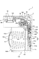
図1から図5は、本実施形態に係る紙幣処理装置の構成を示す図であり、図1は、全体構成を示す斜視図、図2は、開閉部材を装置本体の本体フレームに対して開いた状態を示す斜視図、図3は、挿入口から挿入される紙幣の搬送経路を概略的に示した右側面図、図4は、紙幣収容部に配設される押圧板を駆動するための動力伝達機構の概略構成を示す右側面図、そして、図5は、紙幣搬送機構を駆動するための駆動源及び駆動力伝達機構の概略構成を示す左側面図である。 FIG. 1 to FIG. 5 are diagrams showing the configuration of the banknote handling apparatus according to the present embodiment, FIG. 1 is a perspective view showing the overall configuration, and FIG. 2 is a diagram showing an opening / closing member opened with respect to the main body frame of the apparatus main body. FIG. 3 is a right side view schematically showing a transport path of a bill inserted from the insertion slot, and FIG. 4 is a diagram for driving a pressing plate disposed in the bill housing part. FIG. 5 is a right side view illustrating a schematic configuration of the power transmission mechanism, and FIG. 5 is a left side view illustrating a schematic configuration of a driving source and a driving force transmission mechanism for driving the bill conveyance mechanism.
本実施形態の紙幣処理装置1は、例えば、スロットマシン等の各種の遊技機に組み込み可能に構成されており、装置本体2と、この装置本体2に設けられ、多数の紙幣などを積層、収容することが可能な収容部(収容スタッカ;金庫)100とを備えている。この収容部100は、装置本体2に対して着脱可能であっても良く、例えば、図示されていないロック機構が解除された状態で、前面に設けられた取っ手101を引くことで、装置本体2から取り外すことが可能となっている。
The banknote handling
前記装置本体2は、図2に示すように、本体フレーム2Aと、本体フレーム2Aに対して一端部を回動中心として開閉されるように構成された開閉部材2Bとを有している。そして、これら本体フレーム2A及び開閉部材2Bは、図3に示すように、開閉部材2Bを本体フレーム2Aに対して閉じた際、両者の対向部分に紙幣が搬送される隙間(紙幣搬送路3)が形成されると共に、両者の前面露出側に、前記紙幣搬送路3に一致するようにして、紙幣挿入口5が形成されるよう構成されている。なお、前記紙幣挿入口5は、紙幣の短い辺側から装置本体2の内部に挿入できるようにスリット状の開口となっている。
As shown in FIG. 2, the apparatus
また、前記装置本体2内には、前記紙幣搬送路3に沿って、紙幣を搬送する紙幣搬送機構6と、紙幣挿入口5に挿入された紙幣を検知する挿入検知センサ7と、挿入検知センサ7の下流側に設置され、搬送状態にある紙幣の情報を読取る紙幣読取手段8と、この紙幣読取手段8に対して、紙幣を正確に位置決めして搬送するスキュー補正機構10と、紙幣がスキュー補正機構を構成する一対の可動片を通過したことを検知する可動片通過検知センサ12と、紙幣が紙幣収容部100に排出されたことを検知する排出検知センサ18とが設けられている。
Further, in the apparatus
以下、上記した各構成部材について、詳細に説明する。
前記紙幣搬送路3は、紙幣挿入口5から奥側に向けて延出しており、第1搬送路3Aと、前記第1搬送路3Aから下流側に向けて延出し、第1搬送路3Aに対して所定角度、下方側に向けて傾斜した第2搬送路3Bとを備えている。この第2搬送路3Bの下流側は、鉛直方向に向けて屈曲しており、その下流側端部には、紙幣収容部100に紙幣を排出する排出口3aが形成されて、ここから排出される紙幣は、鉛直方向に向けて、紙幣収容部100の導入口(受入口)103に送り込まれる。
Hereafter, each above-mentioned structural member is demonstrated in detail.
The
前記紙幣搬送機構6は、紙幣挿入口5から挿入された紙幣を挿入方向に沿って搬送可能にすると共に、挿入状態にある紙幣を紙幣挿入口5に向けて差し戻し搬送可能とする機構である。この紙幣搬送機構6は、装置本体2内に設置された駆動源であるモータ13(図5参照)と、このモータ13によって回転駆動され、紙幣搬送路3に紙幣搬送方向に沿って所定間隔おいて配設される搬送ローラ対(14A,14B)、(15A,15B)、(16A,16B)、及び(17A,17B)を備えている。
The
前記搬送ローラ対は、紙幣搬送路3に一部が露出するように設置されて、いずれも紙幣搬送路3の下側に設置される搬送ローラ14B,15B,16B及び17Bがモータ13によって駆動されるローラとなっており、上側に設置される搬送ローラ14A,15A,16A及び17Aが、これらのローラに対して従動するピンチローラとなっている。なお、紙幣挿入口5から挿入された紙幣を最初に挟持して奥側に搬送する搬送ローラ対(14A,14B)は、図2に示すように、紙幣搬送路3の中心位置に1箇所設置されており、その下流側に順次配置される搬送ローラ対(15A,15B)、(16A,16B)、及び(17A,17B)については、紙幣搬送路3の幅方向に沿って、所定間隔をおいて2箇所設置されている。
The pair of transport rollers is installed so that a part thereof is exposed in the
また、上記した紙幣挿入口5の近傍に配置される搬送ローラ対(14A,14B)については、通常は、上側の搬送ローラ14Aが下側の搬送ローラ14Bから離間した状態となっており、紙幣の挿入が挿入検知センサ7によって検知されると、上側の搬送ローラ14Aが下側の搬送ローラ14Bに向けて駆動され、挿入された紙幣を挟持するようになっている。
Moreover, about the conveyance roller pair (14A, 14B) arrange | positioned in the vicinity of the above-mentioned
すなわち、上側の搬送ローラ14Aについては、駆動源であるローラ昇降用モータ70(図6参照)によって、下側の搬送ローラ14Bに対して、当接/離間するように駆動制御される。この場合、スキュー補正機構10によって、挿入された紙幣の傾きを無くし紙幣読取手段8に対して位置合わせする処理(スキュー補正処理)が行われる際には、上側の搬送ローラ14Aは、下側の搬送ローラ14Bから離間して紙幣に対する負荷を解除し、スキュー補正処理が終了すると、再び、上側の搬送ローラ14Aが下側の搬送ローラ14Bに向けて駆動され、紙幣を挟持する。なお、駆動源については、モータ以外にもソレノイド等によって構成されていても良い。
That is, the
また、前記スキュー補正機構10は、スキューの補正を果たす左右一対の可動片10A(片側のみ図示)を備えており、スキュー補正機構用のモータ40を駆動することで、左右一対の可動片10Aを接近するように移動させ、これにより、紙幣に対するスキューの補正処理が成される。
Further, the
上記した紙幣搬送路3の下側に設置される搬送ローラ14B,15B,16B及び17Bは、図5に示すように、モータ13、及び各搬送ローラの駆動軸の端部に設置されるプーリ14C,15C,16C及び17Cを介して回転駆動される。すなわち、モータ13の出力軸には、駆動プーリ13Aが設置されており、上記した各搬送ローラの駆動軸の端部に設置されるプーリ14C,15C,16C及び17Cには、駆動プーリ13Aとの間で駆動ベルト13Bが巻回されている。なお、駆動ベルト13Bには、適所にテンションプーリが係合しており、弛みを防止している。
Conveying
上記した構成により、モータ13が正転駆動されると、前記搬送ローラ14B,15B,16B及び17Bは同期して正転駆動され、紙幣を挿入方向に向けて搬送し、モータ13が逆転駆動されると、前記搬送ローラ14B,15B,16B及び17Bは同期して逆転駆動され、紙幣を紙幣挿入口5側に向けて搬送する。
With the configuration described above, when the
前記挿入検知センサ7は、紙幣挿入口5に挿入された紙幣を検知した際に検知信号を発生するものであり、この検知信号が発せられると、モータ13が正転駆動され、紙幣を挿入方向に向けて搬送する。本実施形態の挿入検知センサ7は、搬送ローラ対(14A,14B)と、スキュー補正機構10との間に設置されており、光学式のセンサ、例えば、回帰反射型フォトセンサによって構成されているが、それ以外にも、機械式のセンサによって構成されていても良い。
The
また、前記可動片通過検知センサ12は、紙幣の先端が、スキュー補正機構10を構成する左右一対の可動片10Aを通過したことを検知した際に検知信号を発生するものであり、この検知信号が発せられると、モータ13の駆動が停止され、スキュー補正処理が成される。本実施形態の可動片通過検知センサ12は、前記紙幣読取手段8の上流側に設置されており、前記挿入検知センサと同様、光学式のセンサや機械式のセンサによって構成される。
The movable piece
また、前記排出検知センサ18は、通過する紙幣の後端を検知して、紙幣が紙幣収容部100に排出されたことを検知するものであり、第2搬送路3Bの下流側において、紙幣収容部100の受入口103の直前に配設されている。排出検知センサ18から検知信号が発せられると、モータ13の駆動が停止され、紙幣の搬送処理が終了する。この排出検知センサ18についても、前記挿入検知センサと同様、光学式のセンサや機械式のセンサによって構成される。
Moreover, the said discharge |
前記紙幣読取手段8は、スキュー補正機構10によってスキューが補正された状態で搬送される紙幣について、その紙幣情報を読取り、その有効性(真贋)を識別する。本実施形態では、紙幣読取手段8は、搬送される紙幣の両面側から光を照射し、その透過光と反射光を受光素子で検知することで読取を行うラインセンサを備えた構成になっており、前記第1搬送路3Aに設置されている。
The banknote reading means 8 reads the banknote information of a banknote conveyed in a state where the skew is corrected by the
本実施形態では、真贋の識別精度を高めるように、上記した紙幣読手段を利用して、搬送される紙幣の印刷部分に光を照射し、その透過光及び反射光を受光して、印刷部分における特徴点(特徴点の領域、抽出の仕方は任意である)が真正のものと一致するか否かを識別する第1の真贋判定処理と、前記透過光及び反射光のいずれか一方、又は両方を利用して、紙幣の両側の印刷長さ(印刷された領域全体の印刷長であっても良いし、特徴部分を抽出しておき、その特徴点間の印刷長であっても良い)を実測し、両面の印刷長に基づいて、その紙幣が真正なものか否かを識別する第2の真贋判定処理が成される。 In the present embodiment, in order to improve the accuracy of authenticity identification, the above-described bill reading means is used to irradiate the printed portion of the bill to be conveyed, receive the transmitted light and reflected light, and print the printed portion. A first authenticity determination process for identifying whether or not a feature point (a region of the feature point, an extraction method is arbitrary) matches a genuine one, and one of the transmitted light and reflected light, or Using both, the print length on both sides of the banknote (may be the print length of the entire printed area, or may be the print length between the feature points after extracting the characteristic part) And a second authenticity determination process for identifying whether or not the banknote is authentic based on the print lengths on both sides.
この場合、本発明は、上記した第2の真贋判定処理に特徴があり、この第2の真贋判定処理については、第1の真贋判定処理が実行された後に行われるようにしても良いし、第1の真贋判定処理の前に実行するようにしても良い。本実施形態では、後述するように、第1の真贋判定処理を実行した後、第2の真贋判定処理を行うよう構成されている。 In this case, the present invention is characterized in the second authenticity determination process described above, and the second authenticity determination process may be performed after the first authenticity determination process is executed. It may be executed before the first authenticity determination process. In the present embodiment, as described later, the second authenticity determination process is performed after the first authenticity determination process is executed.
上記した第1及び第2の真贋判定処理は、いずれも搬送される紙幣の表面の印刷領域に、発光手段から所定波長の光を照射し、当該紙幣を透過した光の透過光データ、並びに反射した光の反射光データを取得し、これを予め記憶されている真正紙幣の基準データと比較することで成される。 In both the first and second authenticity determination processes described above, light having a predetermined wavelength is irradiated from the light emitting means to the print area on the surface of the bill to be conveyed, and the transmitted light data of the light transmitted through the bill and the reflection are reflected. The reflected light data of the obtained light is acquired and compared with the reference data of the genuine banknote stored in advance.
この場合、真正の紙幣には、照射する光の波長(例えば、可視光や赤外光)によって、取得される画像データが異なる領域があることから、前記第1の真贋判定処理では、この点に着目し、複数の光源によって異なる波長(本実施形態では、赤色光及び赤外光を照射する)の光を紙幣に照射し、その透過光と反射光を検出することで、真贋の識別精度をより高めるようにしている。すなわち、赤色光と赤外光では、波長が異なることから、波長の異なる複数の光による透過光データや反射光データを紙幣の真贋判定に用いると、真券と偽札との特定領域を通過する透過光や特定領域から反射する反射光では、透過率、反射率がそれぞれ異なるという性質がある。このため、複数の波長の光源を用いることで、紙幣の真贋の識別精度をより高めるようにしている。 In this case, since the genuine banknote has a region in which the acquired image data differs depending on the wavelength of light to be irradiated (for example, visible light or infrared light), this point is determined in the first authenticity determination process. , By irradiating the bill with light of different wavelengths (in this embodiment, irradiating red light and infrared light) depending on a plurality of light sources, and detecting the transmitted light and reflected light, the authenticity of authenticity I try to raise more. That is, since red light and infrared light have different wavelengths, if transmitted light data or reflected light data from a plurality of lights having different wavelengths is used for determining the authenticity of a bill, it passes through a specific area between a genuine note and a counterfeit bill. Transmitted light and reflected light reflected from a specific region have properties that the transmittance and the reflectance are different. For this reason, the identification accuracy of the authenticity of a banknote is raised more by using the light source of a some wavelength.
なお、具体的な紙幣の真贋識別方法については、紙幣に照射する光の波長や照射領域により、様々な受光データ(透過光データ、反射光データ)を取得できるため、詳細に説明しないが、例えば、紙幣の透かし領域では、異なる波長の光でその領域の画像を見た場合、画像が大きく異なって見えることから、この部分を特定領域とし、当該特定領域における透過光データや反射光データを取得して、予め記憶手段(ROM)に記憶してある真券の同じ特定領域における正規データと比較して、識別対象となる紙幣が真券であるか偽札であるかを識別することが考えられる。このとき、金種に応じて特定領域を定めておき、この特定領域における透過光データや反射光データに所定の重み付けを設定しておき、真贋識別精度のさらなる向上を図ることも可能である。 In addition, about the specific authentication method of a banknote, since various light reception data (transmitted light data, reflected light data) can be acquired with the wavelength and irradiation area | region of the light irradiated to a banknote, although it does not explain in detail, for example, In the watermark area of banknotes, when viewing the image of that area with light of different wavelengths, the image looks very different, so this part is taken as a specific area, and transmitted light data and reflected light data in that specific area are acquired. Then, it is conceivable to identify whether the bill to be identified is a genuine note or a counterfeit note by comparing with genuine data in the same specific area of the genuine note stored in advance in the storage means (ROM). . At this time, it is also possible to determine a specific area in accordance with the denomination and set a predetermined weight to transmitted light data and reflected light data in this specific area to further improve the accuracy of authenticity identification.
また、前記第2の真贋判定処理では、上記した紙幣読取手段8によって、例えば、紙幣搬送方向に沿った画素情報として紙幣両面の画像情報を取得し、その搬送方向に沿った画素情報から、各面における印刷長を導き出して、この印刷長によって真贋の判定処理を行う。この第2の真贋判定処理は、印刷長が真正の紙幣とは異なっているものについては、偽物として排除するものであり、このような真贋判定処理を行うことで、紙幣の識別精度を、より高めることが可能となる。
Further, in the second authenticity determination process, for example, image information on both sides of the banknote is acquired as pixel information along the banknote conveyance direction by the above-described
ところで、紙幣は様々な環境下で用いられることから、紙幣全体として伸縮することがある(専ら、紙幣は、繊維質な材料によって形成されていることから、水分等を含んだ後、乾燥して収縮するケースが多いと考えられる)。上記のように、両面の印刷長を取得して真贋判定処理を行うことは、真贋判定の精度を向上する上では望ましいが、紙幣の収縮について考慮しておかないと、真正な紙幣であっても、偽物と判定(誤った判定処理)をしてしまう可能性がある。このため、第2の真贋判定処理を実行する上では、後述するような手法を用いることで、そのような誤った判定処理が成されないようにしている。 By the way, since bills are used in various environments, they may expand and contract as a whole bill (exclusively, since bills are made of a fibrous material, they contain moisture etc. and then dry. It is thought that there are many cases that shrink.) As described above, it is desirable to obtain the printing length on both sides and perform the authenticity determination process in order to improve the accuracy of the authenticity determination. However, there is a possibility that it is determined to be a fake (incorrect determination process). For this reason, when executing the second authenticity determination process, such an erroneous determination process is prevented from being performed by using a method as described later.
そして、上記した紙幣読取手段8は、後述するように、発光部を所定の間隔で点灯制御し、紙幣が通過する際の透過光及び反射光をラインセンサによって検知するものであることから、ラインセンサによって、所定の大きさを1単位とした複数の画素情報に基づいた画像データを取得することが可能となる。 And since the above-mentioned banknote reading means 8 controls the lighting of the light emitting part at a predetermined interval and detects transmitted light and reflected light when the banknote passes by a line sensor, as described later. The sensor makes it possible to acquire image data based on a plurality of pieces of pixel information with a predetermined size as one unit.
この場合、ラインセンサによって取得される画像データは、後述する変換部によって、画素毎に、明るさを有する色情報を含んだデータに変換される。なお、変換部において変換される明るさを有する画素毎の色情報とは、濃淡値すなわち濃度値(輝度値)に対応するものであって、例えば、1バイト情報として、その濃度値に応じて、0から255の数値(0:黒〜255:白)が各画素に割り当てられている。 In this case, the image data acquired by the line sensor is converted into data including color information having brightness for each pixel by a conversion unit described later. Note that the color information for each pixel having brightness that is converted by the conversion unit corresponds to a gray value, that is, a density value (luminance value), and is, for example, 1-byte information according to the density value. , 0 to 255 (0: black to 255: white) are assigned to each pixel.
このため、第1の真贋判定処理では、紙幣の所定の領域を抽出し、その領域に含まれる画素情報(濃度値)と、真券の同じ領域の画素情報とを用い、これらを適宜の相関式に代入して演算した相関係数により、真贋を識別することが可能である。或いは、上記した以外にも、透過光データや反射光データから、例えばアナログ波形を生成し、この波形の形状同士の比較で、真贋を識別することも可能である。 Therefore, in the first authenticity determination process, a predetermined area of the banknote is extracted, pixel information (density value) included in the area and pixel information of the same area of the genuine note are used, and these are appropriately correlated. The authenticity can be identified by the correlation coefficient calculated by substituting it into the equation. Alternatively, in addition to the above, for example, an analog waveform can be generated from transmitted light data or reflected light data, and authenticity can be identified by comparing the shapes of the waveforms.
また、第2の真贋判定処理では、紙幣の両面から得られた画像情報から、印刷領域に関して長さデータ(実測データ)を取得することが可能である。この場合、画素情報として取得される画像データは、ラインセンサの解像度にも依存するが、例えば、1画素が、紙幣の長さ方向において、0.508mm程度の解像度であれば、紙幣の搬送方向の全体の画素数から、その長さを取得する際、少なくとも印刷長が1〜2mm程度、異なるものについては偽物として排除することが可能となる。なお、さらに印刷長に基づく識別精度を高めるのであれば、ラインセンサの解像度を高めれば良いが、あまり識別精度を高めると、本物の紙幣であっても、単なる印刷時における僅かな作成誤差のものまで排除してしまう可能性があるため、ラインセンサとしては上記の解像度で十分と考えられる。 Further, in the second authenticity determination process, it is possible to obtain length data (actual measurement data) regarding the print region from the image information obtained from both sides of the bill. In this case, the image data acquired as pixel information also depends on the resolution of the line sensor. For example, if one pixel has a resolution of about 0.508 mm in the banknote length direction, the banknote transport direction When obtaining the length from the total number of pixels, it is possible to exclude at least a printing length of about 1 to 2 mm as a fake. Note that if the identification accuracy based on the print length is further increased, the resolution of the line sensor may be increased. However, if the identification accuracy is increased too much, even if it is a real banknote, it has a slight production error during printing. The above resolution is considered sufficient for a line sensor.
ここで、上記した紙幣読取手段8の構成について、図2及び図3を参照して詳細に説明する。 Here, the configuration of the bill reading means 8 will be described in detail with reference to FIGS.
上記した紙幣読取手段8は、開閉部材2B側に配設され、搬送される紙幣の上側に赤外光及び赤色光を照射可能とした第1発光部80aを具備した発光ユニット80と、本体フレーム2A側に配設された受発光ユニット81とを有している。
The bill reading means 8 described above is disposed on the opening / closing
この受発光ユニット81は、紙幣を挟むようにして第1発光部80aと対向する受光センサを具備した受光部81aと、受光部81aの紙幣搬送方向両側に隣接して配設され、赤外光及び赤色光を照射可能とした第2発光部81bとを有している。
The light receiving / emitting
前記受光部81aと対向配置された第1発光部80aは透過用の光源として機能する。この第1発光部80aは、図2に示すように、一端に取り付けたLED素子80bからの光を、内部に設けた導光体80cを通して発光する合成樹脂製の矩形棒状体によって構成されている。このような構成の第1発光部は、受光部81a(受光センサ)と平行にライン状に配設されており、簡単な構成で、搬送される紙幣の搬送路幅方向全体の範囲に対して全体的に均一に照射することが可能となる。
The first
前記受発光ユニット81の受光部81aは、紙幣搬送路3に対して交差方向に伸延し、かつ受光部81aに設けた図示しない受光センサの感度に影響を与えない程度の幅を有する帯状に形成された薄肉の板状に形成されている。なお、前記受光センサは、受光部81aの厚み方向の中央に、複数のCCD(Charge Coupled Device)をライン状に設けるとともに、このCCDの上方位置に、透過光及び反射光を集光させるように、ライン状にグリンレンズアレイ81cを配置した所謂ラインセンサとして構成されている。このため、真贋判定対象となる紙幣に向けて照射された第1発光部80aや第2発光部81bからの赤外光や赤色光の透過光あるいは反射光を受光し、受光データとして、その輝度に応じた濃淡データ(明るさの情報を含んだ画素データ)や、この濃淡データから二次元画像を生成することが可能となっている。
The
また、受発光ユニット81の第2発光部81bは反射用の光源として機能する。この第2発光部81bは、第1発光部80aと同様、一端に取り付けたLED素子81dからの光を、内部に設けた導光体81eを通して全体的に均一に照射可能とした合成樹脂製の矩形棒状体によって構成されている。この第2発光部81bについても、受光部81a(ラインセンサ)と平行にライン状に配設して構成されている。
Further, the second
前記第2発光部81bは、例えば45度の仰角で光を紙幣に向けて照射可能としており、紙幣からの反射光を受光部81aで受光するように配設されている。この場合、第2発光部81bから照射された光が受光部81aへ45度で入射するようにしているが、入射角は45度に限定されるものではなく、紙幣の表面に対して濃淡なく均一に光が照射できれば、その設置状態については適宜設定することができる。このため、第2発光部81b、受光部81aの配置については、紙幣処理装置の構造に応じて、適宜設計変更が可能である。また、前記第2発光部81bについては、受光部81aを挟んで両サイドに設置して、両側からそれぞれ入射角45度で光を照射するようにしている。これは、紙幣表面に傷や折皺などがある場合、これら傷や折皺部分に生じた凹凸に光が片側からのみ照射された場合、どうしても凹凸の部分においては光が遮られて陰になってしまう箇所が生じることがある。このため、両側から光を照射することにより、凹凸の部分において陰ができることを防止して、片側からの照射よりも精度の高い画像データを得ることを可能としている。もちろん、第2発光部81bについては、片方のみに設置した構成であっても良い。
The second
なお、上記した発光ユニット80、受発光ユニット81の構成や配置などは、本実施形態に限定されるものではなく、適宜変形することが可能である。
The configurations and arrangements of the
また、上記した発光ユニット80、及び受発光ユニット81における各第1発光部80a、及び第2発光部81bでは、紙幣の読取り時、図6のタイミングチャートに示すように赤外光と赤色光が、所定の間隔で点灯制御される。すなわち、第1発光部80a及び第2発光部81bにおける赤色光と赤外光の透過用の光源と、赤色光と赤外光の反射用の光源からなる4つの光源は、一定の間隔(所定の点灯間隔)で点灯、消灯を繰り返し、各光源の位相を重ねることなく、2つ以上の光源が同時に点灯することがないように点灯制御される。換言すれば、ある光源が点灯しているときには、他の3つの光源は消灯するように点灯制御される。これにより、本実施形態のように、1つの受光部81aであっても、各光源の光を一定間隔で検出し、赤色光の透過光及び反射光、赤外光の透過光及び反射光による紙幣の印刷領域の濃淡データからなる画像を読取ることができ、また、両面の印刷長を測定することが可能となる。この場合、点灯間隔が短くなるように制御することで、解像度を高めることも可能である。
Further, in each of the first
また、上述した紙幣などを収容する紙幣収容部100は、上記した紙幣読取手段8で真性と識別された紙幣を順次、積層、収容する。
Moreover, the
図3から図5に示すように、紙幣収容部100を構成する本体フレーム100Aは、略直方体形状に構成されており、その前壁102aの内側には、付勢手段(付勢バネ)106の一端が取り付けられ、その他端には、上記した受入口103を介して送り込まれる紙幣を順次、積層する載置プレート105が設けられている。このため、載置プレート105は、前記付勢手段106を介して、後述する押圧板115側に向けて付勢された状態になっている。
As shown in FIGS. 3 to 5, the
本体フレーム100A内には、受入口103に連続するように、落下する紙幣をそのまま待機、保持させる押圧待機部108が設けられている。押圧待機部108の載置プレート側の両サイドには、鉛直方向に延出して一対の規制部材110が配置されている。この一対の規制部材110の間には、載置プレート105上に紙幣が順次、積層されるに際して、押圧板115が通過するように、開口部が形成されている。
In the
また、本体フレーム100A内の両サイド壁には、載置プレート105が付勢手段106によって押圧された際、載置プレートが当て付くように、突出壁が形成されている。この突出壁は、載置プレート105上に紙幣が順次、積層されて、前記付勢手段106によって載置プレートが付勢された際、最上の紙幣の両サイドを当て付け、積層される紙幣を安定して保持する役目を果たす。
In addition, projecting walls are formed on both side walls in the
さらに、本体フレーム100A内には、受入口103から押圧待機部108に落下した紙幣を載置プレート105に向けて押圧する押圧板115が配設されている。この押圧板115は、前記一対の規制部材110の間に形成された開口部を往復移動できる程度の大きさに構成されており、この開口部内に入り込んで、紙幣を載置プレート105に押し付ける位置(押圧位置)と、前記押圧待機部108を開放する位置(初期位置)との間で往復駆動される。この場合、押圧板115の押し込み動作によって、紙幣は撓みながら開口部を通過して、載置プレート105上に載置される。
Further, a
前記押圧板115は、本体フレーム100A内に配設される押圧板駆動機構120を介して、上記したように往復駆動される。押圧板駆動機構120は、押圧板115を図3及び図4の矢印A方向に往復移動可能となるように、両端が押圧板115に軸支された一対のリンク部材115a,115bを備えており、これらのリンク部材115a,115bはX字状に連結され、それぞれの反対側の端部は、垂直方向(矢印B方向)に移動可能に設置された可動部材122に軸支されている。この可動部材122には、ラックが形成されており、このラックには、押圧板駆動機構120を構成するピニオンが噛合している。
The
このピニオンには、図4に示すように、押圧板駆動機構120を構成する収容部側ギヤトレイン124が連結されている。この場合、本実施形態においては、図45に示すように、上述した装置本体2内に、駆動源(モータ20)と、このモータ20に順次噛合する本体側ギヤトレイン21が配設されており、紙幣収容部100を装置本体2に装着すると、本体側ギヤトレイン21が収容部側ギヤトレイン124に連結するようになっている。すなわち、収容部側ギヤトレイン124は、ピニオンと同軸上に配設されるギヤ124B、及びこれに順次噛合するギヤ124C,124Dを備えており、紙幣収容部100を装置本体2のフレーム2Aに対して着脱する際、ギヤ124Dが、本体側ギヤトレイン21の最終ギヤ21Aと噛合、離間するよう構成されている。
As shown in FIG. 4, a housing part
この結果、上記した押圧板115は、装置本体2に設けられたモータ20が回転駆動されることで、本体側ギヤトレイン21、及び押圧板駆動機構120(収容部側ギヤトレイン124、可動部材122に形成されるラック、及びリンク部材115a,115b等)を介して、矢印A方向に往復駆動される。
As a result, the above-described
また、本体フレーム100Aには、前記受入口103から搬入される紙幣に対して接触可能な搬送部材150が設置されている。この搬送部材150は、搬入される紙幣に接触して、安定して紙幣を押圧待機部108の適正位置(押圧板115で紙幣を押圧した際、紙幣が左右に片寄ることなく、安定して押圧できる位置)に案内する役目を果たす。本実施形態では、この搬送部材は、押圧待機部108に臨むように設置されたベルト状の部材(以下、ベルト150とする)によって構成されている。
The
この場合、ベルト150は、紙幣に対して搬入方向に沿って延在するように設置されており、搬入方向の両端部に回転可能に支持された一対のプーリ150A,150Bに巻回されている。また、ベルト150は、受入口103の領域に回転可能に支持された軸方向に延出する搬送ローラ150Cと当接しており、受入口103に搬入された紙幣を挟持して、紙幣をそのまま押圧待機部108に案内するようにしている。さらに、本実施形態では、前記ベルト150は、紙幣の両サイドの表面に接触可能となるように、上記した押圧板115を挟むようにして左右一対設けられている。なお、ベルト150は、両端におけるプーリ150A,150Bの巻回以外に、中間位置でテンションプーリを当て付け、弛みを防止するようにしても良い。
In this case, the
前記一対のベルト150は、装置本体2内に設置される上述した複数の搬送ローラを駆動するモータ13によって駆動されるようになっている。具体的には、図5に示すように、モータ13によって駆動される上述した駆動ベルト13Bは、駆動力伝達用のプーリ13Dに巻回されており、このプーリ13Dに順次設置される動力伝達用のギヤトレイン13Eには、受入口103側に回転可能に支持されているプーリ150Aの支軸の端部に設置されたギヤトレイン153が噛合するようになっている。すなわち、紙幣収容部100が装置本体2に装着された際、ギヤトレイン13Eの最終ギヤには、ギヤトレイン153の入力ギヤが噛合するようになっており、一対のベルト150は、モータ13の回転駆動により、上述した紙幣搬送用の搬送ローラ14B,15B,16B,17Bと一体的に回転駆動されるようになっている。
The pair of
上述したように、紙幣が紙幣挿入口5を介して内部に挿入されると、紙幣は、上記した紙幣搬送機構6によって、紙幣搬送路3内で移動して行く。紙幣搬送路3は、図3に示すように、紙幣挿入口5から奥側に向けて延出した第1搬送路3Aと、前記第1搬送路3Aから下流側に向けて延出し、第1搬送路3Aに対して所定角度傾斜した第2搬送路3Bとを備えており、この第2搬送路3Bには、不正行為等により、紙幣挿入口5側に向けて紙幣の搬送を阻止するシャッタ部材170が設置されている。
As described above, when a bill is inserted into the bill via the
次に、上述した紙幣搬送機構6、紙幣読取手段8等の駆動部材の駆動を制御する制御手段200について、図7のブロック図を参照して説明する。
Next, the control means 200 which controls the drive of drive members, such as the
図7のブロック図に示す制御手段200は、上記した各駆動装置の動作を制御する制御基板210を備えており、この制御基板210上には、各駆動装置の駆動を制御すると共に、紙幣識別手段を構成するCPU(Central Processing Unit)220と、ROM(Read Only Memory)222と、RAM(Random
Access Memory)224と、真贋判定部230とが実装されている。
The control means 200 shown in the block diagram of FIG. 7 includes a
Access Memory) 224 and an
前記ROM222には、紙幣搬送機構用のモータ13、押圧板駆動用のモータ20、スキュー補正機構用のモータ40、ローラ昇降用のモータ70等、各種駆動装置の作動プログラムや、真贋判定部230における真贋判定プログラム等の各種プログラム等、恒久的なデータが記憶されている。
In the
前記CPU220は、ROM222に記憶されている前記プログラムに従って作動して、I/Oポート240を介して上述した各種駆動装置との信号の入出力を行い、紙幣処理装置の全体的な動作制御を行う。すなわち、CPU220には、I/Oポート240を介して、紙幣搬送機構用のモータ13、押圧板駆動用のモータ20、スキュー補正機構用のモータ40、ローラ昇降用のモータ70が接続されており、これらの駆動装置は、ROM222に格納された作動プログラムに従って、CPU220からの制御信号により動作が制御される。また、CPU220には、I/Oポート240を介して、挿入検知センサ7、可動片通過検知センサ12、排出検知センサ18からの検知信号が入力されるようになっており、これら検知信号に基づいて、上記した各種駆動装置の駆動制御が行われる。
The
さらに、CPU220には、I/Oポート240を介して、上述した紙幣読取手段8における受光部81aから、識別対象物に照射された光の透過光や反射光に基づく検知信号が入力されるようになっている。
Further, the
前記RAM224には、CPU220が作動する際に用いるデータやプログラムが一時的に記憶されると共に、識別対象物である紙幣の受光データ(複数の画素によって構成される画像データ)を取得して一時的に記憶する機能を備えている。
The
前記真贋判定部230は、搬送される紙幣について上記した第1の真贋判定処理、及び第2の真贋判定処理を実施し、その紙幣の真贋を識別する機能を有する。この真贋判定部230は、前記RAM224に格納された識別対象物の受光データに関し、画素毎に、明るさを有する色情報(濃度値)を含んだ画素情報に変換する変換部231と、前記変換部231で変換された画素情報を元にして、搬送された紙幣の印刷長を特定したり、その印刷長に基づいて後述するような補正処理を実施する等、反射光及び透過光から得られる紙幣に関する画像データを処理する機能を備えたデータ処理部231とを有する。
The
また、真贋判定部230は、真正な紙幣に関する基準データを格納した基準データ記憶部233と、前記データ処理部231において真贋対象となる紙幣についての各種のデータ処理が施された比較データと、基準データ記憶部233に格納されている基準データとを比較し、真贋判定の処理を行う比較判定部235と、を備えている。この場合、前記基準データ記憶部233には、例えば、上記した第1の真贋判定処理を実施するに際して用いられる真正紙幣に関する画像データや、上記した第2の真贋判定処理において用いられる真正紙幣に関する印刷長の基準値、及びその基準値から許容される許容範囲データ等が記憶されている。
In addition, the
なお、上記した基準データについては、専用の基準データ記憶部233に記憶させているが、これを上記したROM222に記憶させておいても良い。また、比較対象時に参照される基準値や許容範囲データについては、予め基準データ記憶部233に記憶させておいても良いが、例えば、後述する第2の真贋判定処理のように、所定枚数の真券を、紙幣搬送機構6を通して搬送させながら受光データを取得し、ここから基準値や許容範囲を算出して基準データとして記憶する構成であっても良い。
The above-described reference data is stored in the dedicated reference data storage unit 233, but may be stored in the
さらに、CPU220には、I/Oポート240を介して、上述した紙幣読取手段8における第1発光部80aと、第2発光部81bが接続されている。これら第1発光部80a及び第2発光部81bは、上記したROM222に格納された動作プログラムに従い、CPU220からの制御信号によって、発光制御回路260を介して、点灯間隔、及び消灯が制御される。
Furthermore, the
次に、本発明の特徴である第2の真贋判定処理の具体的な処理方法の一例について説明する。 Next, an example of a specific processing method of the second authenticity determination process that is a feature of the present invention will be described.
上記したように、紙幣読取手段8は、紙幣搬送機構6によって搬送された紙幣に対し、前記第1発光部80a、及び第2発光部81bから光(赤色光、赤外光)を照射し、その透過光や反射光を受光部(ラインセンサ)81aで受光して紙幣の読取りを実行する。この読取りに際しては、紙幣の搬送処理が行われている間、所定の大きさを1単位(例えば、搬送方向における1ピクセルが0.508mm)とする多数の画素情報を取得することが可能であり、このようにして取得された多数の画素(複数の画素)によって構成される画像データは、RAM224などの記憶手段に記憶される。なお、ここで記憶される多数の画素によって構成される画像データは、変換部232によって、画素毎に、明るさを有する色情報(濃度値に応じて0から255の数値(0:黒〜255:白)が割り当てられた色情報)を含んだ情報に変換される。
As described above, the bill reading means 8 irradiates the bills conveyed by the
このように、ラインセンサで得られた画像を、変換部によって明るさを有する色情報(濃度値)を含む画素情報に変換することで、搬送される紙幣の一方の面と、他方の面の印刷長を実測することが可能となる。例えば、図8に示すように、紙幣を搬送(D1方向への搬送)する際、非印刷領域から印刷領域に移行すると、印刷領域では画素情報の濃度値は低くなる。従って、幅方向D2における平均の画素情報の濃度値を測定し、その変位する位置を閾値を設定して検出することで、紙幣両面について、所定の領域の印刷長R(ここでは、長手方向に亘る全ての印刷領域が該当する)に関する実測データを取得することが可能となる。 Thus, by converting the image obtained by the line sensor into pixel information including color information (density value) having brightness by the conversion unit, one side of the banknotes to be conveyed and the other side It is possible to actually measure the print length. For example, as illustrated in FIG. 8, when the banknote is transported (transported in the D1 direction), the density value of the pixel information becomes low in the printing area when the non-printing area is shifted to the printing area. Accordingly, by measuring the density value of the average pixel information in the width direction D2 and detecting the position where the pixel information is displaced by setting a threshold value, the printing length R (here, in the longitudinal direction) of a predetermined area is detected on both sides of the bill. It is possible to obtain actual measurement data relating to all of the print areas.
そして、上記したように得られる紙幣両面の実測データを利用して、所定枚数の真券の紙幣を基に、基準値、及びその基準値に対する許容範囲を設定することが可能である。これは、真券の紙幣であっても、印刷時のズレなどの影響により多少の偏差が生じていることから、まず、多数の紙幣を参照して基準値を定めておき、その基準値から、本物であると許容される許容範囲について設定することとしている。 And it is possible to set a reference value and an allowable range for the reference value based on a predetermined number of genuine bills using actual data on both sides of the bill obtained as described above. This is because even if it is a genuine note banknote, there is some deviation due to the influence of misalignment at the time of printing, so first, reference values are determined with reference to many banknotes, and from the reference value The allowable range allowed to be genuine is set.
ここでは、統計的な見地に基づいて、基準値及び許容範囲を設定する例について説明する。 Here, an example in which the reference value and the allowable range are set based on a statistical viewpoint will be described.
例えば、真券の紙幣50枚を紙幣読取手段8で読取り、その長さについて実測データを取得する。図9は、真券紙幣50枚の一方の面における実測データ例を示しており、その長さ(X)は、画素数(1ピクセル;0.508mm)によって特定されている。このようにして得られる実測データから平均値(μ)を取得し、各紙幣の印刷領域の長さの偏差(X−μ)を算出すると共に、その分散((X−μ)2 の平均)を算出する。そして、得られた分散から、標準偏差(σ)を取得することで、その許容範囲を設定することが可能である。 For example, 50 bills of true bills are read by the bill reading means 8 and actual measurement data is acquired for the length. FIG. 9 shows an example of actual measurement data on one side of 50 genuine bills, and the length (X) is specified by the number of pixels (1 pixel; 0.508 mm). The average value (μ) is obtained from the actually measured data thus obtained, and the deviation (X−μ) of the length of the printing area of each banknote is calculated and its variance (average of (X−μ) 2 ). Is calculated. Then, by obtaining the standard deviation (σ) from the obtained variance, the allowable range can be set.
すなわち、紙幣の印刷領域の基準値については、多数の真券の紙幣の平均値(μ)によって特定することで、印刷領域のバラツキの基準となる値を特定することができ、その特定された基準値から、本実施形態では、±3σの範囲を許容範囲として設定するようにしている。もちろん、許容範囲については、偽造券の精度を考慮して任意に設定することが可能である。 In other words, the reference value of the bill printing area can be specified by specifying the average value (μ) of a large number of genuine bills, whereby the reference value for the variation in the printing area can be specified. From the reference value, in this embodiment, a range of ± 3σ is set as an allowable range. Of course, the allowable range can be arbitrarily set in consideration of the accuracy of counterfeit tickets.
図9に示す表の例示では、真券の紙幣50枚の所定の印刷長の平均値(μ)、すなわち基準値は264.36、分散は10.27、標準偏差は3.20と算出されるため、この平均値、及び標準偏差(単位はピクセル)が、基準データ(辞書データ)として、上記した基準データ記憶部233に記憶される。そして、このような基準データについては、もう一方の面についても実行され、紙幣の両面について、所定の印刷領域について印刷長に関する基準値及び許容範囲が特定される。 In the example of the table shown in FIG. 9, the average value (μ) of the predetermined print length of 50 genuine bills, that is, the reference value is 264.36, the variance is 10.27, and the standard deviation is calculated as 3.20. Therefore, the average value and the standard deviation (unit is pixel) are stored in the reference data storage unit 233 as reference data (dictionary data). Such reference data is also executed for the other side, and for both sides of the bill, the reference value and allowable range regarding the print length are specified for a predetermined print area.
図10は、上記したような手法で導き出される分散状態を示したグラフであり、基準値である(μ)を中心として、(μ±3σ)を許容範囲R1として設定してある。 FIG. 10 is a graph showing the dispersion state derived by the method as described above, and (μ ± 3σ) is set as the allowable range R1 with the reference value (μ) as the center.
次に、実際に紙幣が搬送されて、第2の真贋判定処理で紙幣の真贋を識別する際には、まず、その紙幣読取手段8を通過する紙幣の両側から、上記した手順と同様な手順によって、紙幣の両面について実測データを取得する。 Next, when the banknote is actually conveyed and the authenticity of the banknote is identified in the second authenticity determination process, the same procedure as the above-described procedure is first performed from both sides of the banknote passing through the banknote reading means 8. The actual measurement data is acquired for both sides of the bill.
実測したデータについて、両面が共に、図10に示すグラフの許容範囲R1(両面それぞれに設定されている)に存在すれば、その紙幣は真正と判定される。また、一方の面の実測データが、上記した許容範囲R1に存在しなければ、その紙幣については、真偽が疑わしいことから、その裏面の実測データについて、補正処理を施す。これは、例えば、搬送された紙幣が、水分などの影響により収縮しているようなケースでは、本物の紙幣であっても、実測データ(表面とする)が、図10のグラフの点P1のような位置にあることが考えられる。或いは、実測データが、このような点P1に位置していれば、それは偽造に基づいて印刷長が短くなっているケースも考えられる。 If both sides of the measured data are within the allowable range R1 (set on both sides) of the graph shown in FIG. 10, the bill is determined to be authentic. Moreover, since the authenticity of the banknote is doubtful if the actual measurement data of one surface does not exist in the above-described allowable range R1, correction processing is performed on the actual measurement data of the back surface. This is because, for example, in a case where the conveyed banknote is contracted due to the influence of moisture or the like, even if it is a real banknote, the measured data (assumed to be the surface) is the point P1 in the graph of FIG. It is conceivable that it is in such a position. Alternatively, if the measured data is located at such a point P1, it may be considered that the print length is shortened based on forgery.
この場合、本物の紙幣であれば、水分等を含んだ後に乾燥したなどの影響によって収縮が生じていると、裏面の印刷領域も同様に収縮していることから、表面の実測データに基づいて裏面の実測データについて補正処理を行い、その補正した実測データが上記した許容範囲R1に存在していれば、それは真正と判定することが可能となる。もちろん、表面のみの実測データが短いような偽物の紙幣であれば、補正処理を実施すると、裏面の実測データは、許容範囲R1から外れることとなる。 In this case, if it is a real banknote, if the shrinkage occurs due to the effect of drying after containing moisture etc., the printed area on the back side is also shrinking in the same way. If correction processing is performed on the actual measurement data on the back surface and the corrected actual measurement data is present in the above-described allowable range R1, it can be determined as authentic. Of course, if it is a fake banknote whose actual data only on the front surface is short, the actual data on the back surface will be out of the allowable range R1 when the correction process is performed.
上記した例を参照して具体的に説明すると、表面の実測データが、例えば、図10に示すグラフの点P1や点P2で示す領域にあった場合、表面の補正値(r)を算出する。この表面の補正値(r)は、例えば、[1+(l−μ)/μ]によって導き出すことができる(l;表面の印刷領域の実測値、μ;表面の印刷領域の平均値)。 More specifically, with reference to the above-described example, for example, when the surface measurement data is in the area indicated by the points P1 and P2 in the graph shown in FIG. 10, the correction value (r) of the surface is calculated. . The correction value (r) of the surface can be derived, for example, by [1+ (1−μ) / μ] (l: measured value of the printed area on the surface, μ: average value of the printed area on the surface).
そして、得られた補正値(r)に対し、裏面の印刷領域の実測値(L)との間で、除算処理(L)/(r)を実施することで、裏面についての実測データに関する補正値(r´)を導き出すことができ、この裏面についての実測データに関する補正値(r´)が、裏面について予め設定されている許容範囲R1(μ±3σ)に存在すれば、それは、表面と同様に収縮したものと評価して、真正と判定される。そして、この補正処理において、裏面の補正値が許容範囲R1から逸脱していれば、それは偽物と判定される。 Then, the division processing (L) / (r) is performed on the obtained correction value (r) with the actual measurement value (L) of the printed area on the back surface, thereby correcting the measurement data on the back surface. A value (r ′) can be derived, and if a correction value (r ′) relating to the actual measurement data for this back surface is present in the allowable range R1 (μ ± 3σ) preset for the back surface, Similarly, it is judged as authentic by evaluating that it contracted. In this correction processing, if the correction value on the back surface deviates from the allowable range R1, it is determined to be fake.
なお、上記したような補正処理については、一方の面の実測データが、許容範囲R1以外のとき実施すれば良いが、許容範囲R1以下(図10のグラフの点P1で示される領域)となったときにのみ実施するようにしても良い。すなわち、通常、紙幣は膨張して伸びるようなケースは殆どないと考えられることから、許容範囲R1以外であっても、それが許容範囲R1以上(図10のグラフの点P2で示される領域)であるような場合、それは直ちに偽物であると判定するようにしても良い。このように構成することで、補正処理を簡略化することが可能となる。 The correction process as described above may be performed when the measured data on one surface is outside the allowable range R1, but is below the allowable range R1 (region indicated by the point P1 in the graph of FIG. 10). You may make it carry out only when. That is, normally, it is considered that there is almost no case where the banknote expands and extends, so even if it is outside the allowable range R1, it is not less than the allowable range R1 (region indicated by the point P2 in the graph of FIG. 10). In such a case, it may be determined immediately that it is a fake. With this configuration, the correction process can be simplified.
次に、上述した制御手段200によって実行される紙幣処理装置1における紙幣の処理動作について、図11〜図17のフローチャートに従って説明する。
Next, the bill processing operation in the
操作者が紙幣を紙幣挿入口5に挿入する際、紙幣挿入口の近傍に設置される搬送ローラ対(14A,14B)は、初期状態において離間した状態にある(後述するST16,ST56参照)。また、押圧板115は、押圧板115を駆動する一対のリンク部材115a,115bが押圧待機部108に位置しており、紙幣が一対のリンク部材115a,115bによって受入口103から押圧待機部108に搬入できない待機位置に設定されている。すなわち、この状態では、一対の規制部材110の間に形成された開口部に押圧板115が入り込んでいるため、開口部を介して紙幣収容部内に収容されている紙幣を抜き取ることができない状態となっている。
When the operator inserts a bill into the
さらに、搬送ローラ対(14A,14B)の下流側に位置するスキュー補正機構10を構成する一対の可動片10Aは、初期状態において、あらゆる紙幣の引き抜きができないように最小幅(例えば一対の可動片10Aの間隔が52mm;後述するST15,ST57参照)に移動した状態にある。
Further, the pair of
上記した搬送ローラ対(14A,14B)の初期状態では、皺のある紙幣であっても、操作者は容易に挿入することができる。そして、挿入検知センサ7によって紙幣の挿入が検知されると(ST01)、上述した押圧板115の駆動用のモータ20を所定量逆転駆動し(ST02)、押圧板115を初期位置に移動させる。すなわち、挿入検知センサ7によって紙幣の挿入が検知されるまでは、前記押圧板115は、一対の規制部材110の間に形成された開口部に移動された状態となっており、開口部を介して紙幣が通過できないように設定されている。
In the initial state of the transport roller pair (14A, 14B) described above, the operator can easily insert even a banknote with a hook. When insertion of the banknote is detected by the insertion detection sensor 7 (ST01), the
押圧板115が待機位置から初期位置に移動されると、押圧待機部108は開放状態となり(図4参照)、紙幣は、紙幣収容部100内に搬入可能な状態となる。すなわち、モータ20を所定量逆転駆動することで、押圧板115は、本体側ギヤトレイン21、及び押圧板駆動機構120(収容部側ギヤトレイン124、可動部材122に形成されるラック、及びリンク部材115a,115b)を介して、前記待機位置から初期位置に移動される。
When the
また、上述したローラ昇降用モータ70を駆動し、上側の搬送ローラ14Aを下側の搬送ローラ14Bに当接するように移動させる。これにより、挿入された紙幣は搬送ローラ対(14A,14B)によって挟持される(ST03)。
Further, the above-described roller raising / lowering
次いで、紙幣搬送路の開放処理が成される(ST04)。この開放処理は、図14に示すフローチャートに示すように、述したスキュー補正機構用のモータ40を逆転駆動することで、一対の可動片10Aを互いに離間する方向に駆動することで成される(ST100)。このとき、一対の可動片10Aの位置を検知する可動片検知センサによって、一対の可動片10Aが所定位置(最大幅位置)に移動したことが検知されると(ST101)、モータ40の逆転駆動が停止される(ST102)。この搬送路開放処理により、一対の可動片10A内に紙幣が進入できる状態になっている。なお、このST04の前段階では、紙幣搬送路3は、後述する搬送路閉鎖処理(ST15,ST57)によって閉鎖された状態にあるが、このように、紙幣挿入前に紙幣搬送路3を閉じておくことで、例えば、不正目的などで紙幣挿入口から板状の部材を挿入して、ラインセンサなどの素子を破損させることを防止することができる。
Subsequently, the banknote conveyance path opening process is performed (ST04). As shown in the flowchart of FIG. 14, the release process is performed by driving the pair of
次いで、紙幣搬送用のモータ13が正転駆動される(ST05)。紙幣は、搬送ローラ対(14A,14B)によって装置内部に搬送され、スキュー補正機構10よりも下流側に配設されている可動片通過検知センサ12が紙幣の先端を検知すると、紙幣搬送用のモータ13は停止される(ST06,ST07)。このとき、紙幣は、スキュー補正機構10を構成する一対の可動片10A間に位置している。
Next, the
引き続き、上述したローラ昇降用モータ71を駆動し、紙幣を挟持した状態となっている搬送ローラ対(14A,14B)を離間させる(ST08)。このとき、紙幣には、何等、負荷が作用していない状態となる。 Subsequently, the roller raising / lowering motor 71 described above is driven to separate the conveying roller pair (14A, 14B) that is in a state of sandwiching a bill (ST08). At this time, the bill is not subjected to any load.
そして、この状態でスキュー補正作動処理を行う(ST09)。このスキュー補正作動処理は、上述したスキュー補正機構用のモータ40を正転駆動することで、一対の可動片10Aを互いに接近する方向に駆動することで成される。すなわち、このスキュー補正作動処理は、図12のフローチャートに示すように、上述したモータ40を正転駆動することで、一対の可動片10Aを、互いに接近する方向に移動する(ST110)。この可動片の移動は、制御手段における基準データ記憶部に登録されている紙幣の最小幅(例;幅62mm)となるまで実行され、これにより、紙幣は、両側に当て付く可動片10Aによって、スキューが補正され、正確な中心位置となるように位置決めされる。
Then, skew correction operation processing is performed in this state (ST09). This skew correction operation process is performed by driving the pair of
上述したようなスキュー補正作動処理が終了すると、引き続き、搬送路開放処理が実行される(ST10)。これは、上述したスキュー補正機構用のモータ40を逆転駆動することで、一対の可動片10Aを離間する方向に移動することで成される(図14のST100〜ST102参照)。
When the skew correction operation process as described above is completed, the conveyance path opening process is subsequently executed (ST10). This is achieved by moving the pair of
続いて、上述したローラ昇降用モータ70を駆動し、上側の搬送ローラ14Aを下側の搬送ローラ14Bに当接するように移動させ、紙幣を搬送ローラ対(14A,14B)に挟持させる(ST11)。その後、紙幣搬送用のモータ13を正転駆動して紙幣を装置内部に向けて搬送し、紙幣が紙幣読取手段8を通過する際に、紙幣の読取処理を開始する(ST12,ST13)。
Subsequently, the roller raising / lowering
紙幣の読取処理においては、図6のタイミングチャートに示すように、上記した第1発光部80a及び第2発光部81bにおける赤色光と赤外光の透過用の光源と、赤色光と赤外光の反射用の光源からなる4つの光源が、一定の間隔で点灯、消灯を繰り返し、しかも、各光源の位相を重ねることなく、2つ以上の光源が同時に点灯することがないように点灯制御する。換言すれば、ある光源が点灯しているときには、他の3つの光源は消灯するように点灯制御する。これにより、本実施形態のように、1つの受光部81aであっても、各光源の光を一定間隔で検出し、赤色光の透過光及び反射光、赤外光の透過光及び反射光による識別対象物の印刷領域の濃淡データからなる画像を読取ることができる。
In the bill reading process, as shown in the timing chart of FIG. 6, a light source for transmitting red light and infrared light, red light, and infrared light in the first
そして、搬送される紙幣が紙幣読取手段8を通過して、紙幣の後端が、可動片通過検知センサ12によって検知されると(ST14)、紙幣搬送路3の閉鎖処理が実行される(ST15)。この処理においては、まず、図16のフローチャートに示すように、紙幣の後端が、可動片通過検知センサ12によって検知された後、上述したモータ40を正転駆動することで、一対の可動片10Aを、互いに接近する方向に移動する(ST130)。次に、可動片検知センサによって、可動片10Aが所定位置(最小幅位置、例えば52mm)に移動したことが検知されると(ST131)、モータ40の正転駆動が停止される(ST132)。
And if the banknote conveyed passes the banknote reading means 8, and the trailing end of a banknote is detected by the movable piece passage detection sensor 12 (ST14), the closing process of the
この搬送路閉鎖処理により、一対の可動片10Aは、挿入可能なあらゆる紙幣の幅よりも狭い最小幅位置(幅52mm)に移動されており、これにより、紙幣の引き抜きを効果的に防止するようにしている。すなわち、このような紙幣搬送路の閉鎖処理を実行することで、挿入された紙幣の幅よりも、可動片10A間の距離が狭くなり、操作者が不正目的で紙幣を挿入口方向に向けて引き抜く等の行為を効果的に防止することが可能となる。
By this conveyance path closing process, the pair of
なお、この状態で、上述した可動片検知センサが、可動片10Aの移動を検知した際、操作者が何らかの不正行為を行っているとみなし、所定の処理を実行するようにしても良い。例えば、紙幣処理装置の動作を管理する上位装置に対して不正操作信号(異常検知信号)を送信したり、紙幣処理装置に報知ランプを設けておき、これを点滅させたり、その後に操作者によって入力される入力受付(ST22)の処理を有効化することなく、強制的に排出動作を行う等の処理を実行しても良い。或いは、紙幣処理装置の動作を無効(例えば、処理の停止処理、紙幣の排出処理など)にする等、適正な処理を行うようにしても良い。
In this state, when the movable piece detection sensor described above detects the movement of the
また、上記した搬送路閉鎖処理(ST15)に引き続いて、上述したローラ昇降用モータ70を駆動し、紙幣を挟持可能な状態となっている搬送ローラ対(14A,14B)を離間させる搬送ローラ対離間処理が行われる(ST16)。この搬送ローラ対離間処理を行うことで、操作者が誤って紙幣を追加投入(二重投入)しても、紙幣は、搬送ローラ対(14A,14B)による送り動作を受けることはなく、また、ST15において接近した状態にある一対の可動片10Aの前端に突き当たることから、紙幣の二重投入動作を確実に防止することができる。
Further, following the above-described conveyance path closing process (ST15), the roller raising / lowering
上記した紙幣搬送路の閉鎖処理と共に、紙幣読取手段8が紙幣の後端までデータを読取ると、紙幣搬送用のモータ13を予め特定された所定量だけ駆動し、紙幣を所定位置(エスクロ位置;紙幣読取手段8の中心位置から13mm紙幣が下流側に搬送された位置とされる)で停止させ、このときに、上述した制御手段200の真贋判定部230において、基準データ記憶部233に記憶されている基準データを参照し、比較判定部235で紙幣の真贋判定処理を実行する(ST17〜ST20)。
When the banknote reading means 8 reads data to the rear end of the banknote together with the above-described closing process of the banknote transport path, the
この真贋判定処理においては、まず、図17のフローチャートに示すように、上述した第1の真贋判定処理が実行される(ST150)。この第1の真贋判定処理において、紙幣が本物と判定された場合(ST151、Yes)、以下のような第2の真贋判定処理、すなわち、印刷長を基にした真贋判定処理が実施され、第1の真贋判定処理において、紙幣が偽物と判定された場合(ST151、No)、第2の真贋判定処理を実行することなく、偽物と判定して処理を終了する(ST157)。 In this authenticity determination process, first, as shown in the flowchart of FIG. 17, the first authenticity determination process described above is executed (ST150). In the first authenticity determination process, when the banknote is determined to be genuine (ST151, Yes), the following second authenticity determination process, that is, the authenticity determination process based on the print length is performed. If the bill is determined to be fake in the authenticity determination process 1 (No in ST151), it is determined to be fake without executing the second authenticity determination process (ST157).
第2の真贋判定処理においては、まず、紙幣読取手段8によって、紙幣の両面における所定の印刷領域の長さ(両面の実測データ)が検出される(ST152)。次いで、一方の面(表面とする)の実測データが、例えば、図10のグラフに示したような表面で設定されている許容範囲R1に存在するか否かが判断される(ST153)。一方の面の実測データが許容範囲R1に存在すれば(ST153、Yes)、引き続き他方の面(裏面)の実測データについても、同様にして、図10のグラフに示したような裏面で設定されている許容範囲R1に存在するか否かが判断される(ST156)。そして、他方の面の実測データが許容範囲R1に存在すれば(ST156、Yes)、その紙幣は真正であると判定する(ST158)。 In the second authenticity determination process, first, the bill reading means 8 detects the length of a predetermined printing area on both sides of the bill (measured data on both sides) (ST152). Next, it is determined whether or not the actual measurement data of one surface (referred to as the surface) is within an allowable range R1 set on the surface as shown in the graph of FIG. 10, for example (ST153). If the measured data of one surface is within the allowable range R1 (ST153, Yes), the measured data of the other surface (back surface) is similarly set on the back surface as shown in the graph of FIG. It is determined whether or not it exists within the allowable range R1 (ST156). If the measured data on the other side is within the allowable range R1 (ST156, Yes), it is determined that the banknote is authentic (ST158).
一方、上記したST153において、一方の面(表面とする)の実測データが、表面で設定されている許容範囲R1に存在しなければ(ST153、No)、その表面について、例えば、上述した手法に従って補正値(r)を算出する(ST154)。そして、得られた表面の補正値(r)に基づいて、裏面の印刷領域の実測値について補正処理を行い(ST155)、この補正された実測値に基づいて、それが許容範囲にあるか否かが判断される(ST156)。この裏面についての実測データについて補正された値が、裏面について予め設定されている許容範囲R1に存在すれば、それは表面と同様に伸縮したものと評価し、真正と判定される(ST156、Yes,ST158)。これに対し、この補正処理において、裏面の補正された値が許容範囲R1から逸脱していれば、それは偽物と判定される(ST156、No,ST157)。 On the other hand, in ST153 described above, if the actual measurement data of one surface (assumed to be the surface) does not exist within the allowable range R1 set on the surface (ST153, No), the surface is subjected to, for example, the above-described method. A correction value (r) is calculated (ST154). Then, based on the obtained correction value (r) of the front surface, correction processing is performed on the actual measurement value of the printed area on the back surface (ST155), and based on this corrected actual measurement value, whether or not it is within the allowable range. Is determined (ST156). If the value corrected for the actual measurement data for the back surface is within the allowable range R1 set in advance for the back surface, it is evaluated as being expanded and contracted in the same manner as the front surface, and is determined to be authentic (ST156, Yes, ST158). On the other hand, in this correction process, if the corrected value of the back surface deviates from the allowable range R1, it is determined to be a fake (ST156, No, ST157).
以上のような、紙幣の印刷領域の印刷長に基づく真贋判定処理を実施することで、紙幣の真贋判定の精度をより高めることが可能になると共に、紙幣が真正であって伸長が生じたようなケースであっても、適切に真贋の判定処理を行うことが可能となる。 By performing the authenticity determination process based on the print length of the banknote print area as described above, it becomes possible to further improve the accuracy of the banknote authenticity determination, and it seems that the banknote is authentic and stretched. Even in such a case, it is possible to appropriately perform authenticity determination processing.
そして、上記したST20の真贋判定処理において、紙幣が真券であると判定されると(ST21;Yes)、操作者の入力を受付ける(ST22)。これは、操作者が、サービスの提供(例えば、ゲーム装置であればゲーム開始に伴う受付処理)を受入れるべく、受入ボタンを押下する受入操作、及び、挿入した紙幣の返却処理を行うべく、返却ボタンを押下する処理が該当する。 In the authenticity determination process of ST20 described above, when it is determined that the banknote is a genuine note (ST21; Yes), the operator's input is accepted (ST22). This is because the operator receives a service (for example, a reception process associated with the start of the game in the case of a game device), a reception operation for pressing the reception button, and a return for the inserted banknote to be returned. This corresponds to the process of pressing a button.
そして、各種サービスの提供を受入れる操作が入力されると(ST23;Yes)、引き続き、この状態で紙幣搬送用のモータ13を正転駆動し、紙幣を、紙幣収容部100に向けて搬送する(ST24)。
And if operation which accepts provision of various services is inputted (ST23; Yes), the
このST24の処理における紙幣の搬送に際しては、紙幣の後端が排出検知センサ18によって検知されるまでは紙幣搬送用のモータ13は正転駆動され(ST25)、紙幣の後端が排出検知センサ18によって検知されてから、紙幣搬送用のモータ13は所定量だけ正転駆動される(ST26,ST27)。
When the banknote is transported in the process of ST24, the
このST26、及びST27における紙幣搬送用のモータ13の正転駆動処理は、紙幣が、装置本体2の紙幣搬送路3の下流側にある排出口3aから紙幣収容部100の受入口103に搬入され、前記一対のベルト150が、搬入される紙幣の両側表面に接触し、安定して押圧待機部108に案内される駆動量に対応している。すなわち、紙幣の後端が排出検知センサ18によって検知された後、更に、所定量、紙幣搬送用のモータ13を正転駆動することで、前記一対のベルト150は、搬入される紙幣に接触しつつ送り方向に駆動され、紙幣を安定した状態で押圧待機部108に案内する。
In the normal rotation driving process of the
そして、上記した紙幣搬送用のモータ13が停止した後、紙幣を載置プレート105上に載置すべく押圧板115の駆動処理を実行し(ST28)、押圧処理が終了すると、押圧板115は再び待機位置に移動され、その位置で停止される。
Then, after the
また、上述した処理手順のST21において、挿入された紙幣が真券でないと識別された場合、或いは、操作者によって返却ボタンが押下された場合(ST23;No)、搬送路開放処理を実行し(ST51、図14のST100〜ST102参照)、その後、紙幣搬送用のモータ13を逆転駆動し、搬送ローラ対(14A,14B)の挟持処理を実行した後、エスクロ位置に待機している紙幣を、紙幣挿入口5に向けて搬送する(ST52,53)。そして、挿入検知センサ7が、紙幣挿入口5に向けて差し戻される紙幣の後端を検知した際に、紙幣搬送用のモータ13の逆転駆動を停止すると共に、上述したローラ昇降用モータ70を駆動し、紙幣を挟持した状態となっている搬送ローラ対(14A,14B)を離間させる(ST54〜ST56)。その後、搬送路閉鎖処理を実施(ST57,図16のST130〜ST132参照)すると共に、押圧板115の駆動用のモータ20を所定量正転駆動することで(ST58)、初期位置にある押圧板115を待機位置に駆動し、一連の処理が終了する。
Further, in ST21 of the above-described processing procedure, when it is determined that the inserted banknote is not a genuine note, or when the return button is pressed by the operator (ST23; No), the conveyance path opening process is executed ( ST51, see ST100 to ST102 in FIG. 14), and then reversely driving the
上記した構成の紙幣処理装置1によれば、紙幣の印刷長に基づいた真贋判定処理を実行するため、真贋判定精度の向上が図れると共に、そのような印刷長に基づいた真贋判定処理を実行するに際して、紙幣に伸縮が発生したような場合であっても、正確に真贋判定が行えるようになる。
According to the
以上、本発明の実施形態について説明したが、本発明は、上記した実施形態に限定されることなく、種々変形して実施することが可能である。 As mentioned above, although embodiment of this invention was described, this invention is not limited to above-described embodiment, It is possible to implement various deformation | transformation.
本発明は、上記したように紙幣の両面から印刷領域を特定して長さ情報(実測データ)を取得し、この実測データに基づいて(必要であれば補正処理が施される)紙幣の真贋の識別を行うこと(第2の真贋判定処理)に特徴があり、それ以外の構成については、上記した実施の形態に限定されることはない。このため、上記した第1の真贋判定処理における具体的な識別方法、紙幣読取手段の構成(ラインセンサ以外の構成であっても良い)、及び各種駆動部材を駆動するための機構については、適宜変形することが可能である。 In the present invention, as described above, the print area is specified from both sides of the banknote, length information (actual measurement data) is acquired, and the authenticity of the banknote is corrected (if necessary, correction processing is performed). Is distinguished (second authenticity determination processing), and other configurations are not limited to the above-described embodiment. For this reason, about the specific identification method in the above-mentioned first authenticity determination process, the configuration of the bill reading means (may be a configuration other than the line sensor), and the mechanism for driving various driving members, as appropriate It is possible to deform.
また、上記した長さデータの取得方法、及び取得する領域(長さ)については、適宜変更することが可能である。例えば、紙幣の透かしが形成されている領域のみの長さデータを取得するような構成であっても良い。 The length data acquisition method and the area (length) to be acquired can be changed as appropriate. For example, the configuration may be such that only the length data of the area where the banknote watermark is formed is acquired.
さらに、印刷領域の実測データの許容範囲や、その許容範囲の設定方法についても、様々な手法を用いることができる。例えば、上記した実施形態では、所定枚数の真券を紙幣読取手段8で読ませ、読取った各紙幣の画像データから統計的な見地に基づいて基準値及び許容範囲を導き出すようにしたが、予め基準値及び許容範囲を設定しておき、これを基準データ記憶部に記憶させておいても良い。 Furthermore, various methods can be used for the allowable range of the actual measurement data of the print area and the setting method of the allowable range. For example, in the above-described embodiment, a predetermined number of genuine bills are read by the banknote reading means 8, and the reference value and the allowable range are derived from the image data of each banknote read based on a statistical viewpoint. A reference value and an allowable range may be set and stored in the reference data storage unit.
本発明は、例えば、紙幣が挿入されたことで、商品やサービスを提供する各種の装置に組み込むことが可能である。 For example, the present invention can be incorporated into various devices that provide goods and services by inserting bills.
1 紙幣処理装置
2 装置本体
3 紙幣搬送路
5 紙幣挿入口
6 紙幣搬送機構
8 紙幣読取手段
10 スキュー補正機構
80 発光ユニット
80a 第1発光部
81 受発光ユニット
81a 受光部
81b 第2発光部
200 制御手段
DESCRIPTION OF
Claims (7)
紙幣の夫々の面毎に、印刷領域の長さの基準となる基準値から許容される許容範囲を記憶した許容範囲記憶部と、
前記紙幣読取手段により読取られた紙幣の一方の面の印刷領域に関する長さの実測データが、その面における前記許容範囲から外れていたとき、その実測データについて補正値を算出し、算出した補正値に基づいて他方の面の実測データを補正して、補正された実測データを前記許容範囲記憶部に記憶されている他方の面における許容範囲と比較して真贋判定処理を実行する比較判定部と、
を有することを特徴とする紙幣処理装置。 Bill reading means for reading bills;
An allowable range storage unit that stores an allowable range that is allowed from a reference value that is a reference for the length of the print area for each surface of the banknote;
When the actual measurement data regarding the print area on one side of the banknote read by the banknote reading means is out of the allowable range on the side, a correction value is calculated for the actual measurement data, and the calculated correction value A comparison determination unit that corrects the actual measurement data of the other surface based on and compares the corrected actual measurement data with the allowable range in the other surface stored in the allowable range storage unit, and executes an authenticity determination process; ,
A bill processing apparatus comprising:
紙幣の一方の面の印刷領域に関して得られる長さの実測データが、その面における前記許容範囲から外れていたとき、その実測データに基づいて他方の面で取得される印刷領域に関する長さの実測データについて補正処理を行う補正処理工程と、
前記補正処理工程で得られた他方の面の補正した実測データを、前記他方の面において予め特定されている許容範囲と比較して真贋判定処理を実行する比較判定工程と、
を有することを特徴とする真贋判定方法。 An allowable range specifying step for specifying in advance an allowable range that is allowed from a reference value that is a reference for the length of the print area for each surface of the banknote;
When the actual measurement data on the print area on one side of the banknote is out of the allowable range on that side, the actual measurement on the print area acquired on the other side based on the actual measurement data A correction processing step for performing correction processing on the data;
A comparison determination step of performing authenticity determination processing by comparing the actual measurement data corrected in the other surface obtained in the correction processing step with an allowable range specified in advance in the other surface;
The authenticity determination method characterized by having.
Priority Applications (5)
| Application Number | Priority Date | Filing Date | Title |
|---|---|---|---|
| JP2008018722A JP5121477B2 (en) | 2008-01-30 | 2008-01-30 | Bill processing apparatus and authenticity determination method |
| AU2009209896A AU2009209896B2 (en) | 2008-01-30 | 2009-01-30 | Bank note processing device and authenticating method |
| US12/865,534 US8447093B2 (en) | 2008-01-30 | 2009-01-30 | Bank note processing device and authenticating method |
| CN200980103567.9A CN101933054B (en) | 2008-01-30 | 2009-01-30 | Bank note processing device and authenticating method |
| PCT/JP2009/051598 WO2009096534A1 (en) | 2008-01-30 | 2009-01-30 | Bank note processing device and authenticating method |
Applications Claiming Priority (1)
| Application Number | Priority Date | Filing Date | Title |
|---|---|---|---|
| JP2008018722A JP5121477B2 (en) | 2008-01-30 | 2008-01-30 | Bill processing apparatus and authenticity determination method |
Publications (2)
| Publication Number | Publication Date |
|---|---|
| JP2009181263A JP2009181263A (en) | 2009-08-13 |
| JP5121477B2 true JP5121477B2 (en) | 2013-01-16 |
Family
ID=40912877
Family Applications (1)
| Application Number | Title | Priority Date | Filing Date |
|---|---|---|---|
| JP2008018722A Active JP5121477B2 (en) | 2008-01-30 | 2008-01-30 | Bill processing apparatus and authenticity determination method |
Country Status (5)
| Country | Link |
|---|---|
| US (1) | US8447093B2 (en) |
| JP (1) | JP5121477B2 (en) |
| CN (1) | CN101933054B (en) |
| AU (1) | AU2009209896B2 (en) |
| WO (1) | WO2009096534A1 (en) |
Families Citing this family (18)
| Publication number | Priority date | Publication date | Assignee | Title |
|---|---|---|---|---|
| KR101460779B1 (en) * | 2013-09-06 | 2014-11-19 | 기산전자 주식회사 | Banknote processing device and control method thereof |
| CN103996240B (en) * | 2014-05-06 | 2016-08-24 | 上海古鳌电子科技股份有限公司 | A kind of bank note turnover money system |
| USD751341S1 (en) | 2015-11-04 | 2016-03-15 | Yeti Coolers, Llc | Lid |
| USD751338S1 (en) | 2015-11-04 | 2016-03-15 | Yeti Coolers, Llc | Lid |
| USD808218S1 (en) | 2015-08-31 | 2018-01-23 | Yeti Coolers, Llc | Container |
| USD804905S1 (en) | 2015-08-31 | 2017-12-12 | Yeti Coolers, Llc | Container |
| JP2017058962A (en) | 2015-09-16 | 2017-03-23 | グローリー株式会社 | Paper sheet processing device and paper sheet processing method |
| US10124942B2 (en) | 2015-10-30 | 2018-11-13 | Yeti Coolers, Llc | Closure and lid and method of forming closure and lid |
| CA3003731C (en) | 2015-10-30 | 2022-05-17 | Yeti Coolers, Llc | Closure and lid and method of forming closure and lid |
| US10232993B2 (en) | 2015-10-30 | 2019-03-19 | Yeti Coolers, Llc | Closure and lid and method of forming closure and lid |
| US10107617B2 (en) | 2016-07-04 | 2018-10-23 | Beijing Qingying Machine Visual Technology Co., Ltd. | Feature point matching method of planar array of four-camera group and measuring method based on the same |
| CN112888344B (en) | 2018-10-23 | 2022-10-14 | 野醍冷却器有限责任公司 | Closure and cap and method of forming the same |
| USD934951S1 (en) * | 2019-09-05 | 2021-11-02 | International Currency Technologies Corporation | Bill acceptor |
| USD945528S1 (en) * | 2019-09-05 | 2022-03-08 | International Currency Technologies Corporation | Bill acceptor |
| USD982973S1 (en) | 2019-10-09 | 2023-04-11 | Yeti Coolers, Llc | Tumbler |
| USD964102S1 (en) | 2019-10-09 | 2022-09-20 | Yeti Coolers, Llc | Tumbler |
| USD982982S1 (en) | 2020-10-01 | 2023-04-11 | Yeti Coolers, Llc | Tumbler |
| USD977912S1 (en) | 2020-10-01 | 2023-02-14 | Yeti Coolers, Llc | Tumbler |
Family Cites Families (8)
| Publication number | Priority date | Publication date | Assignee | Title |
|---|---|---|---|---|
| US4464787A (en) * | 1981-06-23 | 1984-08-07 | Casino Technology | Apparatus and method for currency validation |
| JPS5969887A (en) * | 1982-10-15 | 1984-04-20 | 富士通株式会社 | Discrimination of sheet papers |
| JP2930494B2 (en) | 1993-02-18 | 1999-08-03 | ローレルバンクマシン株式会社 | Sheet discrimination device |
| JP3819645B2 (en) * | 1999-10-04 | 2006-09-13 | グローリー工業株式会社 | Paper sheet identification apparatus and method |
| JP2001236543A (en) * | 2000-02-24 | 2001-08-31 | Toshiba Corp | Discriminating device for paper sheets |
| JP2002367001A (en) * | 2001-06-06 | 2002-12-20 | Muraoka Michi | Discriminating device for dollar bill |
| JP2006293464A (en) * | 2005-04-06 | 2006-10-26 | Toshiba Corp | Security discrimination apparatus |
| JP4849674B2 (en) * | 2006-07-13 | 2012-01-11 | 株式会社ユニバーサルエンターテインメント | Banknote handling equipment |
-
2008
- 2008-01-30 JP JP2008018722A patent/JP5121477B2/en active Active
-
2009
- 2009-01-30 US US12/865,534 patent/US8447093B2/en active Active
- 2009-01-30 AU AU2009209896A patent/AU2009209896B2/en active Active
- 2009-01-30 WO PCT/JP2009/051598 patent/WO2009096534A1/en active Application Filing
- 2009-01-30 CN CN200980103567.9A patent/CN101933054B/en active Active
Also Published As
| Publication number | Publication date |
|---|---|
| JP2009181263A (en) | 2009-08-13 |
| CN101933054B (en) | 2012-12-26 |
| CN101933054A (en) | 2010-12-29 |
| AU2009209896A1 (en) | 2009-08-06 |
| US20110007960A1 (en) | 2011-01-13 |
| AU2009209896B2 (en) | 2013-07-04 |
| WO2009096534A1 (en) | 2009-08-06 |
| US8447093B2 (en) | 2013-05-21 |
Similar Documents
| Publication | Publication Date | Title |
|---|---|---|
| JP5121477B2 (en) | Bill processing apparatus and authenticity determination method | |
| JP5317263B2 (en) | Paper sheet processing equipment | |
| JP5202160B2 (en) | Paper sheet processing equipment | |
| JP5389641B2 (en) | Bill processing apparatus and authenticity determination processing method | |
| JP5137602B2 (en) | Paper sheet identification device and paper sheet identification method | |
| JP5210067B2 (en) | Paper sheet processing equipment | |
| JP5209982B2 (en) | Paper sheet identification device and paper sheet identification method | |
| JP5210012B2 (en) | Paper sheet processing equipment | |
| JP5210013B2 (en) | Paper sheet processing equipment | |
| JP5184157B2 (en) | Paper sheet identification device and paper sheet identification method | |
| WO2010013697A1 (en) | Paper sheet processing apparatus | |
| JP5188199B2 (en) | Paper sheet processing equipment | |
| JP5269424B2 (en) | Paper sheet processing equipment |
Legal Events
| Date | Code | Title | Description |
|---|---|---|---|
| A621 | Written request for application examination |
Free format text: JAPANESE INTERMEDIATE CODE: A621 Effective date: 20101215 |
|
| TRDD | Decision of grant or rejection written | ||
| A01 | Written decision to grant a patent or to grant a registration (utility model) |
Free format text: JAPANESE INTERMEDIATE CODE: A01 Effective date: 20121018 |
|
| A01 | Written decision to grant a patent or to grant a registration (utility model) |
Free format text: JAPANESE INTERMEDIATE CODE: A01 |
|
| A61 | First payment of annual fees (during grant procedure) |
Free format text: JAPANESE INTERMEDIATE CODE: A61 Effective date: 20121023 |
|
| FPAY | Renewal fee payment (event date is renewal date of database) |
Free format text: PAYMENT UNTIL: 20151102 Year of fee payment: 3 |
|
| R150 | Certificate of patent or registration of utility model |
Free format text: JAPANESE INTERMEDIATE CODE: R150 Ref document number: 5121477 Country of ref document: JP Free format text: JAPANESE INTERMEDIATE CODE: R150 |
|
| R250 | Receipt of annual fees |
Free format text: JAPANESE INTERMEDIATE CODE: R250 |
|
| R250 | Receipt of annual fees |
Free format text: JAPANESE INTERMEDIATE CODE: R250 |
|
| R250 | Receipt of annual fees |
Free format text: JAPANESE INTERMEDIATE CODE: R250 |
|
| R250 | Receipt of annual fees |
Free format text: JAPANESE INTERMEDIATE CODE: R250 |
|
| R250 | Receipt of annual fees |
Free format text: JAPANESE INTERMEDIATE CODE: R250 |
|
| R250 | Receipt of annual fees |
Free format text: JAPANESE INTERMEDIATE CODE: R250 |
|
| R250 | Receipt of annual fees |
Free format text: JAPANESE INTERMEDIATE CODE: R250 |
|
| R250 | Receipt of annual fees |
Free format text: JAPANESE INTERMEDIATE CODE: R250 |
|
| R250 | Receipt of annual fees |
Free format text: JAPANESE INTERMEDIATE CODE: R250 |