EP0611432B1 - Solarpaneeleinheit und mit dieser versehene solarleuchte - Google Patents
Solarpaneeleinheit und mit dieser versehene solarleuchte Download PDFInfo
- Publication number
- EP0611432B1 EP0611432B1 EP92922625A EP92922625A EP0611432B1 EP 0611432 B1 EP0611432 B1 EP 0611432B1 EP 92922625 A EP92922625 A EP 92922625A EP 92922625 A EP92922625 A EP 92922625A EP 0611432 B1 EP0611432 B1 EP 0611432B1
- Authority
- EP
- European Patent Office
- Prior art keywords
- solar
- carriage
- motor
- panel
- panel arrangement
- Prior art date
- Legal status (The legal status is an assumption and is not a legal conclusion. Google has not performed a legal analysis and makes no representation as to the accuracy of the status listed.)
- Expired - Lifetime
Links
Images

Classifications
-
- F—MECHANICAL ENGINEERING; LIGHTING; HEATING; WEAPONS; BLASTING
- F21—LIGHTING
- F21S—NON-PORTABLE LIGHTING DEVICES; SYSTEMS THEREOF; VEHICLE LIGHTING DEVICES SPECIALLY ADAPTED FOR VEHICLE EXTERIORS
- F21S9/00—Lighting devices with a built-in power supply; Systems employing lighting devices with a built-in power supply
- F21S9/02—Lighting devices with a built-in power supply; Systems employing lighting devices with a built-in power supply the power supply being a battery or accumulator
- F21S9/03—Lighting devices with a built-in power supply; Systems employing lighting devices with a built-in power supply the power supply being a battery or accumulator rechargeable by exposure to light
- F21S9/037—Lighting devices with a built-in power supply; Systems employing lighting devices with a built-in power supply the power supply being a battery or accumulator rechargeable by exposure to light the solar unit and the lighting unit being located within or on the same housing
-
- F—MECHANICAL ENGINEERING; LIGHTING; HEATING; WEAPONS; BLASTING
- F24—HEATING; RANGES; VENTILATING
- F24S—SOLAR HEAT COLLECTORS; SOLAR HEAT SYSTEMS
- F24S50/00—Arrangements for controlling solar heat collectors
- F24S50/20—Arrangements for controlling solar heat collectors for tracking
-
- Y—GENERAL TAGGING OF NEW TECHNOLOGICAL DEVELOPMENTS; GENERAL TAGGING OF CROSS-SECTIONAL TECHNOLOGIES SPANNING OVER SEVERAL SECTIONS OF THE IPC; TECHNICAL SUBJECTS COVERED BY FORMER USPC CROSS-REFERENCE ART COLLECTIONS [XRACs] AND DIGESTS
- Y02—TECHNOLOGIES OR APPLICATIONS FOR MITIGATION OR ADAPTATION AGAINST CLIMATE CHANGE
- Y02E—REDUCTION OF GREENHOUSE GAS [GHG] EMISSIONS, RELATED TO ENERGY GENERATION, TRANSMISSION OR DISTRIBUTION
- Y02E10/00—Energy generation through renewable energy sources
- Y02E10/40—Solar thermal energy, e.g. solar towers
- Y02E10/47—Mountings or tracking
-
- Y—GENERAL TAGGING OF NEW TECHNOLOGICAL DEVELOPMENTS; GENERAL TAGGING OF CROSS-SECTIONAL TECHNOLOGIES SPANNING OVER SEVERAL SECTIONS OF THE IPC; TECHNICAL SUBJECTS COVERED BY FORMER USPC CROSS-REFERENCE ART COLLECTIONS [XRACs] AND DIGESTS
- Y10—TECHNICAL SUBJECTS COVERED BY FORMER USPC
- Y10S—TECHNICAL SUBJECTS COVERED BY FORMER USPC CROSS-REFERENCE ART COLLECTIONS [XRACs] AND DIGESTS
- Y10S136/00—Batteries: thermoelectric and photoelectric
- Y10S136/291—Applications
Definitions
- the invention relates to solar lamps.
- the invention relates more particularly to a solar panel unit for a solar lamp.
- DE-U-90 06 449 discloses a solar panel arrangement which can be orientated to follow the path of the sun.
- An orientation motor is controlled by a control signals provided by separate light sensing auxiliary panels which are off-set from one another.
- EP-A-0 079 267 discloses a solar panel arrangement that is arranged to charge a battery and provide power for a lamp.
- a solar panel unit comprising a movable solar panel arrangement support carriage and a drive motor for moving the carriage to orient the panel arrangement relative to the sunlight into optimum orientations for receiving solar energy
- the panel arrangement comprises first and second main panels to convert solar energy into electrical power to charge up or to maintain a charge in a battery power pack, in which the first and second main panels are angularly off-set slightly from one another and from a central mean optimum orientation of the panel arrangement, including means for sensing the intensity of solar energy being converted by the first and second main panels into respective first and second converted energies and controlling operation of the motor when there is an increasing energy difference between the first and second converted energies which exceeds a predetermined level of magnitude sufficient to move the panel arrangement towards optimum orientations as the sun moves relative to the unit.
- the unit in Figures 1 and 2 the unit includes a solar panel arrangement 10 formed by arrays of solar cells in conventional fashion mounted behind a window 11 to receive solar energy.
- the panel arrangement is mounted on a carriage 12 which is rotatably supported on a frame 13 to turn about the frame.
- the panel arrangement is supported in use with the window 11 facing the sun.
- a motor 14 is provided for moving the carriage in either direction around the frame 13.
- a fluorescent lamp 15 is supported in the frame 13 behind a transparent lamp cover 16 and in front of a reflector 17.
- a printed circuit board 18 is mounted under the panel arrangement 10.
- a battery pack 19 is mounted on the frame 13.
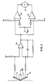
- the panel arrangement 10 comprises two solar panels 20 and 21 mounted on the carriage equally off-set from the plane of the surface of the window 11.
- the panels 20 and 21 are electrically connected to a comparator 24 which responds to differences in the currents generated by the solar cells when they convert solar energy.
- the difference in currents exceeds a value corresponding to a voltage D/2 as compared to a reference voltage
- the output of the comparator 24 is fed to bias parallel coupled amplifiers 25 and 26, also supplied with the reference voltage. This causes a supply current to flow in a drive motor 27 in one or other direction according to the polarity of the bias applied to the amplifiers.
- the drive motor will run forwards or backwards according to the direction of the supply current until the bias returns to equal the reference voltage as the carriage is moved by the motor. This is when the panels 20 and 21 have moved until they receive substantially the same amount of solar energy.
- the circuit is arranged so that the motor is only energised when the solar energy converted by the panels 20 and 21 is significantly unequal. In this way the motor is only energised say every five minutes.
- a timer circuit may be provided to constrain, or prevent, the motor being energised in intervals of less than five minutes. This has the effect of conserving the electrical energy required to move the solar panels and reduces the overall efficiency of the solar energy conversion only marginally in practice.
- the solar panel arrangement is formed with two arrays of cells in two panels which are angularly off-set slightly, say 1 0 or 2 0 , to one another and at either side of a mean optimum orientation.
- the two panels are positioned side by side facing the direction of the sun and, in the mean optimum orientation, each panel is off-set from its own optimum orientation by, say, 1 / 2 0 or 1 0 respectively.
- the output of each panel that is the solar energy converted to electrical power, is sensed and used to provide a control signal to initiate and control the operation of the drive motor.
- the small reduction in efficiency caused by off-setting the solar panels is compensated for in practice by there being no need to provide auxiliary solar panels, or other radiation sensors.
- the unit may be arranged to be generally stationary except during the hours of say 9 a.m. to 3 p.m.
- movement of panels to follow the movement of the sun during a central part of each day is sufficient to significantly increase the overall conversion of solar energy, as compared to using normal permanently fixed or stationary panels.
- the motor is inhibited so as not to be operative before, say, 9 a.m. and after 3 p.m.
- the circuit is provided with a time-of-day clock to provide suitable control signals for the motor and to cause the motor to move the carriage from a 3 p.m. position to a 9 a.m. position during the night.
- the clock may be provided with and selectable different settings as may be required for generally different conditions applicable between seasonal variations of the relative movement of the sun.
Landscapes
- Engineering & Computer Science (AREA)
- Life Sciences & Earth Sciences (AREA)
- Sustainable Development (AREA)
- General Engineering & Computer Science (AREA)
- Combustion & Propulsion (AREA)
- Sustainable Energy (AREA)
- Thermal Sciences (AREA)
- Chemical & Material Sciences (AREA)
- Physics & Mathematics (AREA)
- Mechanical Engineering (AREA)
- Photovoltaic Devices (AREA)
- Indicating Measured Values (AREA)
- Luminescent Compositions (AREA)
- Circuit Arrangements For Discharge Lamps (AREA)
- Eye Examination Apparatus (AREA)
- Blinds (AREA)
Claims (4)
- Solarpaneeleinheit mit einem bewegbaren Solarpaneelanordnungstragewagen (12) und einem Antriebsmotor (27) zum Bewegen des Wagens, derart, daß die Paneelanordnung (10) relativ zum Sonnenlicht in optimalen Ausrichtungen zur Aufnahme von Sonnenenergie ausgerichtet wird, dadurch gekennzeichnet, daß die Paneelanordnung (10) erste und zweite Hauptpaneele (20, 21) zur Umwandlung von Sonnenenergie in elektrischen Strom zum Aufladen oder zum Aufrechterhalten einer Ladung in einem Batteriesatz aufweist, wobei die ersten und zweiten Hauptpaneele winkelmäßig leicht zueinander und zu einer zentralen durchschnittlichen Optimalausrichtung der Paneelanordnung - versetzt sind, mit einer Vorrichtung (24) zum Erfassen der Intensität der Sonnenenergie, die durch die ersten und zweiten Hauptpaneele in jeweilige erste und zweite konvertierte Energien konvertiert wird, und zum Steuern des Betriebs des Motors (27), wenn es eine steigende Energiedifferenz zwischen den ersten und zweiten konvertierten Energien gibt, die ein vorbestimmtes Größenordnungsniveau übersteigt, das ausreicht, um die Paneelanordnung (10) zur optimalen Ausrichtung zu bewegen, wenn sich die Sonne relativ zu der Einheit bewegt.
- Einheit nach Anspruch 1, dadurch gekennzeichnet, daß der Wagen (12) um eine Achse schwenkbar angeordnet und der Motor derart angebracht ist, daß er den Wagen um die Achse bewegt, die im Betrieb im wesentlichen senkrecht zu dem Radius des Bogens der täglichen Bewegungen der Sonne positioniert ist.
- Einheit nach Anspruch 1 oder 2, gekennzeichnet durch eine Vorrichtung, die bewirkt, daß der Motor den Wagen intermittierend in Intervallen von wenigen Minuten oder länger bewegt.
- Solarleuchte mit einem Gehäuse, gekennzeichnet durch eine Solarpaneeleinheit nach einem der Ansprüche 1 bis 3.
Applications Claiming Priority (3)
| Application Number | Priority Date | Filing Date | Title |
|---|---|---|---|
| GB9123342 | 1991-11-04 | ||
| GB919123342A GB9123342D0 (en) | 1991-11-04 | 1991-11-04 | Solar lamp |
| PCT/GB1992/002038 WO1993009378A1 (en) | 1991-11-04 | 1992-11-04 | Solar panel unit and solar lamp including same |
Publications (2)
| Publication Number | Publication Date |
|---|---|
| EP0611432A1 EP0611432A1 (de) | 1994-08-24 |
| EP0611432B1 true EP0611432B1 (de) | 1998-01-21 |
Family
ID=10704008
Family Applications (1)
| Application Number | Title | Priority Date | Filing Date |
|---|---|---|---|
| EP92922625A Expired - Lifetime EP0611432B1 (de) | 1991-11-04 | 1992-11-04 | Solarpaneeleinheit und mit dieser versehene solarleuchte |
Country Status (8)
| Country | Link |
|---|---|
| US (1) | US5467257A (de) |
| EP (1) | EP0611432B1 (de) |
| JP (1) | JPH07507166A (de) |
| AT (1) | ATE162605T1 (de) |
| AU (1) | AU2883092A (de) |
| DE (1) | DE69224203T2 (de) |
| GB (1) | GB9123342D0 (de) |
| WO (1) | WO1993009378A1 (de) |
Families Citing this family (5)
| Publication number | Priority date | Publication date | Assignee | Title |
|---|---|---|---|---|
| US5957564A (en) * | 1996-03-26 | 1999-09-28 | Dana G. Bruce | Low power lighting display |
| DE29607497U1 (de) * | 1996-04-25 | 1996-07-18 | Vincent-Sooben, Renate, 59846 Sundern | Gartenleuchte |
| US6273015B1 (en) * | 1998-02-26 | 2001-08-14 | Maruta Electric Boatworks Llc | Stabilized electric watercraft for high speed cruising, diving and sailing |
| US7249863B2 (en) * | 2003-04-28 | 2007-07-31 | Ballarini Noelle L | Solar-powered lighting system |
| US20090211624A1 (en) * | 2008-02-26 | 2009-08-27 | Genova Michael C | Solar powered spa and hot tub down light sconce |
Family Cites Families (8)
| Publication number | Priority date | Publication date | Assignee | Title |
|---|---|---|---|---|
| JPS5623786A (en) * | 1979-08-02 | 1981-03-06 | Nec Corp | Solar battery type power generating equipment |
| DE3047724A1 (de) * | 1980-12-18 | 1982-07-15 | Fa. Paul Weiß, 8500 Nürnberg | Nachfuehrvorrichtung zur sonnenstandabhaengigen ausrichtung von sonnenenergiesammlern |
| FR2516204A1 (fr) * | 1981-11-06 | 1983-05-13 | Lampes Sa | Borne autonome d'eclairage |
| JPS6042555A (ja) * | 1983-03-28 | 1985-03-06 | Hazama Gumi Ltd | 太陽光線追従装置付き太陽熱集熱装置 |
| JPS62236009A (ja) * | 1986-04-08 | 1987-10-16 | Fujita Corp | 太陽追尾装置 |
| US5055984A (en) * | 1989-08-11 | 1991-10-08 | The Brinkmann Corporation | Solar rechargeable light |
| US4977488A (en) * | 1990-03-14 | 1990-12-11 | Australux North America Ltd. | Solar powered outdoor recreational light with positionable solar panel |
| DE9006449U1 (de) * | 1990-06-08 | 1990-09-20 | Knobel, Rolf M., Dr., 8263 Burghausen | Photovoltaische Nachführeinrichtung |
-
1991
- 1991-11-04 GB GB919123342A patent/GB9123342D0/en active Pending
-
1992
- 1992-11-04 WO PCT/GB1992/002038 patent/WO1993009378A1/en not_active Ceased
- 1992-11-04 AT AT92922625T patent/ATE162605T1/de not_active IP Right Cessation
- 1992-11-04 EP EP92922625A patent/EP0611432B1/de not_active Expired - Lifetime
- 1992-11-04 US US08/232,225 patent/US5467257A/en not_active Expired - Fee Related
- 1992-11-04 JP JP5507981A patent/JPH07507166A/ja active Pending
- 1992-11-04 AU AU28830/92A patent/AU2883092A/en not_active Abandoned
- 1992-11-04 DE DE69224203T patent/DE69224203T2/de not_active Expired - Fee Related
Also Published As
| Publication number | Publication date |
|---|---|
| DE69224203D1 (de) | 1998-02-26 |
| JPH07507166A (ja) | 1995-08-03 |
| DE69224203T2 (de) | 1998-08-27 |
| AU2883092A (en) | 1993-06-07 |
| ATE162605T1 (de) | 1998-02-15 |
| GB9123342D0 (en) | 1991-12-18 |
| EP0611432A1 (de) | 1994-08-24 |
| WO1993009378A1 (en) | 1993-05-13 |
| US5467257A (en) | 1995-11-14 |
Similar Documents
| Publication | Publication Date | Title |
|---|---|---|
| EP0849524B1 (de) | Pfosten mit Solarzellen | |
| US4620771A (en) | Combined solar tracking reflector and photovoltaic panel | |
| CA1108232A (en) | Device for converting solar energy | |
| CA2435992A1 (en) | Solar lighting apparatus of the sun tracking type | |
| WO2007062537A3 (de) | Solaranlage sowie verfahren zum betrieb | |
| WO1992016087A3 (en) | Solar powered lamp utilizing cold cathode fluorescent illumination and method of facilitating same | |
| ATE203081T1 (de) | Markise mit beleuchtungsmitteln | |
| EP0611432B1 (de) | Solarpaneeleinheit und mit dieser versehene solarleuchte | |
| JPS6478237A (en) | Dimming transmission body | |
| JPH085366A (ja) | 太陽自動追跡装置 | |
| WO2002025031A1 (fr) | Dispositif d'eclairage equipe d'un systeme de poursuite du soleil | |
| JPH06181003A (ja) | ソーラ庭園灯 | |
| US6660929B2 (en) | Electrical power module and system | |
| CN111585508A (zh) | 一种低成本太阳能发电跟踪系统与方法 | |
| US4796370A (en) | Numerical display module | |
| CN216131870U (zh) | 用于地下空间的灯光调节机构 | |
| CN212063901U (zh) | 一种用于光伏板智能监控装置 | |
| CN213847859U (zh) | 一种具有反光结构的光伏农业大棚 | |
| CN203812097U (zh) | 一种单轴太阳能光伏追日装置 | |
| US20230042945A1 (en) | Decoupling of a perovskite solar cell in darkness | |
| CN2205525Y (zh) | 太阳能集能器自动跟踪装置 | |
| KR20030042653A (ko) | 태양 추적 방식의 태양광 충전 장치 및 그를 이용한 가로등 | |
| KR200149016Y1 (ko) | 자체 전원 가로등 | |
| CN111786627A (zh) | 一种基于光感控制的追光式光伏发电装置 | |
| CN217875629U (zh) | 太阳能路灯 |
Legal Events
| Date | Code | Title | Description |
|---|---|---|---|
| PUAI | Public reference made under article 153(3) epc to a published international application that has entered the european phase |
Free format text: ORIGINAL CODE: 0009012 |
|
| 17P | Request for examination filed |
Effective date: 19940524 |
|
| AK | Designated contracting states |
Kind code of ref document: A1 Designated state(s): AT BE CH DE DK ES FR GB GR IE IT LI LU MC NL SE |
|
| 17Q | First examination report despatched |
Effective date: 19950410 |
|
| GRAG | Despatch of communication of intention to grant |
Free format text: ORIGINAL CODE: EPIDOS AGRA |
|
| GRAH | Despatch of communication of intention to grant a patent |
Free format text: ORIGINAL CODE: EPIDOS IGRA |
|
| GRAH | Despatch of communication of intention to grant a patent |
Free format text: ORIGINAL CODE: EPIDOS IGRA |
|
| GRAA | (expected) grant |
Free format text: ORIGINAL CODE: 0009210 |
|
| AK | Designated contracting states |
Kind code of ref document: B1 Designated state(s): AT BE CH DE DK ES FR GB GR IE IT LI LU MC NL SE |
|
| PG25 | Lapsed in a contracting state [announced via postgrant information from national office to epo] |
Ref country code: LI Free format text: LAPSE BECAUSE OF FAILURE TO SUBMIT A TRANSLATION OF THE DESCRIPTION OR TO PAY THE FEE WITHIN THE PRESCRIBED TIME-LIMIT Effective date: 19980121 Ref country code: IT Free format text: LAPSE BECAUSE OF FAILURE TO SUBMIT A TRANSLATION OF THE DESCRIPTION OR TO PAY THE FEE WITHIN THE PRESCRIBED TIME-LIMIT;WARNING: LAPSES OF ITALIAN PATENTS WITH EFFECTIVE DATE BEFORE 2007 MAY HAVE OCCURRED AT ANY TIME BEFORE 2007. THE CORRECT EFFECTIVE DATE MAY BE DIFFERENT FROM THE ONE RECORDED. Effective date: 19980121 Ref country code: GR Free format text: LAPSE BECAUSE OF NON-PAYMENT OF DUE FEES Effective date: 19980121 Ref country code: FR Free format text: LAPSE BECAUSE OF FAILURE TO SUBMIT A TRANSLATION OF THE DESCRIPTION OR TO PAY THE FEE WITHIN THE PRESCRIBED TIME-LIMIT Effective date: 19980121 Ref country code: ES Free format text: THE PATENT HAS BEEN ANNULLED BY A DECISION OF A NATIONAL AUTHORITY Effective date: 19980121 Ref country code: CH Free format text: LAPSE BECAUSE OF FAILURE TO SUBMIT A TRANSLATION OF THE DESCRIPTION OR TO PAY THE FEE WITHIN THE PRESCRIBED TIME-LIMIT Effective date: 19980121 Ref country code: BE Free format text: LAPSE BECAUSE OF FAILURE TO SUBMIT A TRANSLATION OF THE DESCRIPTION OR TO PAY THE FEE WITHIN THE PRESCRIBED TIME-LIMIT Effective date: 19980121 Ref country code: AT Free format text: LAPSE BECAUSE OF FAILURE TO SUBMIT A TRANSLATION OF THE DESCRIPTION OR TO PAY THE FEE WITHIN THE PRESCRIBED TIME-LIMIT Effective date: 19980121 |
|
| REF | Corresponds to: |
Ref document number: 162605 Country of ref document: AT Date of ref document: 19980215 Kind code of ref document: T |
|
| REG | Reference to a national code |
Ref country code: CH Ref legal event code: EP |
|
| REF | Corresponds to: |
Ref document number: 69224203 Country of ref document: DE Date of ref document: 19980226 |
|
| PG25 | Lapsed in a contracting state [announced via postgrant information from national office to epo] |
Ref country code: SE Free format text: LAPSE BECAUSE OF FAILURE TO SUBMIT A TRANSLATION OF THE DESCRIPTION OR TO PAY THE FEE WITHIN THE PRESCRIBED TIME-LIMIT Effective date: 19980421 Ref country code: DK Free format text: LAPSE BECAUSE OF FAILURE TO SUBMIT A TRANSLATION OF THE DESCRIPTION OR TO PAY THE FEE WITHIN THE PRESCRIBED TIME-LIMIT Effective date: 19980421 |
|
| REG | Reference to a national code |
Ref country code: IE Ref legal event code: FG4D Free format text: 78508 |
|
| EN | Fr: translation not filed | ||
| REG | Reference to a national code |
Ref country code: CH Ref legal event code: PL |
|
| PG25 | Lapsed in a contracting state [announced via postgrant information from national office to epo] |
Ref country code: LU Free format text: LAPSE BECAUSE OF NON-PAYMENT OF DUE FEES Effective date: 19981104 Ref country code: IE Free format text: LAPSE BECAUSE OF NON-PAYMENT OF DUE FEES Effective date: 19981104 |
|
| PLBE | No opposition filed within time limit |
Free format text: ORIGINAL CODE: 0009261 |
|
| STAA | Information on the status of an ep patent application or granted ep patent |
Free format text: STATUS: NO OPPOSITION FILED WITHIN TIME LIMIT |
|
| 26N | No opposition filed | ||
| PG25 | Lapsed in a contracting state [announced via postgrant information from national office to epo] |
Ref country code: MC Free format text: LAPSE BECAUSE OF NON-PAYMENT OF DUE FEES Effective date: 19990531 |
|
| REG | Reference to a national code |
Ref country code: GB Ref legal event code: IF02 |
|
| PGFP | Annual fee paid to national office [announced via postgrant information from national office to epo] |
Ref country code: DE Payment date: 20041028 Year of fee payment: 13 |
|
| PGFP | Annual fee paid to national office [announced via postgrant information from national office to epo] |
Ref country code: NL Payment date: 20041103 Year of fee payment: 13 |
|
| PGFP | Annual fee paid to national office [announced via postgrant information from national office to epo] |
Ref country code: GB Payment date: 20041104 Year of fee payment: 13 |
|
| PG25 | Lapsed in a contracting state [announced via postgrant information from national office to epo] |
Ref country code: GB Free format text: LAPSE BECAUSE OF NON-PAYMENT OF DUE FEES Effective date: 20051104 |
|
| PG25 | Lapsed in a contracting state [announced via postgrant information from national office to epo] |
Ref country code: NL Free format text: LAPSE BECAUSE OF NON-PAYMENT OF DUE FEES Effective date: 20060601 Ref country code: DE Free format text: LAPSE BECAUSE OF NON-PAYMENT OF DUE FEES Effective date: 20060601 |
|
| GBPC | Gb: european patent ceased through non-payment of renewal fee |
Effective date: 20051104 |
|
| NLV4 | Nl: lapsed or anulled due to non-payment of the annual fee |
Effective date: 20060601 |