EP0611404B1 - Shaped fabric products and methods of making same - Google Patents
Shaped fabric products and methods of making same Download PDFInfo
- Publication number
- EP0611404B1 EP0611404B1 EP92922758A EP92922758A EP0611404B1 EP 0611404 B1 EP0611404 B1 EP 0611404B1 EP 92922758 A EP92922758 A EP 92922758A EP 92922758 A EP92922758 A EP 92922758A EP 0611404 B1 EP0611404 B1 EP 0611404B1
- Authority
- EP
- European Patent Office
- Prior art keywords
- sleeve
- filamentary
- fill
- warp
- product
- Prior art date
- Legal status (The legal status is an assumption and is not a legal conclusion. Google has not performed a legal analysis and makes no representation as to the accuracy of the status listed.)
- Expired - Lifetime
Links
- 239000004744 fabric Substances 0.000 title claims abstract description 46
- 238000000034 method Methods 0.000 title abstract description 19
- 238000005299 abrasion Methods 0.000 claims description 17
- 229920000728 polyester Polymers 0.000 claims description 6
- 229920005992 thermoplastic resin Polymers 0.000 claims description 6
- 238000010276 construction Methods 0.000 claims description 4
- 239000004952 Polyamide Substances 0.000 claims description 3
- 229920002647 polyamide Polymers 0.000 claims description 3
- 239000000758 substrate Substances 0.000 abstract description 15
- 239000000463 material Substances 0.000 description 23
- 238000012360 testing method Methods 0.000 description 13
- 230000001681 protective effect Effects 0.000 description 5
- 239000002759 woven fabric Substances 0.000 description 5
- 239000002184 metal Substances 0.000 description 4
- 229910052751 metal Inorganic materials 0.000 description 4
- 230000002787 reinforcement Effects 0.000 description 4
- 238000004519 manufacturing process Methods 0.000 description 3
- 150000002739 metals Chemical class 0.000 description 3
- 239000004033 plastic Substances 0.000 description 3
- 229920003023 plastic Polymers 0.000 description 3
- 230000000712 assembly Effects 0.000 description 2
- 238000000429 assembly Methods 0.000 description 2
- 238000004132 cross linking Methods 0.000 description 2
- 229920006351 engineering plastic Polymers 0.000 description 2
- -1 polyethylene Polymers 0.000 description 2
- 230000035882 stress Effects 0.000 description 2
- 239000000126 substance Substances 0.000 description 2
- 239000012209 synthetic fiber Substances 0.000 description 2
- 229920002994 synthetic fiber Polymers 0.000 description 2
- 238000009941 weaving Methods 0.000 description 2
- 239000004698 Polyethylene Substances 0.000 description 1
- 230000009286 beneficial effect Effects 0.000 description 1
- 230000015572 biosynthetic process Effects 0.000 description 1
- 239000003153 chemical reaction reagent Substances 0.000 description 1
- 230000000052 comparative effect Effects 0.000 description 1
- 238000013461 design Methods 0.000 description 1
- 230000000694 effects Effects 0.000 description 1
- 238000011156 evaluation Methods 0.000 description 1
- 230000006355 external stress Effects 0.000 description 1
- 239000000835 fiber Substances 0.000 description 1
- 229920002313 fluoropolymer Polymers 0.000 description 1
- 239000006261 foam material Substances 0.000 description 1
- 230000009477 glass transition Effects 0.000 description 1
- 238000010438 heat treatment Methods 0.000 description 1
- 238000010348 incorporation Methods 0.000 description 1
- 229910052500 inorganic mineral Inorganic materials 0.000 description 1
- 230000001678 irradiating effect Effects 0.000 description 1
- 239000011707 mineral Substances 0.000 description 1
- 239000000203 mixture Substances 0.000 description 1
- 229920000573 polyethylene Polymers 0.000 description 1
- 239000002952 polymeric resin Substances 0.000 description 1
- 229920000098 polyolefin Polymers 0.000 description 1
- 238000012545 processing Methods 0.000 description 1
- 229920005989 resin Polymers 0.000 description 1
- 239000011347 resin Substances 0.000 description 1
- 239000005060 rubber Substances 0.000 description 1
- 238000009958 sewing Methods 0.000 description 1
- 239000011343 solid material Substances 0.000 description 1
- 229910001220 stainless steel Inorganic materials 0.000 description 1
- 239000010935 stainless steel Substances 0.000 description 1
Images
Classifications
-
- F—MECHANICAL ENGINEERING; LIGHTING; HEATING; WEAPONS; BLASTING
- F16—ENGINEERING ELEMENTS AND UNITS; GENERAL MEASURES FOR PRODUCING AND MAINTAINING EFFECTIVE FUNCTIONING OF MACHINES OR INSTALLATIONS; THERMAL INSULATION IN GENERAL
- F16L—PIPES; JOINTS OR FITTINGS FOR PIPES; SUPPORTS FOR PIPES, CABLES OR PROTECTIVE TUBING; MEANS FOR THERMAL INSULATION IN GENERAL
- F16L57/00—Protection of pipes or objects of similar shape against external or internal damage or wear
- F16L57/06—Protection of pipes or objects of similar shape against external or internal damage or wear against wear
-
- D—TEXTILES; PAPER
- D03—WEAVING
- D03D—WOVEN FABRICS; METHODS OF WEAVING; LOOMS
- D03D1/00—Woven fabrics designed to make specified articles
- D03D1/0035—Protective fabrics
- D03D1/0043—Protective fabrics for elongated members, i.e. sleeves
-
- D—TEXTILES; PAPER
- D03—WEAVING
- D03D—WOVEN FABRICS; METHODS OF WEAVING; LOOMS
- D03D13/00—Woven fabrics characterised by the special disposition of the warp or weft threads, e.g. with curved weft threads, with discontinuous warp threads, with diagonal warp or weft
- D03D13/002—With diagonal warps or wefts
-
- D—TEXTILES; PAPER
- D03—WEAVING
- D03D—WOVEN FABRICS; METHODS OF WEAVING; LOOMS
- D03D3/00—Woven fabrics characterised by their shape
- D03D3/02—Tubular fabrics
-
- D—TEXTILES; PAPER
- D06—TREATMENT OF TEXTILES OR THE LIKE; LAUNDERING; FLEXIBLE MATERIALS NOT OTHERWISE PROVIDED FOR
- D06C—FINISHING, DRESSING, TENTERING OR STRETCHING TEXTILE FABRICS
- D06C5/00—Shaping or stretching of tubular fabrics upon cores or internal frames
- D06C5/005—Shaping or stretching of tubular fabrics upon cores or internal frames of articles, e.g. stockings
-
- D—TEXTILES; PAPER
- D06—TREATMENT OF TEXTILES OR THE LIKE; LAUNDERING; FLEXIBLE MATERIALS NOT OTHERWISE PROVIDED FOR
- D06C—FINISHING, DRESSING, TENTERING OR STRETCHING TEXTILE FABRICS
- D06C7/00—Heating or cooling textile fabrics
- D06C7/02—Setting
-
- F—MECHANICAL ENGINEERING; LIGHTING; HEATING; WEAPONS; BLASTING
- F16—ENGINEERING ELEMENTS AND UNITS; GENERAL MEASURES FOR PRODUCING AND MAINTAINING EFFECTIVE FUNCTIONING OF MACHINES OR INSTALLATIONS; THERMAL INSULATION IN GENERAL
- F16L—PIPES; JOINTS OR FITTINGS FOR PIPES; SUPPORTS FOR PIPES, CABLES OR PROTECTIVE TUBING; MEANS FOR THERMAL INSULATION IN GENERAL
- F16L57/00—Protection of pipes or objects of similar shape against external or internal damage or wear
- F16L57/02—Protection of pipes or objects of similar shape against external or internal damage or wear against cracking or buckling
-
- H—ELECTRICITY
- H02—GENERATION; CONVERSION OR DISTRIBUTION OF ELECTRIC POWER
- H02G—INSTALLATION OF ELECTRIC CABLES OR LINES, OR OF COMBINED OPTICAL AND ELECTRIC CABLES OR LINES
- H02G3/00—Installations of electric cables or lines or protective tubing therefor in or on buildings, equivalent structures or vehicles
- H02G3/02—Details
- H02G3/04—Protective tubing or conduits, e.g. cable ladders or cable troughs
- H02G3/0462—Tubings, i.e. having a closed section
- H02G3/0481—Tubings, i.e. having a closed section with a circular cross-section
-
- Y—GENERAL TAGGING OF NEW TECHNOLOGICAL DEVELOPMENTS; GENERAL TAGGING OF CROSS-SECTIONAL TECHNOLOGIES SPANNING OVER SEVERAL SECTIONS OF THE IPC; TECHNICAL SUBJECTS COVERED BY FORMER USPC CROSS-REFERENCE ART COLLECTIONS [XRACs] AND DIGESTS
- Y10—TECHNICAL SUBJECTS COVERED BY FORMER USPC
- Y10S—TECHNICAL SUBJECTS COVERED BY FORMER USPC CROSS-REFERENCE ART COLLECTIONS [XRACs] AND DIGESTS
- Y10S139/00—Textiles: weaving
- Y10S139/01—Bias fabric digest
-
- Y—GENERAL TAGGING OF NEW TECHNOLOGICAL DEVELOPMENTS; GENERAL TAGGING OF CROSS-SECTIONAL TECHNOLOGIES SPANNING OVER SEVERAL SECTIONS OF THE IPC; TECHNICAL SUBJECTS COVERED BY FORMER USPC CROSS-REFERENCE ART COLLECTIONS [XRACs] AND DIGESTS
- Y10—TECHNICAL SUBJECTS COVERED BY FORMER USPC
- Y10T—TECHNICAL SUBJECTS COVERED BY FORMER US CLASSIFICATION
- Y10T156/00—Adhesive bonding and miscellaneous chemical manufacture
- Y10T156/10—Methods of surface bonding and/or assembly therefor
- Y10T156/1002—Methods of surface bonding and/or assembly therefor with permanent bending or reshaping or surface deformation of self sustaining lamina
-
- Y—GENERAL TAGGING OF NEW TECHNOLOGICAL DEVELOPMENTS; GENERAL TAGGING OF CROSS-SECTIONAL TECHNOLOGIES SPANNING OVER SEVERAL SECTIONS OF THE IPC; TECHNICAL SUBJECTS COVERED BY FORMER USPC CROSS-REFERENCE ART COLLECTIONS [XRACs] AND DIGESTS
- Y10—TECHNICAL SUBJECTS COVERED BY FORMER USPC
- Y10T—TECHNICAL SUBJECTS COVERED BY FORMER US CLASSIFICATION
- Y10T428/00—Stock material or miscellaneous articles
- Y10T428/13—Hollow or container type article [e.g., tube, vase, etc.]
- Y10T428/1328—Shrinkable or shrunk [e.g., due to heat, solvent, volatile agent, restraint removal, etc.]
- Y10T428/1331—Single layer [continuous layer]
-
- Y—GENERAL TAGGING OF NEW TECHNOLOGICAL DEVELOPMENTS; GENERAL TAGGING OF CROSS-SECTIONAL TECHNOLOGIES SPANNING OVER SEVERAL SECTIONS OF THE IPC; TECHNICAL SUBJECTS COVERED BY FORMER USPC CROSS-REFERENCE ART COLLECTIONS [XRACs] AND DIGESTS
- Y10—TECHNICAL SUBJECTS COVERED BY FORMER USPC
- Y10T—TECHNICAL SUBJECTS COVERED BY FORMER US CLASSIFICATION
- Y10T428/00—Stock material or miscellaneous articles
- Y10T428/13—Hollow or container type article [e.g., tube, vase, etc.]
- Y10T428/1352—Polymer or resin containing [i.e., natural or synthetic]
- Y10T428/1362—Textile, fabric, cloth, or pile containing [e.g., web, net, woven, knitted, mesh, nonwoven, matted, etc.]
Definitions
- the present invention is directed to tubular products, and more particularly to tubular fabrics which are particularly well adapted for bundling and protecting elongated articles, such as wires, cables, hoses and conduits.
- Evans et al illustrates the warp elements as extending along the length of the hose in a direction substantially parallel to the axis of the hose.
- US Patent No 4,652,263 - Herwick et al is directed to woven fabric tubes especially adapted for use as prostheses in biomedical applications.
- Herwick et al note that such woven fabric tubes are preferably capable of returning their original shape after being stretched, compressed or bent.
- Herwick et al also note that such tubular products should also be resistant to kinking or radial collapse.
- Elasticity is imparted to the tubes of Herwick et al by providing the woven tubular products with axially-orientated warp threads forming loops extending radially outward between circumferential fill threads. The loops are set to return to the loop configuration upon release of tension applied axially to the tube.
- tubular fabric is to reinforce a rubber/plastics hose material is also known from GB-A-2,045,383A, which discloses the use of a pre-twisting treatment to reduce torsion in the final hose product.
- GB-A-2,117,418A discloses a multi-axial fabric suitable for plastics reinforcement and incorporating additional yarns at an angle of 45 degrees to the warp and weft (this document also discloses the features of the preamble of claim 1).
- US-A-1,947,924 discloses apparatus for enclosing a core such as wire or cable in a woven sleeve, the latter comprising numerous warp yarns, extending along and around the core, together with a relatively small number of weft yarns extending around the core. None of these three documents addresses the problem of forming an essentially self-supporting kink-resistant fabric tube without any additional reinforcement.
- Applicants have recognized a need for a sleeve which is at once shape-retaining, kink-resistant and flexible. Furthermore, Applicants have recognized the failure of the prior art to provide methods for manufacturing woven tubular products which possess these characteristics.
- the present invention provides a flexible, abrasion and kink-resistant sleeve for protection of elongated articles, such as cables, conduits, wires and hoses according to claim 1.
- Claims 2-5 give advantageous embodiments of the sleeve according to claim 1.
- the shaped fabric products are preferably elongate tubular products having a longitudinal dimension which is substantially greater than the width, diameter or girth of the product.
- the shaped fabric products include a wall portion comprising a filament resiliently set in a spiral configuration with respect to the longitudinal axis of the shaped product. Applicants have found that tubular products comprising fabrics, and preferably woven fabrics, having such spirally set filaments generally possess excellent flexibility and exceptional kink- and abrasion-resistance.
- the wall portion of the tubular product also comprises a filament in the form of circumferential hoops substantially conforming in shape and size to the cross-sectional configuration of the shaped product.
- the circumferential hoops are substantially circular hoops having a diameter equal to about the diameter of the cylinder.
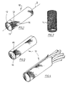
- Fig. 1 is a perspective view of a woven tubular product according to a first embodiment of the present invention.
- Fig. 2 is a plan view of a woven tubular product according to a first embodiment of the present invention.
- Fig. 3 is a perspective view of a woven tubular product which is radially discontinuous according to a second embodiment of the present invention.
- Fig. 4 is a perspective view of a radially discontinuous woven tubular product of the present invention encasing an elongate substrate.
- the present invention is directed to a flexible abrasion and kink-resistant sleeve. It is contemplated that the sleeve comprises woven products.
- the woven products comprise fill and warp threads interlaced according to any one of the well-known weave patterns. In general, however, applicants have found that a twill pattern, and preferably a 2-2 twill pattern, produces acceptable results.
- the wall portion of the sleeves are characterized by an open construction. That is that the filamentary materials comprising the wall portion of the shaped fabric are relatively loosely interlaced. In this way, the shaped fabric products of the present invention breathe and prevent entrapment of moisture.
- the present shaped fabric products are particularly well adapted for protecting and/or covering substrates, especially elongate substrates.
- the particular shape of the present fabric will thus typically depend upon the shape of the substrate being covered or protected.
- the shaped fabric product will provide a wall portion for covering the substrate and a chamber or open area internal to the wall portion for containing at least a portion of the substrate.
- the shaped fabric products will preferably possess a hollow portion defined by a wall portion having a shape corresponding generally to the shape of the substrate to be protected, thereby providing a chamber or cavity for accepting the substrate. While all such shapes are within the scope of the present invention, it is contemplated that the shaped fabrics of the present invention will be in tubular form.
- tubular refers to an elongate article having an internal chamber running substantially along the length thereof.
- the tubular products of the present invention will have a circular cross-sectional configuration.
- the shaped fabric products comprise filaments in the wall portion thereof resiliently set in a spiral configuration relative to the longitudinal axis of the shaped fabric.
- the fabric product includes filaments resiliently set in a spiral pattern with respect to the axis of the tube.
- resilient set refers to the incorporation of a permanent set or a bias in a resilient filamentary material.
- the pitch of the resiliently set spiral filaments may vary within the scope of claim 1, depending upon such factors as the particular filamentary material being used, the cost of the product and the degree of flexibility and kink-resistance which is desired.
- the resiliently set spiral filaments have a pitch of from about 0.2 to about 0.3 turns per 25.4mm (inch) of length.
- tubular fabric products, and especially woven tubular products having a circular cross-section and an inner diameter of from about 9.5mm (3/16 inch) to about 102mm (4 inches) possess high levels of both flexibility and kink-resistance when the spiral filaments have a pitch within the range described herein.
- Applicants have found that such tubular products possess an unexpectedly high degree of abrasion resistance.
- the sleeve includes a wall portion comprising filaments resiliently set in a spiral configuration relative to the longitudinal axis of the shaped fabric such that the tubular products has an abrasion resistance of at least about 25,000 cycles and even more preferably of from about 30,000 to about 60,000 cycles of the ARP test.
- the ARP test refers to the abrasion test outlined hereinafter in the Example section of the present specification.
- the wall portion of the shaped fabric product also comprises resiliently set circumferential hoops substantially conforming in shape and size to the cross-sectional configuration of the shaped product.
- cross-sectional configuration refers to the configuration of a shaped product in a plane which is substantially normal with respect to the longitudinal axis of the product.
- the wall portion of cylindrically shaped tubular fabrics preferably includes resiliently set circular filaments forming hoops having approximately the diameter of the cylinder.
- the shaped product is a woven product in which a substantial portion of the fill threads, and even more preferably substantially all of the fill threads, are resiliently set in the form of circumferential hoops and wherein a substantial portion of the warp ends, and even more preferably substantially all of the warp ends, are resiliently set in a spiral configuration with respect to the longitudinal axis of the shaped product.
- filamentary materials of construction are capable of being provided with a resilient set.
- a large number of materials are adaptable for use in forming the resiliently settable filaments hereof.
- many structural metals and engineering plastics will assume a permanent set when stressed above their elastic limit at room temperature.
- the filamentary material of the present invention will be provided with a resilient set or bias by the application of heat, pressure, irradiation, chemical reagents and combinations of these.
- thermoplastic resins are polymeric materials that soften or melt at elevated temperatures, thus allowing them to be processed into shapes and products that, when cooled, recover the physical and chemical properties of the original resin.
- this class of materials generally has a good balance of high tensile properties, compressive and shear strength, as well as impact resistance.
- Exemplary thermoplastic resins are polyamides, polyesters, and polyolefins, with polyamides and polyesters being preferred.
- Filaments comprised of thermoplastic resins of the type described may be cause to take a resilient, permanent set by forming a product comprised of the plastic material to a specific geometry, for example, a circular or spiral shape, and then modifying the properties of the material. As mentioned above, this is usually accomplished by the application of heat to raise its temperature to a point either above the glass transition temperature or above the softening point. The shaped product is then cooled so as to recrystallize or "set” the filamentary material. The product thereafter has a resilient set or bias (sometimes called an "elastic memory”) in the shape in which it was formed, as is well recognized by those of ordinary skill in the art.
- a resilient set or bias sometimes called an "elastic memory
- such a set may be provided to filamentary material comprising polyethylene by irradiating the shaped product so as to cross-link the polyethylene chains.
- cross-linking may be accelerated or enhanced by the inclusion of cross-linking promoters in the polymeric material.
- the resiliently settable filaments used in the fabrics of the present invention may vary widely both as to type and dimension.
- the resiliently settable filaments may include multi-filament yarns and threads, monofilament yarns and threads or mixtures of these types of filaments, with monofilaments being preferred.
- filamentary material other than the resiliently settable material described above may be included with advantage in the shaped fabrics of the present invention.
- filaments comprised of fluorocarbon polymer resin to impart low friction characteristics to the shaped products.
- combinations of engineering plastic materials and yarns or strands or filaments comprised of metals or mineral materials may be used.
- the present fabrics may comprise, in addition to the resiliently settable filaments hereof, other natural and synthetic filaments which contribute but do not detract from the properties of the present shaped products.
- the shaped fabric product designated generally as 10, comprises a woven tubular product having a circular cross-section.
- the tubular product comprises a wall portion 11 forming a hollow chamber 12.
- the hollow chamber 12 is filled by an elongate substrate which is to be protected by the shaped fabric 10.
- Wall portion 11 of shaped product 10 comprises fill ends 13 interlaced with warp ends 14.
- Fill ends 13 are in the shape of circular hoops or bands having a diameter equivalent to about the diameter of the wall portion 11 of tubular product 10.
- Warp ends 14 are resiliently set in a spiral configuration with respect to the longitudinal axis z of tubular product 10.
- the tubular product is constructed by first providing a woven tubular product in which the fill ends lie in a plane which is substantially perpendicular to the axis of the tube and in which the warp ends lie in a plane which is substantially parallel to the axis of the tube. Numerous techniques are available for providing such a product, and all such techniques are within the scope hereof. For example, such a tubular product may be provided by first providing a rectangular sheet of woven fabric in which the fill ends are substantially parallel to the short edge of the sheet and the warp ends are substantially parallel to the long edge of the woven sheet.
- this woven rectangular sheet are then joined according to any one of several well-known techniques, such as sewing, to form a woven product which is continuous along its short edge.
- sewing any one of several well-known techniques, such as sewing
- other methods and techniques are known and available for forming woven fabrics which are continuous along their short edge.
- certain weaving equipment such as narrow fabric needle looms, are readily adapted to produce such woven products.
- the woven products can then be formed into a tubular configuration by, for example, placing the product over a cylindrical mandrel.
- tubular products using narrow fabric needle looms as indicated herein produces woven tubular products in which a single fill end is knitted to itself to form interconnected resilient hoops disposed in a plane which is substantially perpendicular to the axis of the tube.
- the methods of making the sleeve further comprise resiliently setting the warp ends of the provided tubular product in a spiral configuration relative to the axis of the tube.
- This step preferably comprises rotating a first portion of the tubular product about its longitudinal axis while preventing a second portion of the tubular product from rotating.
- the warp ends of the woven product are twisted into a spiral configuration with respect to the axis of the tube.
- the warp ends may be resiliently set according to techniques of the type described above to retain the spiral configuration.
- the fill ends 13 are also comprised of resiliently settable material, and the step of resiliently setting the warp ends in the spiral configuration will also provide the preferred step of resiliently setting the fill ends in the form of a circular hoop.
- the present invention is not limited to continuous tubular products of the type illustrated in Fig. 1.
- a second embodiment of the present invention provides tubular products which are discontinuous in the circumferential direction as illustrated in Fig. 3.
- tubular products of the present invention which are discontinuous in the circumferential direction have certain advantages, especially when the wall portion of the tubular product includes resiliently set fill ends in the form of hoops or bands.
- the discontinuity imparted to products of the type illustrated in Fig. 3 permits the tubular product to be readily opened in the circumferential direction, thereby providing easy assembly of the protective cover around the substrate to be protected.
- the resiliently set circumferential hoops provided by fill ends 13 such a tubular product will return resiliently to its relatively closed configuration, thereby providing protection to the enclosed substrate, as illustrated in Fig. 4.
- tubular products which are discontinuous in the circumferential direction may be prepared according to various techniques, and all such techniques are within the scope of the present invention.
- tubular products of the type disclosed in Fig. 3 may be prepared by providing a longitudinal cut or slit in the wall portion 12 of the tubular product, thereby producing a tubular product having adjacent longitudinal edges. While such a cut or slit will provide the advantages described above, it may also have disadvantages in some applications. For example, the simple provision of a cut or a slit longitudinally of the tube may leave a small gap or opening in the tube wall. This small gap or opening may be a disadvantage for applications which require that the enclosed substrate be completely mechanically isolated from the environment.
- the longitudinal edges 15 and 16 of the discontinuous tubular product overlap one another in the radial direction, as illustrated in Fig. 3.
- This overlap may be provided using any one of several processing techniques.
- the tubular product will be radially compressed so as to provide overlap between edges 15 and 16 and subsequently heat set in this compressed position.
- the discontinuous tubular product may be provided to a folder of well a known design and heated, preferably simultaneously heated, to provide edges 15 and 16 in a heat set, overlapped position.
- the discontinuous tubular product may be wrapped around a mandrel having a diameter smaller than the inner diameter of the discontinuous tube such than overlap of the longitudinal edges occurs. The overlapped configuration is then set into the tube, such as by the application of heat to the mandrel.
- tubular products of the present invention may be provided in a wide variety of shapes and sizes, it is generally preferred that tubular products are substantially circular in cross-section and have an inner diameter of about 6.4mm (0.25 inch) to about 102mm (4 inches). Furthermore, it is generally preferred that the warp and fill threads of the present invention are monofilaments having a diameter of from about 5 to about 15 mil with about 8 to about 10 mil being preferred.
- Shaped fabric products particularly tubular fabrics for use in casing and covering elongated substrates, according to the present invention exhibit exceptional and altogether unexpected results.
- one important characteristic of the shaped articles of the present invention is the excellent abrasion resistance thereof.
- the following examples which are set forth by way of illustration but not by way of limitation, describe the improvements in abrasion resistance which are achieved according to the present invention as compared to typical prior art products.
- abrasion tests were performed utilising established standard test criteria for the evaluation of chaff guards intended to provide from abrasion and chaffing of hose assemblies and adjacent components, as set forth by the Society of Automotive Engineers, Inc.
- each tubular fabric being tested was installed over a stainless steel mandrel, approximately 15 inches long.
- the mandrel and tubular product were restrained by suitable clamps and fittings according to the specified criteria.
- the test results were operated under ambient temperature conditions.
- An abrasive element comprising a 12.7mm (0.50 inch) precision ground drill rod (QQ-T-580) with a specific heat treatment of 60-64 HRC hardness and a surface finish of R 16 ⁇ in (0.40 ⁇ m) was applied to the outer surface of the tubular fabric with a total force of about 2.27Kg (5 pounds).
- the abrasive force was then reciprocated longitudinally across the tubular product at a rate of about 200 cycles per minute through a total stroke of about 76mm (3 inch).
- failure of the protective cover is established as a wearing through of the cover by the abrasion element. Such a failure is determined by the abrasive element contacting the metal reinforcement of the hose assembly after wear through of the fabric product, thus closing an electrical circuit which stops the tester.
- a braided tubular product having an inner diameter of about 12.7mm (0.5 inch) comprising polyester monofilament having a diameters of about 0.25mm (.010 inch) and a braid pattern of one over, one under was subject to an abrasion test according to the procedure described above.
- the tubular product was substantially circular in cross-section and had an inner diameter of about 12.7mm (0.5 inch).
- Such a product is generally available under the trade designation of EXPANDO R .
- a series of three tests of the type described above were carried out. The results of this test are described in connection with Table 1 below. Table 1 Run # Cycles to Failure 1 13,800 2 9,700 3 14,600 Avg. 12,700
- a woven tubular product according to the present invention was subject to an abrasion test according to the procedure described above.
- the woven product comprised polyester monofilament fill threads having a diameter of about 0.23mm (0.009 inch) and polyester monofilament warp threads having a diameter of about 0.25mm (0.010 inch) in a 2-2 twill pattern.
- the tubular product was substantially circular in cross-section and had an inner diameter of about 12.7mm (0.5 inch).
- the fill threads were all resiliently set by the application of heat in the form of a substantially circular hoop having a diameter of about 13.2mm (0.52 inch).
- the warp threads were all resiliently set by the application of heat in a spiral configuration having a pitch of about 0.2 turns per 25.4mm (inch) length.
- Table 2 Run # Cycles to Failure 1 56,500 2 50,400 3 62,600 Avg. 56,500
Landscapes
- Engineering & Computer Science (AREA)
- Textile Engineering (AREA)
- General Engineering & Computer Science (AREA)
- Mechanical Engineering (AREA)
- Structural Engineering (AREA)
- Civil Engineering (AREA)
- Architecture (AREA)
- Woven Fabrics (AREA)
- Details Of Indoor Wiring (AREA)
- Rigid Pipes And Flexible Pipes (AREA)
- Braiding, Manufacturing Of Bobbin-Net Or Lace, And Manufacturing Of Nets By Knotting (AREA)
- Protection Of Pipes Against Damage, Friction, And Corrosion (AREA)
- Flexible Shafts (AREA)
- Knitting Of Fabric (AREA)
Abstract
Description
- The present invention is directed to tubular products, and more particularly to tubular fabrics which are particularly well adapted for bundling and protecting elongated articles, such as wires, cables, hoses and conduits.
- The use of fabric sleeves for encasing cables, hoses and other elongated flexible articles is well-known in the art. Examples of such sleeving are available from the Bentley-Harris Manufacturing Company under the registered trademark EXPANDO. The EXPANDO® sleeving is lightweight and provides tough physical protection for cable assemblies, wire harnesses and the like. The open construction of this type of product is of advantage over solid material in that it breathes and prevents the entrapment of moisture. In addition, this type of sleeving maintains the bundled, elongated articles in clean, compact condition.
- While sleeving of the type employed by the EXPANDO® product has achieved significant success and possesses certain advantageous characteristics, a need for flexible, kink-resistant woven tubular products continues to exist. U.S. Patent No. 4,228,824 - Evans et al., for example, recognizes the difficultly of providing woven tubular products which resist kinking when curved or bent. Evans et al. teaches that this difficulty may be overcome by providing a hose having a reinforcement structure comprised of plied warp yarns formed of filaments of high modulus material which resists longitudinal extension of the hose. The warp elements of Evans et al. are said to have a high degree of twist in the filaments in order to provide stability to the hose wall when compressed during curving of the hose. Furthermore, Evans et al illustrates the warp elements as extending along the length of the hose in a direction substantially parallel to the axis of the hose.
- US Patent No 4,652,263 - Herwick et al is directed to woven fabric tubes especially adapted for use as prostheses in biomedical applications. Herwick et al note that such woven fabric tubes are preferably capable of returning their original shape after being stretched, compressed or bent. Herwick et al also note that such tubular products should also be resistant to kinking or radial collapse. Elasticity is imparted to the tubes of Herwick et al by providing the woven tubular products with axially-orientated warp threads forming loops extending radially outward between circumferential fill threads. The loops are set to return to the loop configuration upon release of tension applied axially to the tube.
- US Patent No 4,015,641 - Goff et al recognises the difficulty associated with providing shape retaining woven tubular products. In particular, Goff et al notes that tubular fabrics have heretofore been filled with foam material so that the product will have a cushioned, shape retaining characteristic. Goff et al suggest that a similar effect can be obtained by forming a woven tubular product using monofilament filling yarns in both layers of the fabric and alternately and intermittently weaving monofilament warp yarns between the layers to connect the two layers together.
- The use of tubular fabric is to reinforce a rubber/plastics hose material is also known from GB-A-2,045,383A, which discloses the use of a pre-twisting treatment to reduce torsion in the final hose product. GB-A-2,117,418A discloses a multi-axial fabric suitable for plastics reinforcement and incorporating additional yarns at an angle of 45 degrees to the warp and weft (this document also discloses the features of the preamble of claim 1). US-A-1,947,924 discloses apparatus for enclosing a core such as wire or cable in a woven sleeve, the latter comprising numerous warp yarns, extending along and around the core, together with a relatively small number of weft yarns extending around the core. None of these three documents addresses the problem of forming an essentially self-supporting kink-resistant fabric tube without any additional reinforcement.
- Whilst the products mentioned above may have achieved some degree of success, they also possess certain drawbacks. For example, potentially costly and somewhat unusual manufacturing techniques are required to produce the products of the type described above. Moreover, the products described in Goff et al suffer from the disadvantage of requiring the presence of structural members spanning the hollow portion of the tubular product. The presence of such structural members limits the usefulness of the tubular product for encasing elongate substrates.
- Thus, Applicants have recognized a need for a sleeve which is at once shape-retaining, kink-resistant and flexible. Furthermore, Applicants have recognized the failure of the prior art to provide methods for manufacturing woven tubular products which possess these characteristics.
- Furthermore, while the abrasion-resistance of the heretofore used protective fabric coverings has been acceptable in many applications, applicants have found that tremendous improvement in abrasion resistance is possible. Such improvement in abrasion resistance is highly desirable for obvious reasons, such as increasing the useful life of the protective fabric cover.
- Accordingly, it is an object of the present invention to provide flexible, kink-resistant fabric covers.
- It is a further object to the present invention to provide relatively low-cost protective fabric covers.
- It is yet a further object of the present invention to provide flexible, kink-resistant fabric covers with excellent abrasion resistance.
- The present invention provides a flexible, abrasion and kink-resistant sleeve for protection of elongated articles, such as cables, conduits, wires and hoses according to claim 1. Claims 2-5 give advantageous embodiments of the sleeve according to claim 1. The shaped fabric products are preferably elongate tubular products having a longitudinal dimension which is substantially greater than the width, diameter or girth of the product. According to important aspects of the present invention, the shaped fabric products include a wall portion comprising a filament resiliently set in a spiral configuration with respect to the longitudinal axis of the shaped product. Applicants have found that tubular products comprising fabrics, and preferably woven fabrics, having such spirally set filaments generally possess excellent flexibility and exceptional kink- and abrasion-resistance.
- The wall portion of the tubular product also comprises a filament in the form of circumferential hoops substantially conforming in shape and size to the cross-sectional configuration of the shaped product. For the preferred cylindrically shaped tubular products, the circumferential hoops are substantially circular hoops having a diameter equal to about the diameter of the cylinder.
- Fig. 1 is a perspective view of a woven tubular product according to a first embodiment of the present invention.
- Fig. 2 is a plan view of a woven tubular product according to a first embodiment of the present invention.
- Fig. 3 is a perspective view of a woven tubular product which is radially discontinuous according to a second embodiment of the present invention.
- Fig. 4 is a perspective view of a radially discontinuous woven tubular product of the present invention encasing an elongate substrate.
- The present invention is directed to a flexible abrasion and kink-resistant sleeve. It is contemplated that the sleeve comprises woven products. The woven products comprise fill and warp threads interlaced according to any one of the well-known weave patterns. In general, however, applicants have found that a twill pattern, and preferably a 2-2 twill pattern, produces acceptable results.
- Furthermore, the wall portion of the sleeves are characterized by an open construction. That is that the filamentary materials comprising the wall portion of the shaped fabric are relatively loosely interlaced. In this way, the shaped fabric products of the present invention breathe and prevent entrapment of moisture.
- The present shaped fabric products are particularly well adapted for protecting and/or covering substrates, especially elongate substrates. The particular shape of the present fabric will thus typically depend upon the shape of the substrate being covered or protected. In all cases, however, the shaped fabric product will provide a wall portion for covering the substrate and a chamber or open area internal to the wall portion for containing at least a portion of the substrate. Thus, the shaped fabric products will preferably possess a hollow portion defined by a wall portion having a shape corresponding generally to the shape of the substrate to be protected, thereby providing a chamber or cavity for accepting the substrate. While all such shapes are within the scope of the present invention, it is contemplated that the shaped fabrics of the present invention will be in tubular form. As used herein, the term "tubular" refers to an elongate article having an internal chamber running substantially along the length thereof. The tubular products of the present invention will have a circular cross-sectional configuration.
- According to important aspects of the present invention, the shaped fabric products comprise filaments in the wall portion thereof resiliently set in a spiral configuration relative to the longitudinal axis of the shaped fabric. For embodiments comprising tubular products, for example, the fabric product includes filaments resiliently set in a spiral pattern with respect to the axis of the tube. As the term is used herein, "resilient set" refers to the incorporation of a permanent set or a bias in a resilient filamentary material. Thus, a filamentary material which has been resiliently set in a given configuration tends to remain in that configuration under ambient temperature conditions and in the absence of external stress. However, such material readily deforms upon the application of externally applied stress but returns to substantially its original "set" position upon the release of the stress.
- It is contemplated that the pitch of the resiliently set spiral filaments may vary within the scope of claim 1, depending upon such factors as the particular filamentary material being used, the cost of the product and the degree of flexibility and kink-resistance which is desired. The resiliently set spiral filaments have a pitch of from about 0.2 to about 0.3 turns per 25.4mm (inch) of length. Applicants have found that tubular fabric products, and especially woven tubular products having a circular cross-section and an inner diameter of from about 9.5mm (3/16 inch) to about 102mm (4 inches), possess high levels of both flexibility and kink-resistance when the spiral filaments have a pitch within the range described herein. Furthermore, Applicants have found that such tubular products possess an unexpectedly high degree of abrasion resistance.
- The sleeve includes a wall portion comprising filaments resiliently set in a spiral configuration relative to the longitudinal axis of the shaped fabric such that the tubular products has an abrasion resistance of at least about 25,000 cycles and even more preferably of from about 30,000 to about 60,000 cycles of the ARP test. As the terms is used herein, the ARP test refers to the abrasion test outlined hereinafter in the Example section of the present specification.
- According to certain aspects of the present invention, the wall portion of the shaped fabric product also comprises resiliently set circumferential hoops substantially conforming in shape and size to the cross-sectional configuration of the shaped product. As used herein, the term "cross-sectional configuration" refers to the configuration of a shaped product in a plane which is substantially normal with respect to the longitudinal axis of the product. For example, the wall portion of cylindrically shaped tubular fabrics preferably includes resiliently set circular filaments forming hoops having approximately the diameter of the cylinder. According to especially preferred embodiments, the shaped product is a woven product in which a substantial portion of the fill threads, and even more preferably substantially all of the fill threads, are resiliently set in the form of circumferential hoops and wherein a substantial portion of the warp ends, and even more preferably substantially all of the warp ends, are resiliently set in a spiral configuration with respect to the longitudinal axis of the shaped product.
- As is known to those skilled in the art, many filamentary materials of construction are capable of being provided with a resilient set. Thus, it is contemplated that a large number of materials are adaptable for use in forming the resiliently settable filaments hereof. For example, many structural metals and engineering plastics will assume a permanent set when stressed above their elastic limit at room temperature. In general, however, it is expected that the filamentary material of the present invention will be provided with a resilient set or bias by the application of heat, pressure, irradiation, chemical reagents and combinations of these.
- While it is contemplated that metals and natural fibers may be used for the resiliently settable filaments hereof, it is generally preferred that such filaments comprise synthetic fibers, and even more preferably synthetic fibers constructed from the class of materials known as thermoplastic resins. In general, thermoplastic resins are polymeric materials that soften or melt at elevated temperatures, thus allowing them to be processed into shapes and products that, when cooled, recover the physical and chemical properties of the original resin. In addition, this class of materials generally has a good balance of high tensile properties, compressive and shear strength, as well as impact resistance. Exemplary thermoplastic resins are polyamides, polyesters, and polyolefins, with polyamides and polyesters being preferred.
- Filaments comprised of thermoplastic resins of the type described may be cause to take a resilient, permanent set by forming a product comprised of the plastic material to a specific geometry, for example, a circular or spiral shape, and then modifying the properties of the material. As mentioned above, this is usually accomplished by the application of heat to raise its temperature to a point either above the glass transition temperature or above the softening point. The shaped product is then cooled so as to recrystallize or "set" the filamentary material. The product thereafter has a resilient set or bias (sometimes called an "elastic memory") in the shape in which it was formed, as is well recognized by those of ordinary skill in the art. Although the application of heat is the usual and most widely employed method of producing the set or bias, it should also be recognized that other, eg., chemical or physical, methods may sometimes be employed. For example, such a set may be provided to filamentary material comprising polyethylene by irradiating the shaped product so as to cross-link the polyethylene chains. Such cross-linking may be accelerated or enhanced by the inclusion of cross-linking promoters in the polymeric material.
- It is contemplated that the resiliently settable filaments used in the fabrics of the present invention may vary widely both as to type and dimension. In particular, it is contemplated that the resiliently settable filaments may include multi-filament yarns and threads, monofilament yarns and threads or mixtures of these types of filaments, with monofilaments being preferred.
- It will be appreciated that filamentary material other than the resiliently settable material described above may be included with advantage in the shaped fabrics of the present invention. For example, it may be beneficial to include filaments comprised of fluorocarbon polymer resin to impart low friction characteristics to the shaped products. Moreover, combinations of engineering plastic materials and yarns or strands or filaments comprised of metals or mineral materials may be used. Thus, it is contemplated that the present fabrics may comprise, in addition to the resiliently settable filaments hereof, other natural and synthetic filaments which contribute but do not detract from the properties of the present shaped products.
- A first embodiment of shaped-fabric product of the present invention will now be described in connection with Figs. 1 and 2. The shaped fabric product, designated generally as 10, comprises a woven tubular product having a circular cross-section. The tubular product comprises a
wall portion 11 forming ahollow chamber 12. In use, thehollow chamber 12 is filled by an elongate substrate which is to be protected by the shapedfabric 10.Wall portion 11 of shapedproduct 10 comprises fill ends 13 interlaced with warp ends 14. Fill ends 13 are in the shape of circular hoops or bands having a diameter equivalent to about the diameter of thewall portion 11 oftubular product 10. Warp ends 14 are resiliently set in a spiral configuration with respect to the longitudinal axis z oftubular product 10. - It will be appreciated that numerous and varied methods may be employed to obtain a tubular product of the type disclosed in Figs. 1 and 2. The tubular product is constructed by first providing a woven tubular product in which the fill ends lie in a plane which is substantially perpendicular to the axis of the tube and in which the warp ends lie in a plane which is substantially parallel to the axis of the tube. Numerous techniques are available for providing such a product, and all such techniques are within the scope hereof. For example, such a tubular product may be provided by first providing a rectangular sheet of woven fabric in which the fill ends are substantially parallel to the short edge of the sheet and the warp ends are substantially parallel to the long edge of the woven sheet. The long edges of this woven rectangular sheet are then joined according to any one of several well-known techniques, such as sewing, to form a woven product which is continuous along its short edge. It will be appreciated that other methods and techniques are known and available for forming woven fabrics which are continuous along their short edge. For example, certain weaving equipment, such as narrow fabric needle looms, are readily adapted to produce such woven products. The woven products can then be formed into a tubular configuration by, for example, placing the product over a cylindrical mandrel.
- It will be appreciated that the formation of tubular products using narrow fabric needle looms as indicated herein produces woven tubular products in which a single fill end is knitted to itself to form interconnected resilient hoops disposed in a plane which is substantially perpendicular to the axis of the tube.
- The methods of making the sleeve further comprise resiliently setting the warp ends of the provided tubular product in a spiral configuration relative to the axis of the tube. This step preferably comprises rotating a first portion of the tubular product about its longitudinal axis while preventing a second portion of the tubular product from rotating. In this way, the warp ends of the woven product are twisted into a spiral configuration with respect to the axis of the tube. Once in the spiral configuration, the warp ends may be resiliently set according to techniques of the type described above to retain the spiral configuration. According to especially preferred embodiments, the fill ends 13 are also comprised of resiliently settable material, and the step of resiliently setting the warp ends in the spiral configuration will also provide the preferred step of resiliently setting the fill ends in the form of a circular hoop.
- The present invention is not limited to continuous tubular products of the type illustrated in Fig. 1. For example, a second embodiment of the present invention provides tubular products which are discontinuous in the circumferential direction as illustrated in Fig. 3. It will be appreciated by those skilled in the art that tubular products of the present invention which are discontinuous in the circumferential direction have certain advantages, especially when the wall portion of the tubular product includes resiliently set fill ends in the form of hoops or bands. For example, the discontinuity imparted to products of the type illustrated in Fig. 3 permits the tubular product to be readily opened in the circumferential direction, thereby providing easy assembly of the protective cover around the substrate to be protected. Furthermore, because of the resiliently set circumferential hoops provided by fill ends 13, such a tubular product will return resiliently to its relatively closed configuration, thereby providing protection to the enclosed substrate, as illustrated in Fig. 4.
- It will be appreciated that tubular products which are discontinuous in the circumferential direction may be prepared according to various techniques, and all such techniques are within the scope of the present invention. For example, tubular products of the type disclosed in Fig. 3 may be prepared by providing a longitudinal cut or slit in the
wall portion 12 of the tubular product, thereby producing a tubular product having adjacent longitudinal edges. While such a cut or slit will provide the advantages described above, it may also have disadvantages in some applications. For example, the simple provision of a cut or a slit longitudinally of the tube may leave a small gap or opening in the tube wall. This small gap or opening may be a disadvantage for applications which require that the enclosed substrate be completely mechanically isolated from the environment. According to certain embodiments of the present invention, therefore, it is preferred that thelongitudinal edges edges edges - While it is contemplated that the tubular products of the present invention may be provided in a wide variety of shapes and sizes, it is generally preferred that tubular products are substantially circular in cross-section and have an inner diameter of about 6.4mm (0.25 inch) to about 102mm (4 inches). Furthermore, it is generally preferred that the warp and fill threads of the present invention are monofilaments having a diameter of from about 5 to about 15 mil with about 8 to about 10 mil being preferred.
- Shaped fabric products, particularly tubular fabrics for use in casing and covering elongated substrates, according to the present invention exhibit exceptional and altogether unexpected results. For example, one important characteristic of the shaped articles of the present invention is the excellent abrasion resistance thereof. The following examples, which are set forth by way of illustration but not by way of limitation, describe the improvements in abrasion resistance which are achieved according to the present invention as compared to typical prior art products. In each of the examples which follows, abrasion tests were performed utilising established standard test criteria for the evaluation of chaff guards intended to provide from abrasion and chaffing of hose assemblies and adjacent components, as set forth by the Society of Automotive Engineers, Inc. according to "Aerospace Recommended Practice" (ARP 15-36A), issued December 1978, revised February 1981, which are incorporated herein by reference. In particular, each tubular fabric being tested was installed over a stainless steel mandrel, approximately 15 inches long. The mandrel and tubular product were restrained by suitable clamps and fittings according to the specified criteria. The test results were operated under ambient temperature conditions. An abrasive element comprising a 12.7mm (0.50 inch) precision ground drill rod (QQ-T-580) with a specific heat treatment of 60-64 HRC hardness and a surface finish of
R 16 µ in (0.40 µm) was applied to the outer surface of the tubular fabric with a total force of about 2.27Kg (5 pounds). The abrasive force was then reciprocated longitudinally across the tubular product at a rate of about 200 cycles per minute through a total stroke of about 76mm (3 inch). In the test results, failure of the protective cover is established as a wearing through of the cover by the abrasion element. Such a failure is determined by the abrasive element contacting the metal reinforcement of the hose assembly after wear through of the fabric product, thus closing an electrical circuit which stops the tester. - A braided tubular product having an inner diameter of about 12.7mm (0.5 inch) comprising polyester monofilament having a diameters of about 0.25mm (.010 inch) and a braid pattern of one over, one under was subject to an abrasion test according to the procedure described above. The tubular product was substantially circular in cross-section and had an inner diameter of about 12.7mm (0.5 inch). Such a product is generally available under the trade designation of EXPANDOR. A series of three tests of the type described above were carried out. The results of this test are described in connection with Table 1 below.
Table 1 Run # Cycles to Failure 1 13,800 2 9,700 3 14,600 Avg. 12,700 - A woven tubular product according to the present invention was subject to an abrasion test according to the procedure described above. The woven product comprised polyester monofilament fill threads having a diameter of about 0.23mm (0.009 inch) and polyester monofilament warp threads having a diameter of about 0.25mm (0.010 inch) in a 2-2 twill pattern. The tubular product was substantially circular in cross-section and had an inner diameter of about 12.7mm (0.5 inch). The fill threads were all resiliently set by the application of heat in the form of a substantially circular hoop having a diameter of about 13.2mm (0.52 inch). The warp threads were all resiliently set by the application of heat in a spiral configuration having a pitch of about 0.2 turns per 25.4mm (inch) length. A series of three tests of the type described above were carried out. The results of this test are described in connection with Table 2 below.
Table 2 Run # Cycles to Failure 1 56,500 2 50,400 3 62,600 Avg. 56,500
Claims (8)
- A flexible abrasion and kink-resistant fabric sleeve (10) for the bundling and protection of elongated articles, such as wires, cables, hoses, and conduits, said sleeve being comprised of warp (14) and fill (13) ends, the wall portion of said sleeve having an open construction, said sleeve having a substantially circular cross-sectional configuration and characterised by an ARP abrasion resistance of at least about 25,000 cycles, and by comprising at least one resilient filamentary fill end (13) having a resilient set in a hoop configuration disposed in a plane extending substantially perpendicularly to the sleeve central axis (Z); and
at least one resilient filamentary warp end (14) interwoven with said fill end, said warp end having a resilient set in a spiral configuration and having a pitch of from about 0.2 to about 0.3 turns per 25.4mm (1 inch) of sleeve length. - The sleeve of claim 1 characterised in that said filamentary fill end and said filamentary warp end each comprise a synthetic monofilament.
- The sleeve of claim 1 characterised in that said sleeve is discontinuous in the circumferential direction thereby forming adjacent longitudinal edges that define a slit (15).
- The sleeve of claim 1 characterised in that said fill ends and said warp ends each comprise filament formed of thermoplastic resin.
- The sleeve of claim 1 characterised in that said filamentary fill end and said filamentary warp end each comprise a monofilament of thermoplastic resin selected from the group consisting of polyamides, polyesters and combinations of these.
- The sleeve of claim 1 characterised in that said sleeve consists essentially of one or more of said filamentary fill ends and one or more of said filamentary warp ends.
- The sleeve of claim 1 characterised in that said sleeve has a substantially circular cross-section with an inner diameter of from about 6.4mm (0.25 inch) to about 102mm (4 inches).
- A sleeve according to claim 3 characterised in that said adjacent longitudinal edges (15) are in an overlapping relationship.
Applications Claiming Priority (3)
| Application Number | Priority Date | Filing Date | Title |
|---|---|---|---|
| US787900 | 1991-11-05 | ||
| US07/787,900 US5413149A (en) | 1991-11-05 | 1991-11-05 | Shaped fabric products and methods of making same |
| PCT/GB1992/002003 WO1993009281A1 (en) | 1991-11-05 | 1992-11-02 | Shaped fabric products and methods of making same |
Publications (2)
| Publication Number | Publication Date |
|---|---|
| EP0611404A1 EP0611404A1 (en) | 1994-08-24 |
| EP0611404B1 true EP0611404B1 (en) | 1997-05-14 |
Family
ID=25142866
Family Applications (1)
| Application Number | Title | Priority Date | Filing Date |
|---|---|---|---|
| EP92922758A Expired - Lifetime EP0611404B1 (en) | 1991-11-05 | 1992-11-02 | Shaped fabric products and methods of making same |
Country Status (9)
| Country | Link |
|---|---|
| US (2) | US5413149A (en) |
| EP (1) | EP0611404B1 (en) |
| JP (1) | JP2718571B2 (en) |
| KR (1) | KR940702956A (en) |
| CA (1) | CA2122733A1 (en) |
| DE (1) | DE69219785T2 (en) |
| ES (1) | ES2101125T3 (en) |
| MX (1) | MX9206347A (en) |
| WO (1) | WO1993009281A1 (en) |
Cited By (1)
| Publication number | Priority date | Publication date | Assignee | Title |
|---|---|---|---|---|
| DE10205338A1 (en) * | 2002-02-08 | 2003-08-28 | Iprotex Gmbh & Co Kg | Twisted, knitted or further worked textile hose for encasing elongated objects, e.g. cables, profiles and hoses in vehicles, has monofilament and/or multifilament fibers, is at least partly slit along axis |
Families Citing this family (86)
| Publication number | Priority date | Publication date | Assignee | Title |
|---|---|---|---|---|
| US5613522A (en) * | 1991-11-05 | 1997-03-25 | Bentley-Harris Inc. | Shaped fabric products |
| US5538045A (en) * | 1995-02-14 | 1996-07-23 | Bentley-Harris Inc. | Protective sleeve with warp spacers |
| US6045884A (en) * | 1996-02-27 | 2000-04-04 | Federal-Mogul Systems Protection Group, Inc. | Thermally protective sleeving |
| JP4413279B2 (en) * | 1996-06-18 | 2010-02-10 | レイケム・リミテッド | Wear protection |
| GB2317188B (en) * | 1996-09-14 | 2000-06-14 | Bentley Harris Sa | Wiring harness bundling |
| GB9711160D0 (en) * | 1997-05-30 | 1997-07-23 | Raychem Ltd | Cutting heat-shrinkable fabrics |
| US5901756A (en) * | 1997-09-03 | 1999-05-11 | Goodrich; John J. | Flexible wear sleeve |
| US5843542A (en) * | 1997-11-10 | 1998-12-01 | Bentley-Harris Inc. | Woven fabric having improved flexibility and conformability |
| DE19803656C2 (en) * | 1998-01-30 | 2000-02-17 | Milliken Europ Nv | Band-shaped textile product and method for producing a body reinforced with the textile product |
| EP0976858B1 (en) * | 1998-07-21 | 2001-10-10 | Nastrificio Assi S.R.L | Ribbon-like elements for making holding structures for tubular workpieces of elastomer material |
| SE513101C2 (en) * | 1998-12-16 | 2000-07-10 | Jonas Nilsson | Kabelhållaranordning |
| FR2791365B1 (en) * | 1999-03-22 | 2001-06-22 | Hexcel Fabrics | BIASED FABRIC, MANUFACTURING METHOD AND WEAVING MACHINE FOR CONTINUOUSLY MANUFACTURING SUCH A FABRIC |
| FR2793354B1 (en) | 1999-05-05 | 2001-08-10 | Fed Mogul Systems Prot Group | CABLE SHEATHING ELEMENT HAVING ELECTROMAGNETIC SHIELDING, AND METHOD FOR PRODUCING SAME |
| FR2797279B1 (en) * | 1999-08-02 | 2002-03-29 | Fed Mogul Systems Prot Group | TEXTILE SOUND PROTECTION SHEATH |
| US6304698B1 (en) * | 1999-09-22 | 2001-10-16 | Milliken & Company | Conduit insert for optical fiber cable |
| AU2006203776B2 (en) * | 1999-09-22 | 2007-12-13 | Milliken & Company | Conduit insert for optical fiber cable |
| JP4676087B2 (en) * | 2001-05-11 | 2011-04-27 | 帝国繊維株式会社 | Fire hose |
| US8502069B2 (en) * | 2001-05-18 | 2013-08-06 | Advanced Composite Structures, Llc | Protective cover |
| DE10133234A1 (en) * | 2001-07-09 | 2003-01-23 | Bsh Bosch Siemens Hausgeraete | Fabric hose made of high performance and heat-resistant fibers used as cable insulation in baking oven flaps has an end which is turned to the inside so that it lies parallel to the inner wall of the fabric hose |
| WO2003014591A2 (en) | 2001-08-09 | 2003-02-20 | Federal-Mogul Powertrain, Inc. | Vibration damping corrugated flexible sleeving |
| US6718100B2 (en) * | 2002-03-28 | 2004-04-06 | Milliken & Company | Fire resistant conduit insert for optical fiber cable |
| FR2838502B1 (en) * | 2002-04-12 | 2004-07-09 | Fed Mogul Systems Prot Group | SELF-CLOSING THERMAL PROTECTION SHEATH AND MANUFACTURING METHOD THEREOF |
| BRPI0313874B1 (en) * | 2002-08-28 | 2016-03-15 | Federal Mogul Powertrain Inc | elongated sleeve structure, mounting to receive elongated items, and method for positioning and securing elongated items within a duct |
| EP1463177A1 (en) * | 2003-03-28 | 2004-09-29 | Iprotex GmbH & Co. KG | Method for producing a braided, knitted or woven tube |
| EP2325359A1 (en) | 2003-09-30 | 2011-05-25 | Sakura Rubber Co., Ltd. | Cylindrical jacket manufacturing apparatus |
| US20050124249A1 (en) * | 2003-12-09 | 2005-06-09 | Uribarri Peter V. | Abrasion-resistant sleeve for wiring and the like |
| US7410550B2 (en) * | 2003-12-11 | 2008-08-12 | Sherwin Michael J | Flexible insulating sleeve |
| US7325575B1 (en) | 2004-03-15 | 2008-02-05 | Trach-Mate Incorporated | Rope and webbing protector |
| ES2243133B1 (en) * | 2004-05-12 | 2006-07-01 | Relats, S.A. | PROCEDURE FOR THE MANUFACTURE OF PROTECTION PIPES. |
| US7395680B2 (en) * | 2004-07-20 | 2008-07-08 | Federal Mogul Worldwide, Inc. | Self-curling knitted sleeve and method of fabrication |
| US7670969B2 (en) | 2004-11-19 | 2010-03-02 | Albany Engineered Composites, Inc. | Fabricating symmetric and asymmetric shapes with off-axis reinforcement from symmetric preforms |
| EP1859455B1 (en) * | 2005-03-14 | 2012-11-21 | Federal-Mogul Corporation | Protective sheath with integral biased flap closure |
| EP1861530A2 (en) * | 2005-03-24 | 2007-12-05 | Federal-Mogul Corporation | Substrate incorporating non-woven elements |
| US8273429B2 (en) * | 2006-01-19 | 2012-09-25 | Federal-Mogul World Wide, Inc. | Fabric for end fray resistance and protective sleeves formed therewith and methods of construction |
| US7600539B2 (en) * | 2006-03-03 | 2009-10-13 | Federal-Mogul World Wide, Inc | Low profile textile wire bundler sleeve |
| US7523532B2 (en) * | 2006-04-10 | 2009-04-28 | Federal Mogul World Wide, Inc. | Non-woven self-wrapping acoustic sleeve and method of construction thereof |
| US20070243356A1 (en) * | 2006-04-17 | 2007-10-18 | Baer Angela L | Self folding low-profile textile sleeve for protecting elongate members and method of construction |
| US20080254264A1 (en) * | 2007-04-11 | 2008-10-16 | Hiroki Yamaguchi | Textile sleeve for protecting elongate members and method of construction |
| WO2009010599A1 (en) * | 2007-07-17 | 2009-01-22 | Relats, S.A. | Flexible protective cover and method for manufacture thereof |
| US7874184B2 (en) * | 2007-08-23 | 2011-01-25 | Federal-Mogul Powertrain, Inc. | Thermal protection sleeve with knit thermal protection features and method of construction thereof |
| US7757517B2 (en) * | 2007-08-23 | 2010-07-20 | Federal-Mogul Powertrain, Inc. | Protective sleeve with knitted opening and method on construction |
| US8701716B2 (en) * | 2008-02-29 | 2014-04-22 | Federal-Mogul Corporation | Protective textile sleeve having high edge abrasion resistance and method of construction |
| MY160176A (en) | 2008-06-23 | 2017-02-28 | Wesco Equity Corp | Communications cable with fabric sleeve |
| GB2462264A (en) * | 2008-07-30 | 2010-02-03 | Tyco Electronics Ltd Uk | Cable assembly |
| US8747582B2 (en) | 2008-09-05 | 2014-06-10 | Federal-Mogul Powertrain, Inc. | Self-wrapping textile sleeve with protective coating and method of construction thereof |
| CA2700703C (en) * | 2009-04-17 | 2012-03-27 | Erwin Just | Dechlorinator and method of dechlorination |
| JP6279832B2 (en) * | 2009-06-11 | 2018-02-14 | フェデラル−モーグル・パワートレイン・リミテッド・ライアビリティ・カンパニーFederal−Mogul Powertrain Llc | Flexible, abrasion-resistant textile sleeve and its construction method |
| US8925592B2 (en) | 2009-06-11 | 2015-01-06 | Federal-Mogul Powertrain, Inc. | Flexible, abrasion resistant textile sleeve and method of construction thereof |
| GB2470960A (en) * | 2009-06-12 | 2010-12-15 | Vax Ltd | Animal bed device |
| US8771099B2 (en) * | 2009-08-27 | 2014-07-08 | John M. Hartline | Mesh golf tee |
| US9052042B2 (en) * | 2010-04-09 | 2015-06-09 | Peter Andrew John May | Hose shroud |
| WO2012024272A1 (en) * | 2010-08-16 | 2012-02-23 | Federal-Mogul Powertrain, Inc. | Non-kinking self-wrapping woven sleeve and method of construction thereof |
| EP2719039B1 (en) * | 2011-06-09 | 2015-05-06 | Federal-Mogul Powertrain, Inc. | Reflective textile sleeve and method of construction thereof |
| EP2535991A1 (en) * | 2011-06-15 | 2012-12-19 | Aerazur | Protective pipe, in particular for housing electrical cables |
| BR112014004033A2 (en) * | 2011-08-22 | 2017-06-13 | Federal-Mogul Powertrain Inc | radially foldable and expandable textile sleeve, and construction methods thereof |
| US9976687B2 (en) | 2012-05-18 | 2018-05-22 | Saprex, Llc | Breathable multi-component exhaust insulation system |
| ES2439818B1 (en) * | 2012-07-23 | 2014-12-29 | Relats, S.A. | TUBULAR PROTECTION COVER |
| US8912444B2 (en) * | 2012-08-29 | 2014-12-16 | Apple Inc. | Systems and methods for storing a cable |
| US20140069540A1 (en) * | 2012-09-11 | 2014-03-13 | Jean Renee Chesnais | Wrappable sleeve with heating elements and methods of use and construction thereof |
| JP5451841B1 (en) * | 2012-09-24 | 2014-03-26 | 帝国繊維株式会社 | Fire hose |
| US9388515B2 (en) | 2012-09-28 | 2016-07-12 | Saprex, Llc | Heat curable composite textile |
| EP2746633B1 (en) * | 2012-12-18 | 2017-08-23 | GE Oil & Gas UK Limited | Sheath protection |
| KR102145648B1 (en) | 2013-02-04 | 2020-08-18 | 페더럴-모걸 파워트레인 엘엘씨 | Non-kinking self-wrapping woven sleeve and method of construction thereof |
| BR112016010754A2 (en) * | 2013-11-29 | 2022-07-12 | Toray Industries | MULTI-LAYER TUBULAR TISSUE CONSTRUCTION |
| US20150314551A1 (en) * | 2014-05-01 | 2015-11-05 | Federal-Mogul Powertrain, Inc. | Micro-perforated reflective textile sleeve and method of construction thereof |
| US9416469B2 (en) | 2014-05-21 | 2016-08-16 | Federal-Mogul Powertrain, Inc. | Flexible, abrasion resistant woven textile sleeve and method of construction thereof |
| US9307685B2 (en) | 2014-07-16 | 2016-04-05 | Federal-Mogul Powertrain, Inc. | Protective sleeve with bonded wire filaments and methods of construction thereof |
| US9664310B2 (en) * | 2014-09-30 | 2017-05-30 | Highland Industries, Inc. | Anisotropic pipe liner |
| US9869412B2 (en) | 2014-09-30 | 2018-01-16 | Highland Industries, Inc. | Anisotropic pipe liner |
| US10192655B2 (en) | 2014-09-30 | 2019-01-29 | Highland Industries, Inc. | Anisotropic wire harness |
| US11268217B2 (en) * | 2015-12-18 | 2022-03-08 | Federal-Mogul Powertrain Llc | Wrappable end fray resistant woven protective textile sleeve and method of construction thereof |
| CN109073134B (en) | 2016-04-15 | 2021-04-02 | 萨布雷克斯有限责任公司 | Composite isolation system |
| US11116927B2 (en) | 2016-08-15 | 2021-09-14 | Wakewell Llc | Respiratory mask liner |
| JP6825796B2 (en) * | 2016-09-12 | 2021-02-03 | 芦森工業株式会社 | rope |
| JP6940608B2 (en) | 2016-11-18 | 2021-09-29 | サプレックス,リミテッド・ライアビリティ・カンパニー | Composite insulation system |
| US10627019B1 (en) * | 2017-05-09 | 2020-04-21 | T-H Marine Supplies, Llc | Cable protector sleeve |
| US10234649B2 (en) * | 2017-07-03 | 2019-03-19 | Wesco Distribution, Inc. | Fabric encased micro tubes for air blown fibers |
| FR3069611B1 (en) * | 2017-07-31 | 2020-03-06 | Exel Industries | LAYER AND PIPE COMPRISING SUCH A LAYER |
| AU2017428895B2 (en) * | 2017-08-23 | 2021-09-09 | Fuchs Petrolub Se | Improvements to protective covers for conduits such as cables and/or hoses |
| US20190285221A1 (en) * | 2018-03-16 | 2019-09-19 | Ruby Carter | Hose reinforcing assembly |
| EP3947796B1 (en) * | 2019-03-26 | 2024-06-19 | Federal-Mogul Powertrain LLC | Flexible, abrasion resistant, woven sleeve and method of construction thereof |
| US11146050B2 (en) * | 2019-04-18 | 2021-10-12 | Illinois Tool Works Inc. | Apparatus, systems, and methods for increasing the lifespan of welding cable covers |
| US11596142B2 (en) * | 2019-11-29 | 2023-03-07 | Michael T. Hagan | System to deter rodents from accessing a pipe system |
| US12259228B2 (en) * | 2021-04-21 | 2025-03-25 | Saudi Arabian Oil Company | Fiber optic sensor network for subsurface impact protection system |
| JP2024038850A (en) * | 2022-09-08 | 2024-03-21 | 神鋼検査サービス株式会社 | Flaw detection cable with float |
| US20260002297A1 (en) * | 2024-07-01 | 2026-01-01 | Systems Protection Group Us Llc | Textile sleeve with non-abrasive wall and method of construction thereof |
Family Cites Families (28)
| Publication number | Priority date | Publication date | Assignee | Title |
|---|---|---|---|---|
| US150481A (en) * | 1874-05-05 | Improvement in tubular seamless hose | ||
| US603230A (en) * | 1898-04-26 | Sigmund bergmann | ||
| US1285138A (en) * | 1916-03-09 | 1918-11-19 | Eastern Flexible Conduit Company | Flexible electrical conduit. |
| US1947924A (en) * | 1929-12-26 | 1934-02-20 | Sarl Ets Rotatiss | Machine for manufacturing tubular fabric |
| US3011527A (en) * | 1956-06-20 | 1961-12-05 | Rhodiaceta | Prosthesis consisting of textile materials |
| US3093160A (en) * | 1959-12-04 | 1963-06-11 | H D Boggs Company Ltd | Plastic articles |
| US3391422A (en) * | 1964-11-03 | 1968-07-09 | Koppers Co Inc | Apparatus for making curved fiber reinforced resin article |
| US3502113A (en) * | 1966-12-14 | 1970-03-24 | Johan Bjorksten | Tubular article and method of manufacture |
| US3669157A (en) * | 1970-06-01 | 1972-06-13 | Carolina Narrow Fabric Co | Shrinkable tubular fabric |
| US3970116A (en) * | 1973-08-03 | 1976-07-20 | Takada Takezo | Method of weaving a composite tube and web and resulting article |
| US4015641A (en) * | 1975-07-16 | 1977-04-05 | Johnson & Johnson | Cushioned narrow woven tubular fabric |
| GB2003247B (en) * | 1977-08-25 | 1982-03-03 | Dunlop Ltd | Hose |
| US4181157A (en) * | 1978-01-03 | 1980-01-01 | Flexfab, Inc. | Fire sleeving |
| GB2045383B (en) * | 1979-03-24 | 1983-07-20 | Pest Megyei Mueanyagiparti Val | Woven hoses |
| US4308896A (en) * | 1979-12-31 | 1982-01-05 | Burlington Industries, Inc. | Fabric reinforced hose |
| US4463779A (en) * | 1982-03-05 | 1984-08-07 | The Gates Rubber Company | Formable, shape retentive hose |
| GB2117418A (en) * | 1982-03-19 | 1983-10-12 | Hinaya Kk | Fabric and tubular article using said fabric |
| US4741087A (en) * | 1983-09-16 | 1988-05-03 | Plummer Jr Walter A | Method of making pre-expanded braided sleeving |
| EP0134864A3 (en) * | 1983-09-16 | 1986-10-01 | Walter A. Plummer Jr. | Braided sleeving |
| US4652263A (en) * | 1985-06-20 | 1987-03-24 | Atrium Medical Corporation | Elasticization of microporous woven tubes |
| US4754685A (en) * | 1986-05-12 | 1988-07-05 | Raychem Corporation | Abrasion resistant braided sleeve |
| US4870887A (en) * | 1988-03-18 | 1989-10-03 | The Bentley-Harris Manufacturing Company | Braided sleeve |
| US4929478A (en) * | 1988-06-17 | 1990-05-29 | The Bentley-Harris Manufacturing Company | Protective fabric sleeves |
| FR2634798B1 (en) * | 1988-07-28 | 1990-09-14 | Corbiere Claude | PROCESS FOR THE PRODUCTION OF PLEATED TEXTILE ARTICLES AND NEW TYPES OF ARTICLES OBTAINED BY THE IMPLEMENTATION OF THIS PROCESS |
| US4946722A (en) * | 1988-09-30 | 1990-08-07 | The Bentley-Harris Manufacturing Company | Protective fabric sleeves |
| US5057092A (en) * | 1990-04-04 | 1991-10-15 | Webster Wilton W Jr | Braided catheter with low modulus warp |
| AU8303891A (en) * | 1990-07-19 | 1992-02-18 | Cabot Safety Corporation | Vibration damping handle grip and grip cover |
| US5229176A (en) * | 1991-06-04 | 1993-07-20 | Minnesota Mining And Manufacturing Company | Protective sleeve and method of assembling the protective sleeve to an object to be protected |
-
1991
- 1991-11-05 US US07/787,900 patent/US5413149A/en not_active Expired - Lifetime
-
1992
- 1992-11-02 CA CA002122733A patent/CA2122733A1/en not_active Abandoned
- 1992-11-02 ES ES92922758T patent/ES2101125T3/en not_active Expired - Lifetime
- 1992-11-02 WO PCT/GB1992/002003 patent/WO1993009281A1/en not_active Ceased
- 1992-11-02 KR KR1019940701456A patent/KR940702956A/en active Granted
- 1992-11-02 EP EP92922758A patent/EP0611404B1/en not_active Expired - Lifetime
- 1992-11-02 DE DE69219785T patent/DE69219785T2/en not_active Expired - Fee Related
- 1992-11-02 JP JP5508255A patent/JP2718571B2/en not_active Expired - Lifetime
- 1992-11-04 MX MX9206347A patent/MX9206347A/en unknown
-
1995
- 1995-04-06 US US08/418,076 patent/US5556495A/en not_active Expired - Fee Related
Cited By (1)
| Publication number | Priority date | Publication date | Assignee | Title |
|---|---|---|---|---|
| DE10205338A1 (en) * | 2002-02-08 | 2003-08-28 | Iprotex Gmbh & Co Kg | Twisted, knitted or further worked textile hose for encasing elongated objects, e.g. cables, profiles and hoses in vehicles, has monofilament and/or multifilament fibers, is at least partly slit along axis |
Also Published As
| Publication number | Publication date |
|---|---|
| JP2718571B2 (en) | 1998-02-25 |
| EP0611404A1 (en) | 1994-08-24 |
| MX9206347A (en) | 1993-10-01 |
| CA2122733A1 (en) | 1993-05-13 |
| KR940702956A (en) | 1994-09-17 |
| US5413149A (en) | 1995-05-09 |
| DE69219785D1 (en) | 1997-06-19 |
| ES2101125T3 (en) | 1997-07-01 |
| JPH07500882A (en) | 1995-01-26 |
| US5556495A (en) | 1996-09-17 |
| WO1993009281A1 (en) | 1993-05-13 |
| DE69219785T2 (en) | 1997-12-18 |
Similar Documents
| Publication | Publication Date | Title |
|---|---|---|
| US5413149A (en) | Shaped fabric products and methods of making same | |
| US5613522A (en) | Shaped fabric products | |
| US5197370A (en) | Abrasion resistant braided sleeve | |
| US4929478A (en) | Protective fabric sleeves | |
| US4836080A (en) | Vibration abrasive resistant fabric covering | |
| KR960000086B1 (en) | Abrasion Resistant Braided Sleeve | |
| JP2866734B2 (en) | Sound absorbing sleeve | |
| US4946722A (en) | Protective fabric sleeves | |
| CN1083960C (en) | Fabric outerwear and its use for wear protection | |
| US3062241A (en) | Composite nylon tube | |
| EP0512994B1 (en) | Abrasion resistant braided sleeve | |
| WO1995013495A1 (en) | Integrally flanged flexible sleeve | |
| EP1076733A1 (en) | Braided tubular article with restraining element | |
| KR100322737B1 (en) | Fabric sleeves | |
| US5592772A (en) | Fishing rod and its method of manufacture | |
| JP4567263B2 (en) | Acoustic absorption protection sleeve | |
| GB2149048A (en) | Lay-flat hose | |
| KR100550150B1 (en) | Abrasion-proof outer sheath | |
| WO2004055421A1 (en) | Coupling adjacent conduits |
Legal Events
| Date | Code | Title | Description |
|---|---|---|---|
| PUAI | Public reference made under article 153(3) epc to a published international application that has entered the european phase |
Free format text: ORIGINAL CODE: 0009012 |
|
| 17P | Request for examination filed |
Effective date: 19940405 |
|
| AK | Designated contracting states |
Kind code of ref document: A1 Designated state(s): BE DE ES FR GB IT NL SE |
|
| RIN1 | Information on inventor provided before grant (corrected) |
Inventor name: JACOBS, MARTIN, I. Inventor name: BARLOW, RICHARD, A. Inventor name: FORD, MICHAEL, A. |
|
| 17Q | First examination report despatched |
Effective date: 19950612 |
|
| GRAG | Despatch of communication of intention to grant |
Free format text: ORIGINAL CODE: EPIDOS AGRA |
|
| GRAH | Despatch of communication of intention to grant a patent |
Free format text: ORIGINAL CODE: EPIDOS IGRA |
|
| GRAH | Despatch of communication of intention to grant a patent |
Free format text: ORIGINAL CODE: EPIDOS IGRA |
|
| GRAA | (expected) grant |
Free format text: ORIGINAL CODE: 0009210 |
|
| ITF | It: translation for a ep patent filed | ||
| AK | Designated contracting states |
Kind code of ref document: B1 Designated state(s): BE DE ES FR GB IT NL SE |
|
| REF | Corresponds to: |
Ref document number: 69219785 Country of ref document: DE Date of ref document: 19970619 |
|
| REG | Reference to a national code |
Ref country code: ES Ref legal event code: FG2A Ref document number: 2101125 Country of ref document: ES Kind code of ref document: T3 |
|
| ET | Fr: translation filed | ||
| PLBE | No opposition filed within time limit |
Free format text: ORIGINAL CODE: 0009261 |
|
| STAA | Information on the status of an ep patent application or granted ep patent |
Free format text: STATUS: NO OPPOSITION FILED WITHIN TIME LIMIT |
|
| 26N | No opposition filed | ||
| REG | Reference to a national code |
Ref country code: GB Ref legal event code: IF02 |
|
| PGFP | Annual fee paid to national office [announced via postgrant information from national office to epo] |
Ref country code: NL Payment date: 20041006 Year of fee payment: 13 |
|
| PGFP | Annual fee paid to national office [announced via postgrant information from national office to epo] |
Ref country code: SE Payment date: 20041105 Year of fee payment: 13 |
|
| PGFP | Annual fee paid to national office [announced via postgrant information from national office to epo] |
Ref country code: BE Payment date: 20041130 Year of fee payment: 13 |
|
| PG25 | Lapsed in a contracting state [announced via postgrant information from national office to epo] |
Ref country code: SE Free format text: LAPSE BECAUSE OF NON-PAYMENT OF DUE FEES Effective date: 20051103 |
|
| PG25 | Lapsed in a contracting state [announced via postgrant information from national office to epo] |
Ref country code: BE Free format text: LAPSE BECAUSE OF NON-PAYMENT OF DUE FEES Effective date: 20051130 |
|
| PG25 | Lapsed in a contracting state [announced via postgrant information from national office to epo] |
Ref country code: NL Free format text: LAPSE BECAUSE OF NON-PAYMENT OF DUE FEES Effective date: 20060601 |
|
| EUG | Se: european patent has lapsed | ||
| NLV4 | Nl: lapsed or anulled due to non-payment of the annual fee |
Effective date: 20060601 |
|
| PGFP | Annual fee paid to national office [announced via postgrant information from national office to epo] |
Ref country code: GB Payment date: 20061004 Year of fee payment: 15 |
|
| PGFP | Annual fee paid to national office [announced via postgrant information from national office to epo] |
Ref country code: FR Payment date: 20061103 Year of fee payment: 15 |
|
| PGFP | Annual fee paid to national office [announced via postgrant information from national office to epo] |
Ref country code: ES Payment date: 20061120 Year of fee payment: 15 |
|
| PGFP | Annual fee paid to national office [announced via postgrant information from national office to epo] |
Ref country code: DE Payment date: 20061130 Year of fee payment: 15 Ref country code: IT Payment date: 20061130 Year of fee payment: 15 |
|
| BERE | Be: lapsed |
Owner name: THE *BENTLEY-HARRIS MFG CO. Effective date: 20051130 Owner name: *T&N P.L.C. Effective date: 20051130 |
|
| GBPC | Gb: european patent ceased through non-payment of renewal fee |
Effective date: 20071102 |
|
| PG25 | Lapsed in a contracting state [announced via postgrant information from national office to epo] |
Ref country code: DE Free format text: LAPSE BECAUSE OF NON-PAYMENT OF DUE FEES Effective date: 20080603 |
|
| REG | Reference to a national code |
Ref country code: FR Ref legal event code: ST Effective date: 20080930 |
|
| PG25 | Lapsed in a contracting state [announced via postgrant information from national office to epo] |
Ref country code: GB Free format text: LAPSE BECAUSE OF NON-PAYMENT OF DUE FEES Effective date: 20071102 |
|
| REG | Reference to a national code |
Ref country code: ES Ref legal event code: FD2A Effective date: 20071103 |
|
| PG25 | Lapsed in a contracting state [announced via postgrant information from national office to epo] |
Ref country code: FR Free format text: LAPSE BECAUSE OF NON-PAYMENT OF DUE FEES Effective date: 20071130 Ref country code: ES Free format text: LAPSE BECAUSE OF NON-PAYMENT OF DUE FEES Effective date: 20071103 |
|
| PG25 | Lapsed in a contracting state [announced via postgrant information from national office to epo] |
Ref country code: IT Free format text: LAPSE BECAUSE OF NON-PAYMENT OF DUE FEES Effective date: 20071102 |