EP2719039B1 - Reflective textile sleeve and method of construction thereof - Google Patents
Reflective textile sleeve and method of construction thereof Download PDFInfo
- Publication number
- EP2719039B1 EP2719039B1 EP20120731233 EP12731233A EP2719039B1 EP 2719039 B1 EP2719039 B1 EP 2719039B1 EP 20120731233 EP20120731233 EP 20120731233 EP 12731233 A EP12731233 A EP 12731233A EP 2719039 B1 EP2719039 B1 EP 2719039B1
- Authority
- EP
- European Patent Office
- Prior art keywords
- polymeric
- monofilament yarns
- yarns
- tubular
- aluminum particles
- Prior art date
- Legal status (The legal status is an assumption and is not a legal conclusion. Google has not performed a legal analysis and makes no representation as to the accuracy of the status listed.)
- Active
Links
- 239000004753 textile Substances 0.000 title claims description 23
- 238000000034 method Methods 0.000 title claims description 15
- 238000010276 construction Methods 0.000 title 1
- XAGFODPZIPBFFR-UHFFFAOYSA-N aluminium Chemical compound [Al] XAGFODPZIPBFFR-UHFFFAOYSA-N 0.000 claims description 26
- 229910052782 aluminium Inorganic materials 0.000 claims description 26
- 239000002245 particle Substances 0.000 claims description 25
- 239000000463 material Substances 0.000 claims description 10
- 238000009998 heat setting Methods 0.000 claims description 3
- 238000000576 coating method Methods 0.000 description 8
- 239000011248 coating agent Substances 0.000 description 6
- 239000011888 foil Substances 0.000 description 5
- 238000004519 manufacturing process Methods 0.000 description 3
- 230000001681 protective effect Effects 0.000 description 3
- 239000004594 Masterbatch (MB) Substances 0.000 description 1
- 230000004888 barrier function Effects 0.000 description 1
- 238000009954 braiding Methods 0.000 description 1
- 239000007795 chemical reaction product Substances 0.000 description 1
- 235000019504 cigarettes Nutrition 0.000 description 1
- 238000013329 compounding Methods 0.000 description 1
- 239000004744 fabric Substances 0.000 description 1
- 239000008187 granular material Substances 0.000 description 1
- 230000009965 odorless effect Effects 0.000 description 1
- 239000000843 powder Substances 0.000 description 1
- 239000000047 product Substances 0.000 description 1
- 230000005855 radiation Effects 0.000 description 1
- 229910052709 silver Inorganic materials 0.000 description 1
- 239000004332 silver Substances 0.000 description 1
- 239000011800 void material Substances 0.000 description 1
Images
Classifications
-
- H—ELECTRICITY
- H02—GENERATION; CONVERSION OR DISTRIBUTION OF ELECTRIC POWER
- H02G—INSTALLATION OF ELECTRIC CABLES OR LINES, OR OF COMBINED OPTICAL AND ELECTRIC CABLES OR LINES
- H02G3/00—Installations of electric cables or lines or protective tubing therefor in or on buildings, equivalent structures or vehicles
- H02G3/02—Details
- H02G3/04—Protective tubing or conduits, e.g. cable ladders or cable troughs
- H02G3/0462—Tubings, i.e. having a closed section
- H02G3/0481—Tubings, i.e. having a closed section with a circular cross-section
-
- B—PERFORMING OPERATIONS; TRANSPORTING
- B32—LAYERED PRODUCTS
- B32B—LAYERED PRODUCTS, i.e. PRODUCTS BUILT-UP OF STRATA OF FLAT OR NON-FLAT, e.g. CELLULAR OR HONEYCOMB, FORM
- B32B1/00—Layered products having a non-planar shape
- B32B1/08—Tubular products
-
- B—PERFORMING OPERATIONS; TRANSPORTING
- B32—LAYERED PRODUCTS
- B32B—LAYERED PRODUCTS, i.e. PRODUCTS BUILT-UP OF STRATA OF FLAT OR NON-FLAT, e.g. CELLULAR OR HONEYCOMB, FORM
- B32B5/00—Layered products characterised by the non- homogeneity or physical structure, i.e. comprising a fibrous, filamentary, particulate or foam layer; Layered products characterised by having a layer differing constitutionally or physically in different parts
- B32B5/02—Layered products characterised by the non- homogeneity or physical structure, i.e. comprising a fibrous, filamentary, particulate or foam layer; Layered products characterised by having a layer differing constitutionally or physically in different parts characterised by structural features of a fibrous or filamentary layer
- B32B5/024—Woven fabric
-
- B—PERFORMING OPERATIONS; TRANSPORTING
- B32—LAYERED PRODUCTS
- B32B—LAYERED PRODUCTS, i.e. PRODUCTS BUILT-UP OF STRATA OF FLAT OR NON-FLAT, e.g. CELLULAR OR HONEYCOMB, FORM
- B32B5/00—Layered products characterised by the non- homogeneity or physical structure, i.e. comprising a fibrous, filamentary, particulate or foam layer; Layered products characterised by having a layer differing constitutionally or physically in different parts
- B32B5/02—Layered products characterised by the non- homogeneity or physical structure, i.e. comprising a fibrous, filamentary, particulate or foam layer; Layered products characterised by having a layer differing constitutionally or physically in different parts characterised by structural features of a fibrous or filamentary layer
- B32B5/026—Knitted fabric
-
- D—TEXTILES; PAPER
- D03—WEAVING
- D03D—WOVEN FABRICS; METHODS OF WEAVING; LOOMS
- D03D3/00—Woven fabrics characterised by their shape
- D03D3/02—Tubular fabrics
-
- B—PERFORMING OPERATIONS; TRANSPORTING
- B32—LAYERED PRODUCTS
- B32B—LAYERED PRODUCTS, i.e. PRODUCTS BUILT-UP OF STRATA OF FLAT OR NON-FLAT, e.g. CELLULAR OR HONEYCOMB, FORM
- B32B2307/00—Properties of the layers or laminate
- B32B2307/30—Properties of the layers or laminate having particular thermal properties
- B32B2307/306—Resistant to heat
-
- B—PERFORMING OPERATIONS; TRANSPORTING
- B32—LAYERED PRODUCTS
- B32B—LAYERED PRODUCTS, i.e. PRODUCTS BUILT-UP OF STRATA OF FLAT OR NON-FLAT, e.g. CELLULAR OR HONEYCOMB, FORM
- B32B2597/00—Tubular articles, e.g. hoses, pipes
-
- Y—GENERAL TAGGING OF NEW TECHNOLOGICAL DEVELOPMENTS; GENERAL TAGGING OF CROSS-SECTIONAL TECHNOLOGIES SPANNING OVER SEVERAL SECTIONS OF THE IPC; TECHNICAL SUBJECTS COVERED BY FORMER USPC CROSS-REFERENCE ART COLLECTIONS [XRACs] AND DIGESTS
- Y10—TECHNICAL SUBJECTS COVERED BY FORMER USPC
- Y10T—TECHNICAL SUBJECTS COVERED BY FORMER US CLASSIFICATION
- Y10T428/00—Stock material or miscellaneous articles
- Y10T428/13—Hollow or container type article [e.g., tube, vase, etc.]
Definitions
- This invention relates generally to textile sleeves for protecting elongate members, and more particularly to textile sleeves having a reflective outer surface.
- Tubular textile sleeves are known for use to provide protection to internally contained elongate members, such as a wire harness or cable, for example. It is further known to apply a coating on an outer surface of textile sleeves to provide a heat reflective surface on the sleeve.
- a layer of foil can be disposed about an outer surface of a sleeve, wherein the outer layer of foil provides a reflective barrier to radiant heat, thereby offering protection against heat to the underlying sleeve and the elongate members within the sleeve.
- the foil layer is generally effective to shield the sleeve and contents therein from heat, it is susceptible to tearing or otherwise being damaged by debris or other matter, and further, it limits the degree to which the sleeve can be flexed. In addition, having to apply an outer coating or foil layer complicates the manufacture process, thereby adding cost to the process and end product.
- a tubular textile heat shield for providing protection against heat to elongate members includes a tubular wall of interlaced yarn.
- the interlaced yarn includes polymeric monofilament yarns interlaced with one another.
- the polymeric monofilament yarns contain reflective aluminum particles interspersed therein, as extruded in the yarns, wherein the aluminum particles provide a reflective outer surface to the tubular wall and increase the radiant heat resistance of the yarn.
- the aluminum particle containing polymeric monofilament yarn is heat-set into a tubular configuration.
- the conductivity of the aluminum particle containing polymeric monofilament yarn is substantially unaffected by the interspersed aluminum particles. Accordingly, the conductivity of the aluminum particle containing polymeric monofilament yarn is the same or substantially the same as the polymeric yarn had it not included the aluminum particles.
- a method of constructing a tubular textile heat shield includes providing extruded polymeric monofilament yarns containing reflective aluminum particles interspersed therein; and interlacing the polymeric monofilament yarns with one another and forming a textile tubular wall.
- the method includes heat-setting the aluminum particle containing polymeric monofilament yarns into a tubular configuration.
- the method includes interspersing the aluminum particles having a density within the polymeric monofilament yarns that substantially leaves the conductivity of the polymeric material of the polymeric yarns unaffected along the full length of the yarns.
- Figure 1 shows a tubular textile heat shield, also referred to as textile sleeve 10, constructed according to one embodiment of the invention for providing protection against heat to elongate members, such as wires or a wire harness 11, contained within the sleeve 10.
- the textile sleeve 10 has a plurality of yarns interlaced with one another, such as via a braiding process, by way of example and without limitation, to form a tubular wall 12.
- the wall 12 illustrated is seamless and circumferentially continuous having a reflective outer surface 14 and an inner surface 16 defining a tubular cavity 18 extending axially along a central longitudinal axis 20 between opposite open ends 22, 24 of the sleeve 10.
- the tubular cavity 18 is sized, as desired in manufacture, for receipt of the elongate members 11.
- the reflective outer surface 14 provides the wall 12 with a radiant heat resistance to protect the elongate members 11 against unwanted exposed to elevated temperatures.
- the wall 12 can be constructed having any suitable length and diameter and can be braided or otherwise constructed, i.e. woven, knitted, having a desired pattern for the intended application. Accordingly, the wall 12 can be constructed having various structural properties and configurations.
- the wall 12 is constructed of polymeric monofilament yarns 26 interlaced with one another. As shown in Figure 3 , the polymeric monofilament yarns 26 contain reflective aluminum particles or powder granules 27 interspersed within the "as extruded" polymeric material 29 of the monofilaments 26, via a masterbatch compounding process.
- the aluminum particles 27 provide the reflective outer surface 14 (by reflective outer surface it is intended to mean the outer exposed surface itself as well a depth immediately beneath the outer surface that contains aluminum particles encapsulated by polymeric material 29 of the monofilament yarn 26) of the tubular wall 12 arid increase the radiant heat resistance of the polymeric yarn 26, and the particles are odorless at an ignition temperature of about 600 degrees Celsius. Accordingly, the polymeric yarn 26 is able to withstand increased temperatures from radiant heat sources, such as exhaust systems, for example, than if the reflective aluminum particles were not present.
- the conductivity of the polymeric monofilament yarn 26 remains the same or substantially the same as if the polymeric material 29 were void or absent of the aluminum particulate 27, and thus, the conductivity of the yarn 26 is unaffected or substantially unaffected by the presence of the interspersed aluminum particles 27.
- the reflective heat resistant properties of the sleeve 10 are automatically provided upon interlacing the yarns 26 with one another. Accordingly, the need for secondary coating or layering operations to provide the sleeve 10 with heat resistance is negated, thereby offering economic efficiencies to the manufacture of the sleeve 10.
- the yarns 26 retain their full flexibility, both individually and relative to one another, given the yarns 26 are not bonded, glued or otherwise attached to one another by a coating material, and thus, the sleeve 10 is able to flex freely in use, and in addition, the weight of the sleeve 10 is minimized.
- a sleeve 110 constructed in accordance with another aspect of the invention is shown, wherein the same reference numerals, offset by a factor of 100, are used to identify like features.
- the sleeve 110 is constructed with the same yarn filaments 26 as discussed above, however, the sleeve 110 is constructed as a self-wrapping, "cigarette" type sleeve. As such, the sleeve 110 has opposite edges 28, 30 extending generally parallel to a central longitudinal axis 120 between opposite ends 122, 124 of the sleeve 110. Upon forming a wall 114 by interlacing the polymeric yarn 26, the wall 114 is heat-set to take on its self-wrapping configuration, such that the opposite edges 28, 30 overlap one another in the absence of an externally applied force.
- a method of constructing a tubular textile heat shield 10, 110 includes providing extruded polymeric monofilament yarns 26 containing reflective aluminum particles 27 interspersed therein. Then, interlacing the polymeric monofilament yarns 27 with one another and forming a textile tubular wall 114.
- the method further includes heat-setting the aluminum particle containing polymeric monofilament yarns 27 into a self-biasing tubular configuration.
- the method further yet includes interspersing the aluminum particles 27 having a density within the polymeric monofilament yarns 26 that substantially leaves the conductivity of the polymeric material 29 of the polymeric yarns 26 unaffected along the full length of the yarns 26.
- sleeves 10, 110 constructed in accordance with the invention are suitable for use in a variety of applications, regardless of the sizes and lengths required. For example, they could be used in automotive, marine, industrial, aeronautical or aerospace applications, or any other application wherein protective sleeves are desired to protect nearby components against heat radiation.
Landscapes
- Engineering & Computer Science (AREA)
- Textile Engineering (AREA)
- Mechanical Engineering (AREA)
- Architecture (AREA)
- Civil Engineering (AREA)
- Structural Engineering (AREA)
- Details Of Indoor Wiring (AREA)
- Thermal Insulation (AREA)
- Knitting Of Fabric (AREA)
- Artificial Filaments (AREA)
Description
- This invention relates generally to textile sleeves for protecting elongate members, and more particularly to textile sleeves having a reflective outer surface.
- Tubular textile sleeves are known for use to provide protection to internally contained elongate members, such as a wire harness or cable, for example. It is further known to apply a coating on an outer surface of textile sleeves to provide a heat reflective surface on the sleeve. In some cases, a layer of foil can be disposed about an outer surface of a sleeve, wherein the outer layer of foil provides a reflective barrier to radiant heat, thereby offering protection against heat to the underlying sleeve and the elongate members within the sleeve. Although the foil layer is generally effective to shield the sleeve and contents therein from heat, it is susceptible to tearing or otherwise being damaged by debris or other matter, and further, it limits the degree to which the sleeve can be flexed. In addition, having to apply an outer coating or foil layer complicates the manufacture process, thereby adding cost to the process and end product.
- In addition to providing a reflective surface via foil layers, it is known apply metallic coatings, such as silver, to an outer surface of textile sleeves. Again, although the coatings can be effective in shielding the sleeve and contents therein from heat, the coating can be subject to wear, and in addition, are generally costly in material content, inventory and application. Further, they can be messy to apply.
EP 2 270 267 discloses a textile sleeve as recited in the preamble of claim 1.WO 93/09281 - A tubular textile heat shield for providing protection against heat to elongate members is provided. The tubular textile heat shield includes a tubular wall of interlaced yarn. The interlaced yarn includes polymeric monofilament yarns interlaced with one another. The polymeric monofilament yarns contain reflective aluminum particles interspersed therein, as extruded in the yarns, wherein the aluminum particles provide a reflective outer surface to the tubular wall and increase the radiant heat resistance of the yarn.
- In accordance with an embodiment of the invention, the aluminum particle containing polymeric monofilament yarn is heat-set into a tubular configuration.
- In accordance with the invention, the conductivity of the aluminum particle containing polymeric monofilament yarn is substantially unaffected by the interspersed aluminum particles. Accordingly, the conductivity of the aluminum particle containing polymeric monofilament yarn is the same or substantially the same as the polymeric yarn had it not included the aluminum particles.
- In accordance with the invention, a method of constructing a tubular textile heat shield is also provided. The method includes providing extruded polymeric monofilament yarns containing reflective aluminum particles interspersed therein; and interlacing the polymeric monofilament yarns with one another and forming a textile tubular wall.
- In accordance with an embodiment of the invention, the method includes heat-setting the aluminum particle containing polymeric monofilament yarns into a tubular configuration.
- In accordance with the invention, the method includes interspersing the aluminum particles having a density within the polymeric monofilament yarns that substantially leaves the conductivity of the polymeric material of the polymeric yarns unaffected along the full length of the yarns.
- These and other aspects, features and advantages of the invention will become readily apparent to those skilled in the art in view of the following detailed description of the presently preferred embodiments and best mode, appended claims, and accompanying drawings, in which:
-
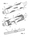
Figure 1 is a schematic view of a protective textile sleeve constructed in accordance with one aspect of the invention shown disposed about an elongate member; -
Figure 2 is a schematic view of a protective textile sleeve constructed in accordance with another aspect of the invention shown disposed about an elongate member; and -
Figure 3 is a partially broken away view of an extruded monofilament yarn used to construct the sleeve ofFigures 1 and 2 . - Referring in more detail to the drawings,
Figure 1 shows a tubular textile heat shield, also referred to astextile sleeve 10, constructed according to one embodiment of the invention for providing protection against heat to elongate members, such as wires or a wire harness 11, contained within thesleeve 10. Thetextile sleeve 10 has a plurality of yarns interlaced with one another, such as via a braiding process, by way of example and without limitation, to form atubular wall 12. Thewall 12 illustrated is seamless and circumferentially continuous having a reflectiveouter surface 14 and aninner surface 16 defining atubular cavity 18 extending axially along a centrallongitudinal axis 20 between oppositeopen ends sleeve 10. Thetubular cavity 18 is sized, as desired in manufacture, for receipt of the elongate members 11. The reflectiveouter surface 14 provides thewall 12 with a radiant heat resistance to protect the elongate members 11 against unwanted exposed to elevated temperatures. - The
wall 12 can be constructed having any suitable length and diameter and can be braided or otherwise constructed, i.e. woven, knitted, having a desired pattern for the intended application. Accordingly, thewall 12 can be constructed having various structural properties and configurations. Thewall 12 is constructed ofpolymeric monofilament yarns 26 interlaced with one another. As shown inFigure 3 , thepolymeric monofilament yarns 26 contain reflective aluminum particles orpowder granules 27 interspersed within the "as extruded"polymeric material 29 of themonofilaments 26, via a masterbatch compounding process. Thealuminum particles 27 provide the reflective outer surface 14 (by reflective outer surface it is intended to mean the outer exposed surface itself as well a depth immediately beneath the outer surface that contains aluminum particles encapsulated bypolymeric material 29 of the monofilament yarn 26) of thetubular wall 12 arid increase the radiant heat resistance of thepolymeric yarn 26, and the particles are odorless at an ignition temperature of about 600 degrees Celsius. Accordingly, thepolymeric yarn 26 is able to withstand increased temperatures from radiant heat sources, such as exhaust systems, for example, than if the reflective aluminum particles were not present. In addition, although thepolymeric yarn 26 containsaluminum particulate 27, the conductivity of thepolymeric monofilament yarn 26 remains the same or substantially the same as if thepolymeric material 29 were void or absent of thealuminum particulate 27, and thus, the conductivity of theyarn 26 is unaffected or substantially unaffected by the presence of the interspersedaluminum particles 27. - With the
polymeric yarn 26 containing the reflective aluminum particles, as extruded therein, the reflective heat resistant properties of thesleeve 10 are automatically provided upon interlacing theyarns 26 with one another. Accordingly, the need for secondary coating or layering operations to provide thesleeve 10 with heat resistance is negated, thereby offering economic efficiencies to the manufacture of thesleeve 10. Further, by allowing theyarns 26 to remain free from coating material or a reflective layer of material, theyarns 26 retain their full flexibility, both individually and relative to one another, given theyarns 26 are not bonded, glued or otherwise attached to one another by a coating material, and thus, thesleeve 10 is able to flex freely in use, and in addition, the weight of thesleeve 10 is minimized. - In
Figure 2 , asleeve 110 constructed in accordance with another aspect of the invention is shown, wherein the same reference numerals, offset by a factor of 100, are used to identify like features. - The
sleeve 110 is constructed with thesame yarn filaments 26 as discussed above, however, thesleeve 110 is constructed as a self-wrapping, "cigarette" type sleeve. As such, thesleeve 110 hasopposite edges longitudinal axis 120 betweenopposite ends sleeve 110. Upon forming awall 114 by interlacing thepolymeric yarn 26, thewall 114 is heat-set to take on its self-wrapping configuration, such that theopposite edges - In accordance with yet another aspect of the invention, a method of constructing a tubular
textile heat shield polymeric monofilament yarns 26 containingreflective aluminum particles 27 interspersed therein. Then, interlacing thepolymeric monofilament yarns 27 with one another and forming a textiletubular wall 114. - The method further includes heat-setting the aluminum particle containing
polymeric monofilament yarns 27 into a self-biasing tubular configuration. - The method further yet includes interspersing the
aluminum particles 27 having a density within thepolymeric monofilament yarns 26 that substantially leaves the conductivity of thepolymeric material 29 of thepolymeric yarns 26 unaffected along the full length of theyarns 26. - It should be recognized that
sleeves - It is to be understood that the above detailed description is with regard to some presently preferred embodiments, and that other embodiments readily discernible from the disclosure herein by those having ordinary skill in the art are incorporated herein and considered to be within the scope of any ultimately allowed claims.
Claims (4)
- A tubular textile heat shield (10; 110) for providing protection against heat to elongate members (11) contained therein, comprising:a tubular wall (12; 114) of interlaced yarn, said interlaced yarn including polymeric monofilament yarns (26) interlaced with one another, said polymeric monofilament yarns containing reflective aluminum particles (27) interspersed therein as extruded wherein the aluminum particles provide a reflective outer surface (14) and increase the radiant heat resistance of the yarn,characterised in that the conductivity of said polymeric monofilament yarns (26) is substantially unaffected by the interspersed aluminum particles (27).
- The tubular textile heat shield (110) of claim 1 wherein said polymeric monofilament yarns (26) are heat-set into a tubular configuration.
- A method of constructing a tubular textile heat shield (10; 110), comprising:providing extruded polymeric monofilament yarns (26) containing reflective aluminum particles (27) interspersed therein; andinterlacing the polymeric monofilament yarns with one another and forming a textile tubular wall (12; 114);
characterized by
providing the extruded polymeric monofilament yarns (26) having a density of aluminum particles (27) within the polymeric monofilament yarns that substantially leaves the conductivity of the polymeric material of the polymeric yarns unaffected along the full length of the yarns. - The method of claim 3 further including heat-setting the polymeric monofilament yarns (26) to bias the tubular wall (114) into a tubular configuration.
Applications Claiming Priority (2)
| Application Number | Priority Date | Filing Date | Title |
|---|---|---|---|
| US201161494927P | 2011-06-09 | 2011-06-09 | |
| PCT/US2012/041824 WO2012170981A2 (en) | 2011-06-09 | 2012-06-11 | Reflective textile sleeve and method of construction thereof |
Publications (2)
| Publication Number | Publication Date |
|---|---|
| EP2719039A2 EP2719039A2 (en) | 2014-04-16 |
| EP2719039B1 true EP2719039B1 (en) | 2015-05-06 |
Family
ID=46420534
Family Applications (1)
| Application Number | Title | Priority Date | Filing Date |
|---|---|---|---|
| EP20120731233 Active EP2719039B1 (en) | 2011-06-09 | 2012-06-11 | Reflective textile sleeve and method of construction thereof |
Country Status (6)
| Country | Link |
|---|---|
| US (1) | US20120315413A1 (en) |
| EP (1) | EP2719039B1 (en) |
| JP (1) | JP6258198B2 (en) |
| KR (1) | KR101972386B1 (en) |
| CN (1) | CN103733454B (en) |
| WO (1) | WO2012170981A2 (en) |
Families Citing this family (5)
| Publication number | Priority date | Publication date | Assignee | Title |
|---|---|---|---|---|
| US9277684B2 (en) * | 2013-03-13 | 2016-03-01 | Federal-Mogul Powertrain, Inc. | Self-wrapping EMI shielding textile sleeve and method of construction thereof |
| ES2576305B1 (en) * | 2014-12-05 | 2017-04-18 | Relats, S. A. | PACKAGING PROCEDURE FOR TRANSPORTATION AND DISTRIBUTION OF THERMAL AND ELECTROMAGNETIC PROTECTION COVERS |
| US10807341B2 (en) * | 2015-08-04 | 2020-10-20 | Federal-Mogul Powertrain Llc | Thermal sleeve with reflective positioning member, assembly therewith and method of construction thereof |
| US10208410B2 (en) * | 2015-11-13 | 2019-02-19 | Federal-Mogul Powertrain Llc | Braided textile sleeve with axially collapsible, anti-kinking feature and method of construction thereof |
| JP6607819B2 (en) * | 2016-04-01 | 2019-11-20 | 株式会社オオカワニット | Circular knitted tubular structure, manufacturing method thereof and manufacturing apparatus thereof |
Family Cites Families (12)
| Publication number | Priority date | Publication date | Assignee | Title |
|---|---|---|---|---|
| US2357851A (en) * | 1940-12-11 | 1944-09-12 | Scheyer Emanuel | Heat reflective material |
| US3038234A (en) * | 1953-07-09 | 1962-06-12 | Scheyer Emanuel | Heat reflective fabrics |
| KR100322737B1 (en) * | 1991-11-05 | 2002-06-20 | 존 앤터니 크럭스 | Fabric sleeves |
| US5413149A (en) * | 1991-11-05 | 1995-05-09 | The Bentley-Harris Manufacturing Company | Shaped fabric products and methods of making same |
| US5744206A (en) * | 1994-04-06 | 1998-04-28 | Vitrica, S.A. De C.V. | Braided sleeving with rib strands |
| US5843542A (en) * | 1997-11-10 | 1998-12-01 | Bentley-Harris Inc. | Woven fabric having improved flexibility and conformability |
| US6158576A (en) * | 1998-10-15 | 2000-12-12 | Albany International Corp. | Endless belt or fabric for use in process control loop |
| WO2005022564A2 (en) * | 2003-09-02 | 2005-03-10 | Integral Technologies, Inc. | Low cost electromagnetic energy absorbing, shrinkable tubing manufactured from conductive loaded resin-based materials |
| US20050136255A1 (en) * | 2003-12-15 | 2005-06-23 | Federal-Mogul World Wide, Inc. | High-strength abrasion-resistant monofilament yarn and sleeves formed therefrom |
| US9028937B2 (en) * | 2008-01-07 | 2015-05-12 | Federal-Mogul Powertrain, Inc. | Multilayer protective textile sleeve and method of construction |
| JP2009270218A (en) * | 2008-05-02 | 2009-11-19 | Diatex Co Ltd | Electromagnetic wave suppression flat yarn, electromagnetic wave suppression product using same, and method for producing the same |
| JP2010273488A (en) * | 2009-05-25 | 2010-12-02 | Ace Giken:Kk | Cover for protecting cable |
-
2012
- 2012-06-11 CN CN201280038171.2A patent/CN103733454B/en active Active
- 2012-06-11 KR KR1020147000541A patent/KR101972386B1/en active IP Right Grant
- 2012-06-11 JP JP2014514919A patent/JP6258198B2/en active Active
- 2012-06-11 WO PCT/US2012/041824 patent/WO2012170981A2/en active Application Filing
- 2012-06-11 EP EP20120731233 patent/EP2719039B1/en active Active
- 2012-06-11 US US13/493,661 patent/US20120315413A1/en not_active Abandoned
Also Published As
| Publication number | Publication date |
|---|---|
| WO2012170981A3 (en) | 2013-09-06 |
| KR20140041703A (en) | 2014-04-04 |
| JP6258198B2 (en) | 2018-01-10 |
| CN103733454A (en) | 2014-04-16 |
| KR101972386B1 (en) | 2019-04-25 |
| EP2719039A2 (en) | 2014-04-16 |
| US20120315413A1 (en) | 2012-12-13 |
| WO2012170981A2 (en) | 2012-12-13 |
| CN103733454B (en) | 2017-08-08 |
| JP2014524225A (en) | 2014-09-18 |
Similar Documents
| Publication | Publication Date | Title |
|---|---|---|
| EP2719039B1 (en) | Reflective textile sleeve and method of construction thereof | |
| EP2973904B1 (en) | End-fray resistant heat-shrinkable woven sleeve, assembly therewith and methods of construction thereof | |
| JP6837959B2 (en) | Protective sleeve with bonded wire filaments and how to build it | |
| EP2440695B1 (en) | Flexible, abrasion resistant textile sleeve and method of construction thereof | |
| EP3332054B1 (en) | Woven tubular thermal sleeve and method of construction thereof | |
| US8273429B2 (en) | Fabric for end fray resistance and protective sleeves formed therewith and methods of construction | |
| EP2331745B1 (en) | Self-wrapping textile sleeve with protective coating and method of construction thereof | |
| EP2951340B1 (en) | Non-kinking self-wrapping woven sleeve and method of construction thereof | |
| EP3368710B1 (en) | Self-wrapping, braided textile sleeve with self-sustaining expanded and contracted states and method of construction thereof | |
| US9277684B2 (en) | Self-wrapping EMI shielding textile sleeve and method of construction thereof | |
| EP3137663B1 (en) | Micro-perforated reflective textile sleeve and method of construction thereof | |
| EP2954109B1 (en) | Enhanced braided sleeve and method of construction thereof | |
| CN108633291B (en) | End wear resistant braided protective textile sleeve and method of construction thereof | |
| US6897375B2 (en) | Protective device for elongated objects | |
| EP3387171B1 (en) | Braided, reflective textile sleeve and method of construction thereof | |
| WO2019240917A1 (en) | Textile sleeve having elastomeric coating with indicator markings therein and method of construction thereof | |
| EP3146099B1 (en) | Flexible, abrasion resistant woven textile sleeve and method of contruction thereof | |
| CN113710839A (en) | Flexible abrasion resistant braided sleeve and method of construction thereof | |
| WO2023183639A1 (en) | Self-locating, dielectric, impact resistant textile sleeve and method of construction thereof | |
| DE20300436U1 (en) | Protective sheathing, for electrical wires and pipes in vehicles, comprises corrugated pipe with textile layer and external metal layer |
Legal Events
| Date | Code | Title | Description |
|---|---|---|---|
| PUAI | Public reference made under article 153(3) epc to a published international application that has entered the european phase |
Free format text: ORIGINAL CODE: 0009012 |
|
| 17P | Request for examination filed |
Effective date: 20131212 |
|
| AK | Designated contracting states |
Kind code of ref document: A2 Designated state(s): AL AT BE BG CH CY CZ DE DK EE ES FI FR GB GR HR HU IE IS IT LI LT LU LV MC MK MT NL NO PL PT RO RS SE SI SK SM TR |
|
| DAX | Request for extension of the european patent (deleted) | ||
| GRAP | Despatch of communication of intention to grant a patent |
Free format text: ORIGINAL CODE: EPIDOSNIGR1 |
|
| GRAJ | Information related to disapproval of communication of intention to grant by the applicant or resumption of examination proceedings by the epo deleted |
Free format text: ORIGINAL CODE: EPIDOSDIGR1 |
|
| GRAP | Despatch of communication of intention to grant a patent |
Free format text: ORIGINAL CODE: EPIDOSNIGR1 |
|
| INTG | Intention to grant announced |
Effective date: 20141117 |
|
| INTG | Intention to grant announced |
Effective date: 20141211 |
|
| GRAS | Grant fee paid |
Free format text: ORIGINAL CODE: EPIDOSNIGR3 |
|
| GRAA | (expected) grant |
Free format text: ORIGINAL CODE: 0009210 |
|
| AK | Designated contracting states |
Kind code of ref document: B1 Designated state(s): AL AT BE BG CH CY CZ DE DK EE ES FI FR GB GR HR HU IE IS IT LI LT LU LV MC MK MT NL NO PL PT RO RS SE SI SK SM TR |
|
| REG | Reference to a national code |
Ref country code: GB Ref legal event code: FG4D |
|
| REG | Reference to a national code |
Ref country code: CH Ref legal event code: EP |
|
| REG | Reference to a national code |
Ref country code: IE Ref legal event code: FG4D |
|
| REG | Reference to a national code |
Ref country code: AT Ref legal event code: REF Ref document number: 726272 Country of ref document: AT Kind code of ref document: T Effective date: 20150615 |
|
| REG | Reference to a national code |
Ref country code: DE Ref legal event code: R096 Ref document number: 602012007216 Country of ref document: DE Effective date: 20150618 |
|
| REG | Reference to a national code |
Ref country code: FR Ref legal event code: PLFP Year of fee payment: 4 |
|
| REG | Reference to a national code |
Ref country code: AT Ref legal event code: MK05 Ref document number: 726272 Country of ref document: AT Kind code of ref document: T Effective date: 20150506 |
|
| REG | Reference to a national code |
Ref country code: NL Ref legal event code: MP Effective date: 20150506 |
|
| REG | Reference to a national code |
Ref country code: LT Ref legal event code: MG4D |
|
| PG25 | Lapsed in a contracting state [announced via postgrant information from national office to epo] |
Ref country code: ES Free format text: LAPSE BECAUSE OF FAILURE TO SUBMIT A TRANSLATION OF THE DESCRIPTION OR TO PAY THE FEE WITHIN THE PRESCRIBED TIME-LIMIT Effective date: 20150506 Ref country code: LT Free format text: LAPSE BECAUSE OF FAILURE TO SUBMIT A TRANSLATION OF THE DESCRIPTION OR TO PAY THE FEE WITHIN THE PRESCRIBED TIME-LIMIT Effective date: 20150506 Ref country code: HR Free format text: LAPSE BECAUSE OF FAILURE TO SUBMIT A TRANSLATION OF THE DESCRIPTION OR TO PAY THE FEE WITHIN THE PRESCRIBED TIME-LIMIT Effective date: 20150506 Ref country code: PT Free format text: LAPSE BECAUSE OF FAILURE TO SUBMIT A TRANSLATION OF THE DESCRIPTION OR TO PAY THE FEE WITHIN THE PRESCRIBED TIME-LIMIT Effective date: 20150907 Ref country code: NO Free format text: LAPSE BECAUSE OF FAILURE TO SUBMIT A TRANSLATION OF THE DESCRIPTION OR TO PAY THE FEE WITHIN THE PRESCRIBED TIME-LIMIT Effective date: 20150806 Ref country code: FI Free format text: LAPSE BECAUSE OF FAILURE TO SUBMIT A TRANSLATION OF THE DESCRIPTION OR TO PAY THE FEE WITHIN THE PRESCRIBED TIME-LIMIT Effective date: 20150506 |
|
| PG25 | Lapsed in a contracting state [announced via postgrant information from national office to epo] |
Ref country code: GR Free format text: LAPSE BECAUSE OF FAILURE TO SUBMIT A TRANSLATION OF THE DESCRIPTION OR TO PAY THE FEE WITHIN THE PRESCRIBED TIME-LIMIT Effective date: 20150807 Ref country code: LV Free format text: LAPSE BECAUSE OF FAILURE TO SUBMIT A TRANSLATION OF THE DESCRIPTION OR TO PAY THE FEE WITHIN THE PRESCRIBED TIME-LIMIT Effective date: 20150506 Ref country code: IS Free format text: LAPSE BECAUSE OF FAILURE TO SUBMIT A TRANSLATION OF THE DESCRIPTION OR TO PAY THE FEE WITHIN THE PRESCRIBED TIME-LIMIT Effective date: 20150906 Ref country code: RS Free format text: LAPSE BECAUSE OF FAILURE TO SUBMIT A TRANSLATION OF THE DESCRIPTION OR TO PAY THE FEE WITHIN THE PRESCRIBED TIME-LIMIT Effective date: 20150506 Ref country code: AT Free format text: LAPSE BECAUSE OF FAILURE TO SUBMIT A TRANSLATION OF THE DESCRIPTION OR TO PAY THE FEE WITHIN THE PRESCRIBED TIME-LIMIT Effective date: 20150506 Ref country code: BG Free format text: LAPSE BECAUSE OF FAILURE TO SUBMIT A TRANSLATION OF THE DESCRIPTION OR TO PAY THE FEE WITHIN THE PRESCRIBED TIME-LIMIT Effective date: 20150806 |
|
| PG25 | Lapsed in a contracting state [announced via postgrant information from national office to epo] |
Ref country code: EE Free format text: LAPSE BECAUSE OF FAILURE TO SUBMIT A TRANSLATION OF THE DESCRIPTION OR TO PAY THE FEE WITHIN THE PRESCRIBED TIME-LIMIT Effective date: 20150506 Ref country code: DK Free format text: LAPSE BECAUSE OF FAILURE TO SUBMIT A TRANSLATION OF THE DESCRIPTION OR TO PAY THE FEE WITHIN THE PRESCRIBED TIME-LIMIT Effective date: 20150506 |
|
| REG | Reference to a national code |
Ref country code: CH Ref legal event code: PL |
|
| REG | Reference to a national code |
Ref country code: DE Ref legal event code: R097 Ref document number: 602012007216 Country of ref document: DE |
|
| PG25 | Lapsed in a contracting state [announced via postgrant information from national office to epo] |
Ref country code: CZ Free format text: LAPSE BECAUSE OF FAILURE TO SUBMIT A TRANSLATION OF THE DESCRIPTION OR TO PAY THE FEE WITHIN THE PRESCRIBED TIME-LIMIT Effective date: 20150506 Ref country code: MC Free format text: LAPSE BECAUSE OF FAILURE TO SUBMIT A TRANSLATION OF THE DESCRIPTION OR TO PAY THE FEE WITHIN THE PRESCRIBED TIME-LIMIT Effective date: 20150506 Ref country code: SK Free format text: LAPSE BECAUSE OF FAILURE TO SUBMIT A TRANSLATION OF THE DESCRIPTION OR TO PAY THE FEE WITHIN THE PRESCRIBED TIME-LIMIT Effective date: 20150506 Ref country code: RO Free format text: LAPSE BECAUSE OF NON-PAYMENT OF DUE FEES Effective date: 20150506 Ref country code: PL Free format text: LAPSE BECAUSE OF FAILURE TO SUBMIT A TRANSLATION OF THE DESCRIPTION OR TO PAY THE FEE WITHIN THE PRESCRIBED TIME-LIMIT Effective date: 20150506 |
|
| PLBE | No opposition filed within time limit |
Free format text: ORIGINAL CODE: 0009261 |
|
| STAA | Information on the status of an ep patent application or granted ep patent |
Free format text: STATUS: NO OPPOSITION FILED WITHIN TIME LIMIT |
|
| REG | Reference to a national code |
Ref country code: IE Ref legal event code: MM4A |
|
| 26N | No opposition filed |
Effective date: 20160209 |
|
| PG25 | Lapsed in a contracting state [announced via postgrant information from national office to epo] |
Ref country code: LI Free format text: LAPSE BECAUSE OF NON-PAYMENT OF DUE FEES Effective date: 20150630 Ref country code: IE Free format text: LAPSE BECAUSE OF NON-PAYMENT OF DUE FEES Effective date: 20150611 Ref country code: CH Free format text: LAPSE BECAUSE OF NON-PAYMENT OF DUE FEES Effective date: 20150630 |
|
| PG25 | Lapsed in a contracting state [announced via postgrant information from national office to epo] |
Ref country code: SI Free format text: LAPSE BECAUSE OF FAILURE TO SUBMIT A TRANSLATION OF THE DESCRIPTION OR TO PAY THE FEE WITHIN THE PRESCRIBED TIME-LIMIT Effective date: 20150506 |
|
| REG | Reference to a national code |
Ref country code: FR Ref legal event code: PLFP Year of fee payment: 5 |
|
| PG25 | Lapsed in a contracting state [announced via postgrant information from national office to epo] |
Ref country code: BE Free format text: LAPSE BECAUSE OF FAILURE TO SUBMIT A TRANSLATION OF THE DESCRIPTION OR TO PAY THE FEE WITHIN THE PRESCRIBED TIME-LIMIT Effective date: 20150506 |
|
| PG25 | Lapsed in a contracting state [announced via postgrant information from national office to epo] |
Ref country code: MT Free format text: LAPSE BECAUSE OF FAILURE TO SUBMIT A TRANSLATION OF THE DESCRIPTION OR TO PAY THE FEE WITHIN THE PRESCRIBED TIME-LIMIT Effective date: 20150506 |
|
| GBPC | Gb: european patent ceased through non-payment of renewal fee |
Effective date: 20160611 |
|
| REG | Reference to a national code |
Ref country code: FR Ref legal event code: PLFP Year of fee payment: 6 |
|
| PG25 | Lapsed in a contracting state [announced via postgrant information from national office to epo] |
Ref country code: HU Free format text: LAPSE BECAUSE OF FAILURE TO SUBMIT A TRANSLATION OF THE DESCRIPTION OR TO PAY THE FEE WITHIN THE PRESCRIBED TIME-LIMIT; INVALID AB INITIO Effective date: 20120611 Ref country code: SM Free format text: LAPSE BECAUSE OF FAILURE TO SUBMIT A TRANSLATION OF THE DESCRIPTION OR TO PAY THE FEE WITHIN THE PRESCRIBED TIME-LIMIT Effective date: 20150506 Ref country code: GB Free format text: LAPSE BECAUSE OF NON-PAYMENT OF DUE FEES Effective date: 20160611 |
|
| PG25 | Lapsed in a contracting state [announced via postgrant information from national office to epo] |
Ref country code: SE Free format text: LAPSE BECAUSE OF FAILURE TO SUBMIT A TRANSLATION OF THE DESCRIPTION OR TO PAY THE FEE WITHIN THE PRESCRIBED TIME-LIMIT Effective date: 20150506 Ref country code: CY Free format text: LAPSE BECAUSE OF FAILURE TO SUBMIT A TRANSLATION OF THE DESCRIPTION OR TO PAY THE FEE WITHIN THE PRESCRIBED TIME-LIMIT Effective date: 20150506 Ref country code: NL Free format text: LAPSE BECAUSE OF FAILURE TO SUBMIT A TRANSLATION OF THE DESCRIPTION OR TO PAY THE FEE WITHIN THE PRESCRIBED TIME-LIMIT Effective date: 20150506 |
|
| PG25 | Lapsed in a contracting state [announced via postgrant information from national office to epo] |
Ref country code: TR Free format text: LAPSE BECAUSE OF FAILURE TO SUBMIT A TRANSLATION OF THE DESCRIPTION OR TO PAY THE FEE WITHIN THE PRESCRIBED TIME-LIMIT Effective date: 20150506 |
|
| PG25 | Lapsed in a contracting state [announced via postgrant information from national office to epo] |
Ref country code: LU Free format text: LAPSE BECAUSE OF NON-PAYMENT OF DUE FEES Effective date: 20150611 |
|
| REG | Reference to a national code |
Ref country code: FR Ref legal event code: PLFP Year of fee payment: 7 |
|
| PG25 | Lapsed in a contracting state [announced via postgrant information from national office to epo] |
Ref country code: MK Free format text: LAPSE BECAUSE OF FAILURE TO SUBMIT A TRANSLATION OF THE DESCRIPTION OR TO PAY THE FEE WITHIN THE PRESCRIBED TIME-LIMIT Effective date: 20150506 |
|
| PG25 | Lapsed in a contracting state [announced via postgrant information from national office to epo] |
Ref country code: AL Free format text: LAPSE BECAUSE OF FAILURE TO SUBMIT A TRANSLATION OF THE DESCRIPTION OR TO PAY THE FEE WITHIN THE PRESCRIBED TIME-LIMIT Effective date: 20150506 |
|
| PGFP | Annual fee paid to national office [announced via postgrant information from national office to epo] |
Ref country code: IT Payment date: 20200611 Year of fee payment: 9 |
|
| PG25 | Lapsed in a contracting state [announced via postgrant information from national office to epo] |
Ref country code: IT Free format text: LAPSE BECAUSE OF NON-PAYMENT OF DUE FEES Effective date: 20210611 |
|
| P01 | Opt-out of the competence of the unified patent court (upc) registered |
Effective date: 20230528 |
|
| PGFP | Annual fee paid to national office [announced via postgrant information from national office to epo] |
Ref country code: DE Payment date: 20240521 Year of fee payment: 13 |
|
| PGFP | Annual fee paid to national office [announced via postgrant information from national office to epo] |
Ref country code: FR Payment date: 20240521 Year of fee payment: 13 |