EP0611277A1 - Air conditioning equipment - Google Patents
Air conditioning equipment Download PDFInfo
- Publication number
- EP0611277A1 EP0611277A1 EP94890030A EP94890030A EP0611277A1 EP 0611277 A1 EP0611277 A1 EP 0611277A1 EP 94890030 A EP94890030 A EP 94890030A EP 94890030 A EP94890030 A EP 94890030A EP 0611277 A1 EP0611277 A1 EP 0611277A1
- Authority
- EP
- European Patent Office
- Prior art keywords
- compartment
- vehicle
- air conditioning
- control unit
- air
- Prior art date
- Legal status (The legal status is an assumption and is not a legal conclusion. Google has not performed a legal analysis and makes no representation as to the accuracy of the status listed.)
- Granted
Links
Images
Classifications
-
- B—PERFORMING OPERATIONS; TRANSPORTING
- B61—RAILWAYS
- B61D—BODY DETAILS OR KINDS OF RAILWAY VEHICLES
- B61D27/00—Heating, cooling, ventilating, or air-conditioning
- B61D27/0018—Air-conditioning means, i.e. combining at least two of the following ways of treating or supplying air, namely heating, cooling or ventilating
-
- F—MECHANICAL ENGINEERING; LIGHTING; HEATING; WEAPONS; BLASTING
- F24—HEATING; RANGES; VENTILATING
- F24F—AIR-CONDITIONING; AIR-HUMIDIFICATION; VENTILATION; USE OF AIR CURRENTS FOR SCREENING
- F24F3/00—Air-conditioning systems in which conditioned primary air is supplied from one or more central stations to distributing units in the rooms or spaces where it may receive secondary treatment; Apparatus specially designed for such systems
- F24F3/044—Systems in which all treatment is given in the central station, i.e. all-air systems
- F24F3/048—Systems in which all treatment is given in the central station, i.e. all-air systems with temperature control at constant rate of air-flow
- F24F3/052—Multiple duct systems, e.g. systems in which hot and cold air are supplied by separate circuits from the central station to mixing chambers in the spaces to be conditioned
- F24F3/0525—Multiple duct systems, e.g. systems in which hot and cold air are supplied by separate circuits from the central station to mixing chambers in the spaces to be conditioned in which the air treated in the central station is reheated
Definitions
- the invention relates to an air conditioning system and a method for air conditioning the interior of a vehicle, in particular a rail vehicle.
- an air conditioning system with a central air conditioning unit is used, the output of which is connected via an air supply duct to at least one compartment or vehicle area of the vehicle, each compartment or each vehicle area further comprising a temperature sensor connected to a compartment control unit for measuring the internal temperature and at least one forced ventilation , floor heater controllable by the compartment control unit.
- a considerable disadvantage of known air conditioning systems is that there is an unsatisfactory temperature distribution within the compartment in cooling operation due to the introduction of the cooling air in the floor area.
- the arrangement of the supply air duct in the floor area has furthermore the disadvantage that it takes up a lot of space in the floor area and therefore undesirably restricts the passenger compartment.
- the comfort of a vehicle interior depends very much on the uniformity of the temperature stratification. In cooling mode, this is possible by introducing cooled supply air preheated to a certain temperature into the interior from above. Since such a system is also used to heat this interior, the temperature stratification of these systems in heating mode is generally such that warm air bubbles form in the ceiling area and a so-called cold air lake forms in the floor area. This inadequate temperature stratification in heating mode can be considerably improved by additionally operating floor radiators with constant output. If the compartment or vehicle door is opened frequently, however, this measure is inadequate, since new cold air flows into the floor area, particularly in the case of rail vehicles, and the additional heat required is supplied in the ceiling area, which means that the cold air lake, which repeatedly occurs in the floor area, heats up only very slowly becomes.
- the invention has for its object to provide an air conditioning system and a method for air conditioning the interior of a vehicle, in which the disadvantages of known devices are eliminated and a uniform temperature stratification is generated in both heating and cooling mode.
- this object is achieved on the basis of an air conditioning system of the type mentioned at the outset, in which the compartment control unit is connected to a secondary heating element, via which supply air flows into the compartment from above, this compartment control unit controlling the output of the floor heating element as a function of the temperature sensor during heating operation and the like Post-heating element is controlled so that the temperature of the supply air is kept approximately constant, and this compartment control unit controls the power output of the post-heating element as a function of the temperature sensor in cooling mode when the floor heating element is switched off.
- Each compartment control unit 3 of a passenger car is connected to a system control unit 9, which is also connected to the reheater 8 via the changeover switch 7, all of them Afterheater 8 of a car are each connected to the system control unit 9 via such a switch 7. Furthermore, this system control unit is connected to the air conditioner 10 of the passenger car and connected to a duct temperature sensor 11 and an outside temperature sensor 12. The fresh air outlet of the air conditioning unit 10 integrated in the ceiling area of the passenger coach is connected to a supply air duct 13 which extends in the longitudinal direction over the entire passenger coach. In the ceiling area of each compartment 2 there is a reheating element 8 within the supply air duct 13. Furthermore, the duct temperature sensor 11 is installed in the longitudinal direction approximately in the middle of the passenger car in this supply air duct 13.
- Fig. 2 the air conditioner runs in cooling mode.
- the changeover switch 7 and the switch 5 are in the position K, so that the reheater 8 is controlled via the compartment control unit 3, the floor heater 6 being switched off.
- the supply air supplied by the air conditioner 10 is preheated individually for this compartment, depending on the compartment temperature sensor 4 and under the control of the compartment control unit 3, before entering the compartment 2 by the reheating element 8.
- the temperature of the supply air supplied by the air conditioning unit 10 is therefore preferably somewhat below the lowest target temperature set in a compartment 2 of this passenger car. This cooled and optionally preheated supply air flows in the ceiling area essentially vertically downwards into compartment 2.
- the circulating air flowing in the floor area essentially horizontally from the floor heating elements 6 into the compartment is heated depending on the compartment temperature sensor 4 and under the control of the compartment control unit 3.
- the preferably horizontal inflow of the heated circulating air additionally accelerates the clearing out of the cold air lake which arises in the base area, in particular when the compartment door is opened.
- Criteria for the system according to the invention to run in cooling or heating mode or when this system is to be switched to the other operating mode can be defined in different ways.
- the operating mode is determined by the operating personnel. If this decision is made by the plant itself, it is generally dependent on several factors. An essential of these factors is the value for the outside temperature, which is measured by means of the outside temperature sensor 12 and communicated to the system control unit 9. At outside temperatures that are far above or below the compartment set temperature, the system control unit specifies the corresponding operating mode, after which the switch 5 or the changeover switch 7 is set to K (cool) or H (heat).
- the transition area in which the outside temperature is close to the target compartment temperature, other factors such as the different compartment temperatures measured in the passenger coach, the specified target values for these temperatures and the temperature in the supply air duct of this passenger coach are included in this decision.
- a suitable logic is installed in the system control unit, which determines which operation is the more economical, for example that with the lower energy consumption. This logic additionally, in particular in this critical temperature range, avoids unnecessary or frequent switching of the system from heating to cooling operation and vice versa.
- compartments do not necessarily have to be physically separate from one another, but can also be vehicle areas which are essentially air-conditioned independently of one another, so that different temperature requirements can also be taken into account within a single interior.
- this invention is not limited to passenger coaches, but can be applied to vehicles of all kinds, in particular also to tram / subway vehicles, buses or other vehicles with one or more compartments or vehicle areas.
Abstract
Description
Die Erfindung bezieht sich auf eine Klimaanlage und ein Verfahren zur Klimatisierung des Innenraumes eines Fahrzeuges, insbesondere eines Schienenfahrzeuges.The invention relates to an air conditioning system and a method for air conditioning the interior of a vehicle, in particular a rail vehicle.
Bei bekannten Verfahren zur Klimatisierung des Innenraumes eines Fahrzeuges, insbesondere eines Schienenfahrzeuges, wird zumindest einem Abteil oder Fahrzeugbereich, dessen Innentemperatur gemessen wird, Frisch- und/oder Warmluft zugeführt, wobei im Heizbetrieb in Abhängigkeit von einer vorgebbaren Solltemperatur erwärmte Umluft im Bodenbereich in das Abteil oder den Fahrzeugbereich eingebracht wird. Zur Realisierung dieses Verfahrens dient beispielsweise eine Klimaanlage mit einem zentralen Klimagerät, dessen Ausgang über einen Zuluftkanal mit zumindest einem Abteil oder Fahrzeugbereich des Fahrzeuges verbunden ist, wobei jedes Abteil oder jeder Fahrzeugbereich weiters einen mit einer Abteilsteuereinheit verbundenen Temperaturfühler zur Messung der Innentemperatur und zumindest einen zwangsbelüfteten, durch die Abteilsteuereinheit ansteuerbaren Bodenheizkörper aufweist.In known methods for air conditioning the interior of a vehicle, in particular a rail vehicle, fresh and / or warm air is supplied to at least one compartment or vehicle area whose interior temperature is measured, with heated circulating air in the floor area in the compartment depending on a predefinable target temperature or the vehicle area is brought. To implement this method, for example, an air conditioning system with a central air conditioning unit is used, the output of which is connected via an air supply duct to at least one compartment or vehicle area of the vehicle, each compartment or each vehicle area further comprising a temperature sensor connected to a compartment control unit for measuring the internal temperature and at least one forced ventilation , floor heater controllable by the compartment control unit.
Ein solches Verfahren bzw. eine Klimaanlage der oben genannten Art ist beispielsweise aus der DE-OS 2 205 448 bekannt. Darin ist eine Klimaanlage für ein Schienenfahrzeug beschrieben, bei welcher ein zentrales Klimagerät vorgesehen ist, welches über einen Zuluftkanal mit jedem Abteil des Fahrzeuges verbunden ist, wobei die vom Klimagerät gelieferte Zuluft über einen Zwischenerhitzer im Bodenbereich in das Abteil einströmt. In jedem Abteil ist weiters ein Temperaturfühler zur Messung der Innentemperatur und ein damit verbundener Regelkreis zur Steuerung des Zwischenerhitzers vorgesehen.Such a method or an air conditioning system of the type mentioned above is known for example from DE-OS 2 205 448. This describes an air conditioning system for a rail vehicle, in which a central air conditioning unit is provided, which is connected to each compartment of the vehicle via an air supply duct, the air supply supplied by the air conditioning unit flowing into the compartment via an intermediate heater in the floor area. In each compartment there is also a temperature sensor for measuring the inside temperature and a control loop connected to it for controlling the reheater.
Aus der EP-A2 0 169 833 ist ebenso eine Klimaanlage mit einer im Bodenbereich angeordneten Nachheizanlage bekannt geworden. Zusätzlich ist bei dieser Vorrichtung auch eine Umluftrückführung und eine Lufteinbringung im Fenster bzw. seitlichen Wandbereich vorgesehen.From EP-A2 0 169 833 an air conditioning system with a post-heating system arranged in the floor area has also become known. In addition, a recirculation of air and an introduction of air into the window or side wall area are also provided in this device.
Ein erheblicher Nachteil bekannter Klimaanlagen liegt jedoch darin, daß innerhalb des Abteils im Kühlbetrieb durch das Einbringen der Kühlluft im Bodenbereich eine unbefriedigende Temperaturverteilung herrscht. Die Anordnung des Zuluftkanals im Bodenbereich hat überdies den Nachteil, daß sie im Bodenbereich viel Platz beansprucht und daher den Fahrgastraum in unerwünschter Weise einschränkt.A considerable disadvantage of known air conditioning systems, however, is that there is an unsatisfactory temperature distribution within the compartment in cooling operation due to the introduction of the cooling air in the floor area. The arrangement of the supply air duct in the floor area has furthermore the disadvantage that it takes up a lot of space in the floor area and therefore undesirably restricts the passenger compartment.
Es ist weiters aus der GB-B 862 473 bekannt, im Heizbetrieb erwärmte Luft im Bodenbereich und im Kühlbetrieb Kühlluft von oben in einen Großraumwagen einzubringen. Es besteht jedoch keine Möglichkeit die Temperatur der eingebrachten Luft lokal zu beeinflussen.It is also known from GB-B 862 473 to introduce heated air in the floor area in the heating mode and cooling air from above into a open-top car in the cooling mode. However, there is no possibility of locally influencing the temperature of the air introduced.
Die Behaglichkeit eines Fahrzeuginnenraumes hängt sehr stark von der Gleichmäßigkeit der Temperaturschichtung ab. Im Kühlbetrieb ist dies durch Einbringen gekühlter, auf eine bestimmte Temperatur vorgewärmter Zuluft von oben in den Innenraum möglich. Da eine solche Anlage auch zum Heizen dieses Innenraumes benützt wird, ist die Temperaturschichtung dieser Anlagen im Heizbetrieb im allgemeinen so, daß sich im Deckenbereich Warmluftblasen und im Bodenbereich ein sogenannter Kaltluftsee ausbildet. Durch zusätzliches Betreiben von Bodenheizkörpern mit konstanter Leistung kann diese mangelhafte Temperaturschichtung im Heizbetrieb erheblich verbessert werden. Bei häufigem Öffnen der Abteil- oder Fahrzeugtür ist diese Maßnahme jedoch ungenügend, da hierbei, insbesondere bei Schienenfahrzeugen, von neuem Kaltluft in den Bodenbereich einströmt und die zusätzlich erforderliche Wärme im Deckenbereich nachgeliefert wird, wodurch der im Bodenbereich immer wieder entstehende Kaltluftsee nur sehr langsam erwärmt wird.The comfort of a vehicle interior depends very much on the uniformity of the temperature stratification. In cooling mode, this is possible by introducing cooled supply air preheated to a certain temperature into the interior from above. Since such a system is also used to heat this interior, the temperature stratification of these systems in heating mode is generally such that warm air bubbles form in the ceiling area and a so-called cold air lake forms in the floor area. This inadequate temperature stratification in heating mode can be considerably improved by additionally operating floor radiators with constant output. If the compartment or vehicle door is opened frequently, however, this measure is inadequate, since new cold air flows into the floor area, particularly in the case of rail vehicles, and the additional heat required is supplied in the ceiling area, which means that the cold air lake, which repeatedly occurs in the floor area, heats up only very slowly becomes.
Der Erfindung liegt die Aufgabe zugrunde, eine Klimaanlage und ein Verfahren zur Klimatisierung des Innenraumes eines Fahrzeuges anzugeben, bei welchem die Nachteile bekannter Vorrichtungen beseitigt werden und sowohl im Heiz- als auch im Kühlbetrieb eine gleichmäßige Temperaturschichtung erzeugt wird.The invention has for its object to provide an air conditioning system and a method for air conditioning the interior of a vehicle, in which the disadvantages of known devices are eliminated and a uniform temperature stratification is generated in both heating and cooling mode.
Diese Aufgabe wird durch ein Verfahren der eingangs genannten Art gelöst, bei welchem von oben in das Abteil oder den Fahrzeugbereich einströmende Zuluft im Kühlbetrieb in Abhängigkeit von der vorgegebenen Solltemperatur erwärmt und im Heizbetrieb auf annähernd konstante Temperatur gehalten wird.This object is achieved by a method of the type mentioned in the introduction, in which supply air flowing into the compartment or the vehicle area from above is heated in cooling mode as a function of the predetermined target temperature and is kept at an approximately constant temperature in heating mode.
Weiters wird diese Aufgabe anhand einer Klimaanlage der eingangs genannten Art gelöst, bei welcher die Abteilsteuereinheit mit einem Nachheizkörper verbunden ist, über welchen Zuluft von oben in das Abteil einströmt, wobei diese Abteilsteuereinheit im Heizbetrieb die Leistungsabgabe des Bodenheizkörpers in Abhängigkeit von dem Temperaturfühler steuert und der Nachheizkörper so gesteuert wird, daß die Temperatur der Zuluft annähernd konstant gehalten wird, und wobei diese Abteilsteuereinheit im Kühlbetrieb bei abgeschaltetem Bodenheizkörper die Leistungsabgabe des Nachheizkörpers in Abhängigkeit von dem Temperaturfühler steuert.Furthermore, this object is achieved on the basis of an air conditioning system of the type mentioned at the outset, in which the compartment control unit is connected to a secondary heating element, via which supply air flows into the compartment from above, this compartment control unit controlling the output of the floor heating element as a function of the temperature sensor during heating operation and the like Post-heating element is controlled so that the temperature of the supply air is kept approximately constant, and this compartment control unit controls the power output of the post-heating element as a function of the temperature sensor in cooling mode when the floor heating element is switched off.
Weitere Ausgestaltungsmerkmale der erfindungsgemäßen Klimaanlage werden in den abhängigen Unteransprüchen 3 bis 7 beschrieben.Further design features of the air conditioning system according to the invention are described in the
Die Erfindung wird unter Bezugnahme auf die Figuren 1 bis 3 anhand eines Ausführungsbeispiels einer erfindungsgemäßen Klimaanlage an einem Reisezugwagen näher erläutert, wobei die beiliegenden Figuren folgendes zeigen:
Figur 1 einen schematischen Längsschnitt durch einen Reisezugwagen, der mit einer erfindungsgemäßen Klimaanlage versehen ist,Figur 2 einen schematischen Querschnitt durch den Reisezugwagen von Fig. 1, wobei die Klimaanlage im Kühlbetrieb betrieben wird,Figur 3 einen schematischen Querschnitt durch den Reisezugwagen von Fig. 1, wobei die Klimaanlage im Heizbetrieb betrieben wird.
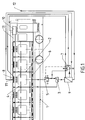
- FIG. 1 shows a schematic longitudinal section through a passenger coach which is provided with an air conditioning system according to the invention,
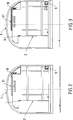
- FIG. 2 shows a schematic cross section through the passenger coach of FIG. 1, the air conditioning system being operated in cooling mode,
- 3 shows a schematic cross section through the passenger coach of FIG. 1, the air conditioning system being operated in heating mode.
Es wird zunächst auf Fig. 1 bezug genommen, in welcher ein Reisezugwagen 1 mit mehreren, im wesentlichen identischen Abteilen 2 gezeigt ist. Aus Gründen der Übersichtlichkeit ist die Steuerung der Klimaanlage nur an einem solchen Abteil 2 dargestellt. Das wesentliche Element der Steuerung ist eine Abteilsteuereinheit 3, an welcher ein Abteiltemperaturfühler 4 angeschlossen ist und welche über einen Schalter 5 mit einem Bodenheizkörper 6 und über einen Umschalter 7 mit einem Nachheizkörper 8 verbunden ist. Die beiden Schalter 5 und 7 sind mit einem Ausgang der Abteilsteuereinheit 3 verbunden und so miteinander gekoppelt, daß bei Betätigen des Schalters 5 auch der Umschalter betätigt wird und umgekehrt. Im Heizbetrieb sind die beiden Schalter in der in Fig. 1 dargestellten Stellung H und im Kühlbetrieb in der Stellung K. Jede Abteilsteuereinheit 3 eines Reisezugwagens ist mit einer Anlagensteuereinheit 9 verbunden, welche ebenso über den Umschalter 7 mit dem Nachheizkörper 8 verbunden ist, wobei alle Nachheizkörper 8 eines Wagens über je einen solchen Umschalter 7 mit der Anlagensteuereinheit 9 verbunden sind. Weiters ist diese Anlagensteuereinheit mit dem Klimagerät 10 des Reisezugwagens verbunden und an einen Kanaltemperaturfühler 11 und einen Außentemperaturfühler 12 angeschlossen. Der Frischluftausgang des im Deckenbereich des Reisezugwagens integrierten Klimagerätes 10 ist mit einem Zuluftkanal 13 verbunden, der sich in Längsrichtung über den gesamten Reisezugwagen erstreckt. Im Deckenbereich jedes Abteils 2 befindet sich innerhalb des Zuluftkanals 13 je ein Nachheizkörper 8. Weiters ist in Längsrichtung etwa in der Mitte des Reisezugwagens in diesem Zuluftkanal 13 der Kanaltemperaturfühler 11 eingebaut.Reference is first made to FIG. 1, in which a
Die Funktionsweise einer solchen Klimaanlage wird im folgenden unter Bezugnahme auf die Fig. 2 und 3 beschrieben.The operation of such an air conditioner is described below with reference to FIGS. 2 and 3.
In Fig. 2 läuft die Klimaanlage im Kühlbetrieb. Hierbei befinden sich der Umschalter 7 und der Schalter 5 in der Stellung K, sodaß der Nachheizkörper 8 über die Abteilsteuereinheit 3 gesteuert wird, wobei der Bodenheizkörper 6 abgeschaltet ist. Dadurch wird die vom Klimagerät 10 gelieferte Zuluft abhängig von dem Abteiltemperaturfühler 4 und unter Steuerung durch die Abteilsteuereinheit 3 vor dem Eintreten in das Abteil 2 von dem Nachheizkörper 8 individuell für dieses Abteil vorgewärmt. Die Temperatur der von dem Klimagerät 10 angelieferten Zuluft liegt deshalb vorzugsweise etwas unterhalb der niedrigsten, in einem Abteil 2 dieses Reisezugwagens eingestellten Solltemperatur. Diese gekühlte und gegebenenfalls vorgewärmte Zuluft strömt im Deckenbereich im wesentlichen senkrecht nach unten in das Abteil 2 ein.In Fig. 2 the air conditioner runs in cooling mode. Here, the
In Fig. 3 ist die Klimaanlage im Heizbetrieb dargestellt. Dabei befinden sich der Umschalter 7 und der Schalter 5 in der Stellung H, sodaß der Bodenheizkörper 6 über die Abteilsteuereinheit 3 gesteuert wird und der Nachheizkörper 8 nun mit der Anlagensteuereinheit 9 verbunden ist. Die Anlagensteuereinheit sorgt im Heizbetrieb dafür, daß die Zuluft durch die Nachheizkörper auf eine annähernd konstante, im Bereich der Solltemperatur liegende Temperatur vorgewärmt wird. Für praktische Zwecke liegt diese Temperatur geringfügig über der niedrigsten, in einem Abteil 2 des Reisezugwagens vorgegebenen Solltemperatur und wird von dem Kanaltemperaturfühler 11 überwacht. Die individuelle Regelung der Abteiltemperatur wird im Heizbetrieb der erfindungsgemäßen Klimaanlage über die Bodenheizkörper 6 verwirklicht. Die im Bodenbereich im wesentlichen horizontal aus den Bodenheizkörpern 6 in das Abteil einströmende Umluft wird dabei in Abhängigkeit von dem Abteiltemperaturfühler 4 und unter Steuerung durch die Abteilsteuereinheit 3 erwärmt. Das vorzugsweise horizontale Einströmen der gewärmten Umluft beschleunigt zusätzlich das Ausräumen des im Bodenbereich, insbesondere bei Öffnen der Abteiltür entstehenden Kaltluftsees.In Fig. 3 the air conditioning system is shown in heating mode. The
Kriterien dafür, daß die erfindungsgemäße Anlage im Kühl- oder Heizbetrieb laufen soll bzw. wann diese Anlage auf den jeweils anderen Betriebsmodus umgeschaltet werden soll, können auf unterschiedliche Weise definiert werden. Im einfachsten Fall wird der Betriebsmodus von dem Bedienungspersonal festgelegt. Falls diese Entscheidung von der Anlage selbst getroffen wird, ist sie ist allgemeinen von mehreren Faktoren abhängig. Ein wesentlicher dieser Faktoren ist der Wert für die Außentemperatur, welcher mittels des Außentemperaturfühlers 12 gemessen und der Anlagensteuereinheit 9 mitgeteilt wird. Bei Außentemperaturen, die weit über oder unter der Abteilsolltemperatur liegen, gibt die Anlagensteuereinheit die entsprechende Betriebsform vor, wonach der Schalter 5 bzw. der Umschalter 7 auf K (kühlen) oder H (heizen) gestellt wird. Im Übergangsbereich, in welchem die Außentemperatur nahe an der Abteilsolltemperatur liegt, werden weitere Faktoren, wie die in dem Reisezugwagen gemessenen unterschiedlichen Abteiltemperaturen, die vorgegebenen Sollwerte für diese Temperaturen und die Temperatur im Zuluftkanal dieses Reisezugwagens in diese Entscheidung mit einbezogen. Ebenso gibt es einen Temperaturbereich, bei welchem die Klimaanlage sowohl im Heizbetrieb als auch im Kühlbetrieb betrieben werden kann, um die erforderlichen Abteiltemperaturen eines Reisezugwagens herzustellen. Zu diesem Zweck ist in der Anlagensteuereinheit eine geeignete Logik eingebaut, die feststellt, welcher Betrieb der günstigere ist, beispielsweise jener mit dem geringeren Energieverbrauch. Durch diese Logik wird, insbesondere in diesem kritischen Temperaturbereich zusätzlich ein unnötiges oder häufiges Umschalten der Anlage von Heiz- auf Kühlbetrieb und umgekehrt vermieden.Criteria for the system according to the invention to run in cooling or heating mode or when this system is to be switched to the other operating mode can be defined in different ways. In the simplest case, the operating mode is determined by the operating personnel. If this decision is made by the plant itself, it is generally dependent on several factors. An essential of these factors is the value for the outside temperature, which is measured by means of the
Wenn in dem obigen Ausführungsbeispiel von Abteilen die Rede ist, so müssen diese nicht notwendigerweise physisch voneinander getrennt sein, sondern können auch Fahrzeugbereiche sein, welche im wesenlichen unabhängig voneinander klimatisiert werden, sodaß auf unterschiedliche Temperaturanforderungen auch innerhalb eines einzelnen Innenraumes Rücksicht genommen werden kann.If the above exemplary embodiment refers to compartments, these do not necessarily have to be physically separate from one another, but can also be vehicle areas which are essentially air-conditioned independently of one another, so that different temperature requirements can also be taken into account within a single interior.
Bei einer hier nicht gezeigten Ausführungsform der Erfindung, bei welcher der Reisezugwagen ein Großraumabteil besitzt, können die Nachheizkörper in vorteilhafter Weise auch in dem Klimagerät integriert sein.In an embodiment of the invention, not shown here, in which the passenger coach has a large compartment, the post-heating elements can advantageously also be integrated in the air conditioning unit.
Abschließend ist noch anzumerken, daß diese Erfindung nicht nur auf Reisezugwagen beschränkt ist, sondern auf Fahrzeuge jeder Art angewendet werden kann, insbesondere auch auf Straßenbahn-/U-Bahnfahrzeuge, Busse oder andere Fahrzeuge mit einem oder mehreren Abteilen bzw. Fahrzeugbereichen.Finally, it should be noted that this invention is not limited to passenger coaches, but can be applied to vehicles of all kinds, in particular also to tram / subway vehicles, buses or other vehicles with one or more compartments or vehicle areas.
Claims (7)
Applications Claiming Priority (2)
| Application Number | Priority Date | Filing Date | Title |
|---|---|---|---|
| AT0026093A AT402722B (en) | 1993-02-12 | 1993-02-12 | METHOD FOR THE AIR CONDITIONING AND AIR CONDITIONING OF A VEHICLE, IN PARTICULAR A RAIL VEHICLE |
| AT260/93 | 1993-02-12 |
Publications (2)
| Publication Number | Publication Date |
|---|---|
| EP0611277A1 true EP0611277A1 (en) | 1994-08-17 |
| EP0611277B1 EP0611277B1 (en) | 1996-05-22 |
Family
ID=3485818
Family Applications (1)
| Application Number | Title | Priority Date | Filing Date |
|---|---|---|---|
| EP94890030A Expired - Lifetime EP0611277B1 (en) | 1993-02-12 | 1994-02-04 | Air conditioning equipment |
Country Status (5)
| Country | Link |
|---|---|
| EP (1) | EP0611277B1 (en) |
| AT (2) | AT402722B (en) |
| DE (1) | DE59400288D1 (en) |
| ES (1) | ES2087804T3 (en) |
| GR (1) | GR3020644T3 (en) |
Cited By (5)
| Publication number | Priority date | Publication date | Assignee | Title |
|---|---|---|---|---|
| DE29601806U1 (en) * | 1996-02-03 | 1996-04-11 | Hagenuk Fahrzeugklima Gmbh | Device for distributing the cooling and heating air for multi-compartment cars |
| CN101428624B (en) * | 2007-07-13 | 2013-03-13 | 阿尔斯通运输股份有限公司 | Air conditioning system for a compartment of a rail vehicle, corresponding rail vehicle and air conditioning method thereof |
| DE102015216404A1 (en) * | 2015-08-27 | 2017-03-02 | Siemens Aktiengesellschaft | Air conditioning arrangement for a rail vehicle |
| CN108248624A (en) * | 2017-12-28 | 2018-07-06 | 河南辉煌信通软件有限公司 | The temperature detection and regulating system of motor train compartment |
| EP3795446A1 (en) * | 2019-09-19 | 2021-03-24 | ALSTOM Transport Technologies | Passenger transport vehicle comprising at least one heating fan, vehicle and associated method for adjusting the air temperature |
Families Citing this family (1)
| Publication number | Priority date | Publication date | Assignee | Title |
|---|---|---|---|---|
| DE10304272B4 (en) * | 2003-02-03 | 2006-10-12 | Siemens Ag | Method for conditioning the interior of a vehicle |
Citations (2)
| Publication number | Priority date | Publication date | Assignee | Title |
|---|---|---|---|---|
| DE2524400A1 (en) * | 1974-10-23 | 1976-04-29 | Friedmann Kg Alex | Railway vehicle air-conditioning system - has overall temp. control by internal and external sensors and individual adjustment in each compartment(OE-15.1.76) |
| DE3048226A1 (en) * | 1980-12-20 | 1982-07-15 | Brown, Boveri & Cie Ag, 6800 Mannheim | FACILITIES FOR AIR CONDITIONING |
Family Cites Families (3)
| Publication number | Priority date | Publication date | Assignee | Title |
|---|---|---|---|---|
| GB862473A (en) * | 1958-06-20 | 1961-03-08 | Stone J & Co Ltd | Improvements relating to temperature control in vehicles by automatic hot and cold air distribution |
| FR2131025A5 (en) * | 1971-03-30 | 1972-11-10 | Jouvenel & Cordier | |
| AT382566B (en) * | 1984-07-27 | 1987-03-10 | Friedmann Kg Alex | RAILWAY TROLLEY WITH A HEATING OR AIR CONDITIONER |
-
1993
- 1993-02-12 AT AT0026093A patent/AT402722B/en not_active IP Right Cessation
-
1994
- 1994-02-04 DE DE59400288T patent/DE59400288D1/en not_active Expired - Fee Related
- 1994-02-04 EP EP94890030A patent/EP0611277B1/en not_active Expired - Lifetime
- 1994-02-04 ES ES94890030T patent/ES2087804T3/en not_active Expired - Lifetime
- 1994-02-04 AT AT94890030T patent/ATE138332T1/en not_active IP Right Cessation
-
1996
- 1996-07-26 GR GR960402000T patent/GR3020644T3/en unknown
Patent Citations (2)
| Publication number | Priority date | Publication date | Assignee | Title |
|---|---|---|---|---|
| DE2524400A1 (en) * | 1974-10-23 | 1976-04-29 | Friedmann Kg Alex | Railway vehicle air-conditioning system - has overall temp. control by internal and external sensors and individual adjustment in each compartment(OE-15.1.76) |
| DE3048226A1 (en) * | 1980-12-20 | 1982-07-15 | Brown, Boveri & Cie Ag, 6800 Mannheim | FACILITIES FOR AIR CONDITIONING |
Cited By (7)
| Publication number | Priority date | Publication date | Assignee | Title |
|---|---|---|---|---|
| DE29601806U1 (en) * | 1996-02-03 | 1996-04-11 | Hagenuk Fahrzeugklima Gmbh | Device for distributing the cooling and heating air for multi-compartment cars |
| CN101428624B (en) * | 2007-07-13 | 2013-03-13 | 阿尔斯通运输股份有限公司 | Air conditioning system for a compartment of a rail vehicle, corresponding rail vehicle and air conditioning method thereof |
| DE102015216404A1 (en) * | 2015-08-27 | 2017-03-02 | Siemens Aktiengesellschaft | Air conditioning arrangement for a rail vehicle |
| CN108248624A (en) * | 2017-12-28 | 2018-07-06 | 河南辉煌信通软件有限公司 | The temperature detection and regulating system of motor train compartment |
| CN108248624B (en) * | 2017-12-28 | 2019-07-19 | 河南辉煌信通软件有限公司 | The temperature detection and regulating system of motor train compartment |
| EP3795446A1 (en) * | 2019-09-19 | 2021-03-24 | ALSTOM Transport Technologies | Passenger transport vehicle comprising at least one heating fan, vehicle and associated method for adjusting the air temperature |
| FR3101021A1 (en) * | 2019-09-19 | 2021-03-26 | Alstom Transport Technologies | Passenger transport car comprising at least one heating fan, vehicle and associated air temperature adjustment method |
Also Published As
| Publication number | Publication date |
|---|---|
| ATA26093A (en) | 1996-12-15 |
| DE59400288D1 (en) | 1996-06-27 |
| EP0611277B1 (en) | 1996-05-22 |
| AT402722B (en) | 1997-08-25 |
| GR3020644T3 (en) | 1996-10-31 |
| ATE138332T1 (en) | 1996-06-15 |
| ES2087804T3 (en) | 1996-07-16 |
Similar Documents
| Publication | Publication Date | Title |
|---|---|---|
| DE10361709B4 (en) | Device and method for controlling the temperature of parts of the interior of an aircraft | |
| EP1607254B1 (en) | Device for supplying air to the interior of a vehicle | |
| DE3016679A1 (en) | VENTILATION, HEATING AND / OR AIR CONDITIONING FOR MOTOR VEHICLES | |
| EP0611277B1 (en) | Air conditioning equipment | |
| EP0212306A2 (en) | Heating and ventilating device for motor vehicles | |
| EP0131888B1 (en) | Temperature-dependent control for a bus's interior heating | |
| DE202013105090U1 (en) | Multifunction HVAC air system for one vehicle | |
| DE4214703A1 (en) | METHOD AND AIR CONDITIONER FOR CONTROLLING THE CLIMATE IN AN INTERIOR OF A VEHICLE CONSTRUCTING A FIRST AND A SECOND HALF ROOM | |
| DE4412486C2 (en) | Method for controlling and regulating an air conditioning system or automatic system for motor vehicles | |
| EP1187733B1 (en) | Device for controlling the interior temperature of a motor vehicle | |
| AT244382B (en) | Device for regulating the temperature in passenger compartments of vehicles, in particular rail vehicles | |
| DE102009060902B4 (en) | Air conditioning an interior of a vehicle with a ventilation device | |
| DE2928134A1 (en) | Temp. control for passenger compartment of bus - regulates air flow by altering ventilation fan speed and fresh-air inlet flap | |
| DE102008005758B4 (en) | Method for networked control of an air conditioning system influencing an interior climate of a motor vehicle | |
| AT403790B (en) | METHOD FOR CONTROLLING AN AIR CONDITIONING OF A VEHICLE, IN PARTICULAR AN ELECTRICALLY OPERATED RAIL VEHICLE | |
| EP0149450B1 (en) | Air conditioning device for railroad vehicles | |
| DE1580967B2 (en) | PROCESS FOR AIR CONDITIONING OF PASSENGER COMPARTMENTS OF RAIL VEHICLES AND ARRANGEMENT FOR THE IMPLEMENTATION | |
| CH648922A5 (en) | Device for air-conditioning a number of rooms | |
| DE2038912C3 (en) | Air conditioning for vehicles, in particular rail vehicles | |
| WO2018077591A1 (en) | Apparatus for the individual climate control of separate spaces | |
| DE2613608A1 (en) | Single-channel air conditioning for rail vehicles - uses air temperature controlled switch-over flap to direct air into upward extending outlet shaft (OE150576) | |
| DE2310411C3 (en) | Device for regulating the temperature in passenger compartments of vehicles, in particular rail vehicles | |
| DE2443258A1 (en) | Single-channel air conditioning for rail vehicles - contains after heaters charged by partial air flow from water boiler | |
| DE2443258C2 (en) | Single-channel air conditioning for rail vehicles | |
| EP0757943A2 (en) | Method of regulating the temperature inside a motor vehicle |
Legal Events
| Date | Code | Title | Description |
|---|---|---|---|
| PUAI | Public reference made under article 153(3) epc to a published international application that has entered the european phase |
Free format text: ORIGINAL CODE: 0009012 |
|
| AK | Designated contracting states |
Kind code of ref document: A1 Designated state(s): AT DE ES GR IT PT |
|
| 17P | Request for examination filed |
Effective date: 19940704 |
|
| 17Q | First examination report despatched |
Effective date: 19950619 |
|
| GRAA | (expected) grant |
Free format text: ORIGINAL CODE: 0009210 |
|
| AK | Designated contracting states |
Kind code of ref document: B1 Designated state(s): AT DE ES GR IT PT |
|
| REF | Corresponds to: |
Ref document number: 138332 Country of ref document: AT Date of ref document: 19960615 Kind code of ref document: T |
|
| ITF | It: translation for a ep patent filed |
Owner name: STUDIO GLP S.R.L. |
|
| REG | Reference to a national code |
Ref country code: ES Ref legal event code: BA2A Ref document number: 2087804 Country of ref document: ES Kind code of ref document: T3 |
|
| REF | Corresponds to: |
Ref document number: 59400288 Country of ref document: DE Date of ref document: 19960627 |
|
| REG | Reference to a national code |
Ref country code: ES Ref legal event code: FG2A Ref document number: 2087804 Country of ref document: ES Kind code of ref document: T3 |
|
| REG | Reference to a national code |
Ref country code: GR Ref legal event code: FG4A Free format text: 3020644 |
|
| SC4A | Pt: translation is available |
Free format text: 960822 AVAILABILITY OF NATIONAL TRANSLATION |
|
| PLBE | No opposition filed within time limit |
Free format text: ORIGINAL CODE: 0009261 |
|
| STAA | Information on the status of an ep patent application or granted ep patent |
Free format text: STATUS: NO OPPOSITION FILED WITHIN TIME LIMIT |
|
| 26N | No opposition filed | ||
| PGFP | Annual fee paid to national office [announced via postgrant information from national office to epo] |
Ref country code: GR Payment date: 19990129 Year of fee payment: 6 |
|
| PGFP | Annual fee paid to national office [announced via postgrant information from national office to epo] |
Ref country code: PT Payment date: 19990203 Year of fee payment: 6 |
|
| PGFP | Annual fee paid to national office [announced via postgrant information from national office to epo] |
Ref country code: ES Payment date: 19990211 Year of fee payment: 6 |
|
| PGFP | Annual fee paid to national office [announced via postgrant information from national office to epo] |
Ref country code: AT Payment date: 19990219 Year of fee payment: 6 |
|
| PGFP | Annual fee paid to national office [announced via postgrant information from national office to epo] |
Ref country code: DE Payment date: 19990303 Year of fee payment: 6 |
|
| PG25 | Lapsed in a contracting state [announced via postgrant information from national office to epo] |
Ref country code: AT Free format text: LAPSE BECAUSE OF NON-PAYMENT OF DUE FEES Effective date: 20000204 |
|
| PG25 | Lapsed in a contracting state [announced via postgrant information from national office to epo] |
Ref country code: ES Free format text: LAPSE BECAUSE OF NON-PAYMENT OF DUE FEES Effective date: 20000205 |
|
| PG25 | Lapsed in a contracting state [announced via postgrant information from national office to epo] |
Ref country code: GR Free format text: LAPSE BECAUSE OF NON-PAYMENT OF DUE FEES Effective date: 20000229 |
|
| PG25 | Lapsed in a contracting state [announced via postgrant information from national office to epo] |
Ref country code: PT Free format text: LAPSE BECAUSE OF NON-PAYMENT OF DUE FEES Effective date: 20000831 |
|
| PG25 | Lapsed in a contracting state [announced via postgrant information from national office to epo] |
Ref country code: DE Free format text: LAPSE BECAUSE OF NON-PAYMENT OF DUE FEES Effective date: 20001201 |
|
| REG | Reference to a national code |
Ref country code: PT Ref legal event code: MM4A Free format text: LAPSE DUE TO NON-PAYMENT OF FEES Effective date: 20000831 |
|
| REG | Reference to a national code |
Ref country code: ES Ref legal event code: FD2A Effective date: 20011010 |
|
| PG25 | Lapsed in a contracting state [announced via postgrant information from national office to epo] |
Ref country code: IT Free format text: LAPSE BECAUSE OF NON-PAYMENT OF DUE FEES Effective date: 20050204 |