EP0611187B1 - Appareil de découpage rotatif - Google Patents
Appareil de découpage rotatif Download PDFInfo
- Publication number
- EP0611187B1 EP0611187B1 EP94400224A EP94400224A EP0611187B1 EP 0611187 B1 EP0611187 B1 EP 0611187B1 EP 94400224 A EP94400224 A EP 94400224A EP 94400224 A EP94400224 A EP 94400224A EP 0611187 B1 EP0611187 B1 EP 0611187B1
- Authority
- EP
- European Patent Office
- Prior art keywords
- bearing block
- elastic means
- cutting
- vertical
- stop
- Prior art date
- Legal status (The legal status is an assumption and is not a legal conclusion. Google has not performed a legal analysis and makes no representation as to the accuracy of the status listed.)
- Expired - Lifetime
Links
Images
Classifications
-
- B—PERFORMING OPERATIONS; TRANSPORTING
- B26—HAND CUTTING TOOLS; CUTTING; SEVERING
- B26D—CUTTING; DETAILS COMMON TO MACHINES FOR PERFORATING, PUNCHING, CUTTING-OUT, STAMPING-OUT OR SEVERING
- B26D7/00—Details of apparatus for cutting, cutting-out, stamping-out, punching, perforating, or severing by means other than cutting
- B26D7/26—Means for mounting or adjusting the cutting member; Means for adjusting the stroke of the cutting member
- B26D7/2628—Means for adjusting the position of the cutting member
- B26D7/265—Journals, bearings or supports for positioning rollers or cylinders relatively to each other
-
- B—PERFORMING OPERATIONS; TRANSPORTING
- B21—MECHANICAL METAL-WORKING WITHOUT ESSENTIALLY REMOVING MATERIAL; PUNCHING METAL
- B21B—ROLLING OF METAL
- B21B29/00—Counter-pressure devices acting on rolls to inhibit deflection of same under load, e.g. backing rolls ; Roll bending devices, e.g. hydraulic actuators acting on roll shaft ends
-
- B—PERFORMING OPERATIONS; TRANSPORTING
- B26—HAND CUTTING TOOLS; CUTTING; SEVERING
- B26D—CUTTING; DETAILS COMMON TO MACHINES FOR PERFORATING, PUNCHING, CUTTING-OUT, STAMPING-OUT OR SEVERING
- B26D7/00—Details of apparatus for cutting, cutting-out, stamping-out, punching, perforating, or severing by means other than cutting
- B26D7/26—Means for mounting or adjusting the cutting member; Means for adjusting the stroke of the cutting member
- B26D7/2628—Means for adjusting the position of the cutting member
-
- B—PERFORMING OPERATIONS; TRANSPORTING
- B26—HAND CUTTING TOOLS; CUTTING; SEVERING
- B26F—PERFORATING; PUNCHING; CUTTING-OUT; STAMPING-OUT; SEVERING BY MEANS OTHER THAN CUTTING
- B26F1/00—Perforating; Punching; Cutting-out; Stamping-out; Apparatus therefor
- B26F1/38—Cutting-out; Stamping-out
- B26F1/384—Cutting-out; Stamping-out using rotating drums
-
- B—PERFORMING OPERATIONS; TRANSPORTING
- B21—MECHANICAL METAL-WORKING WITHOUT ESSENTIALLY REMOVING MATERIAL; PUNCHING METAL
- B21B—ROLLING OF METAL
- B21B31/00—Rolling stand structures; Mounting, adjusting, or interchanging rolls, roll mountings, or stand frames
- B21B31/16—Adjusting or positioning rolls
- B21B31/20—Adjusting or positioning rolls by moving rolls perpendicularly to roll axis
- B21B31/22—Adjusting or positioning rolls by moving rolls perpendicularly to roll axis mechanically, e.g. by thrust blocks, inserts for removal
- B21B31/24—Adjusting or positioning rolls by moving rolls perpendicularly to roll axis mechanically, e.g. by thrust blocks, inserts for removal by screws
Definitions
- the present invention relates to a rotary cutting apparatus usable more particularly in printing lines and shaping of folding cardboard boxes and labels self-adhesive.
- the present invention relates to improvements made to a rotary cutting device of the aforementioned type allowing very significantly reduce the bending or deflection suffered by the cutting cylinder during a cutting operation and keep the cylinder rockets perfectly embedded superior cutting, even after resulting heating of a certain working period of the device.
- a rotary cutting device comprises the features of claim 1.
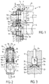
- Figure 1 is a partial vertical sectional view of a rotary cutting apparatus according to the invention, in the position in which it is stationary, before a work time.
- Figure 2 is a vertical sectional view taken along the line II-II of figure 1.
- Figure 3 is a partial sectional view, to a larger ladder, of an embodiment of a back pressure stop with elastic support, in the position it occupies after a certain period of work of the device.
- the rotary cutting device which is partially shown in Figure 1, includes a frame consisting of two uprights parallel lateral 1, interconnected by crosspieces horizontal not shown. One side of the device is shown in Figure 1, the other side being symmetrical from the previous one. Each amount 1 is notched, in its part upper, of an opening 3 extending vertically, of rectangular shape and opening into the horizontal face higher of the amount.
- an interchangeable cutting device consisting of basically two upper cutting cylinders 4 and lower 5, with parallel horizontal axes, between which must pass a tablecloth of paper or cardboard to cut.
- the upper cutting cylinder 4 is extended, at each of its ends, by a coaxial rocket 4a, and it is integral with two raceways 4b located at a distance from the two faces fronts of the cutting cylinder 4 and between which is the engraved part of cylinder 4.
- the cylinder of lower cut 5 is extended, at each of its ends, by a coaxial rocket 5a.
- the raceways upper 4b having the same diameter which is slightly higher to that of the upper cutting cylinder 4, roll on the periphery of the lower cylinder 5 if it is smooth by constituting then an "anvil” cylinder, or else on raceways 5b of the lower cylinder if it is also engraved.
- the diameter of the paths rolling bearing 4b is equal to that of the paths lower bearing 5b and to the original diameter of gears 7, 8, respectively linked to rockets 4a, 5a of the cutting cylinders 4, 5, outside the upright 1. These link gears 7, 8 are engaged one with each other and are rotated from the control of the device.
- the rockets 4a and 5a of the cutting cylinders 4, 5 are respectively rotatably mounted in superimposed blocks forming bearings, namely upper and lower bearing blocks 9 10, engaged closely in the openings 3 and capable of sliding vertically in them.
- Each upper bearing block 9 is extended, at its upper part, towards the interior of the device, by a part in overhang 9a extending above the extreme part of the upper cutting cylinder 4.
- each block lower bearing 10 is extended, at its lower part, towards the interior of the device by a cantilever part 10a which extends below the extreme part of the cylinder lower cutting 5 and above a fixed insert stop 11.
- This stop 11 is fixed, by means of screws, to the face internal of the corresponding amount 1 so that its face upper horizontal is located at a level slightly higher than where the lower edge of the opening is 3. Therefore the internal cantilevered part 10a of each lower bearing block 10 is normally supported on the upper face of the insert 11 and the lower face from this lower bearing block 10 is slightly apart from the lower edge of the opening 3.
- a pressurizing frame 12 which includes a cross central unit 13 carrying, at each of its ends, a jack vertical pressurization 14.
- the rod of this jack extends down, and its lower end is located just above the cantilever part 9a of the bearing block upper 9 and in contact with it.
- Each vertical pressurizing cylinder 14 is mounted on the cross member 13 of the pressurizing frame 12, such so that the vertical axis of the jack 14 is contained in a vertical and transverse plane P passing through the lower stop 11 and located between the vertical and transverse plane median P1 of the neighboring upper raceway 4b and the neighboring upper bearing block 9.
- At least one counterpressure stop 15, integral of the upper bearing block 9, of adjustable height, is interposed between each pair of upper bearing blocks 9 and lower 10.
- This back pressure stop 15 is located substantially in the vertical and transverse median plane P2 common to the two upper 9 and lower 10 bearing blocks of the same pair of blocks.
- Means are provided to adjust, as desired, the height of the adjustable back pressure stop (s) 15.
- These means may include, for example, two vertical rods 16, crossing from top to bottom each upper bearing block 9, on either side of the spindle 4a of the upper cutting cylinder 4, and of which at least the lower parts 16a are threaded and screwed into corresponding tapped holes provided in the lower part of the upper block 9.
- the two parts lower 16a rods 16 constitute the back pressure stop 15 supported by their lower front faces, on the upper face of the lower bearing block 10.
- the two rods 16 are integral of respective pinions 17 engaged with a pinion common central 18 secured to a vernier 19. It is thus possible, by turning this vernier 19, to adjust the height of which the lower parts 16a of the rods 16 make projection below the bearing block 9 and consequently the spacing between the two blocks 9 and 10.
- the pressurizing frame 12 When the rotary cutting device is pressurized, the pressurizing frame 12 extends horizontally and when each cylinder 14 is put under pressure, its rod is pushed down, against the bearing block upper 9.
- the force F produced by the jack 14 is exerted towards the bottom in the vertical and transverse plane P passing through the axis of the corresponding jack 14 and it is collected by the fixed stop 11.
- the external pressure force F directed downwards, opposes a first reaction force F1, directed upwards, acting between the raceways 4b and 5b and at a second reaction or back pressure force F2, directed upwards, acting between the two rockets 4a and 5a and tending to separate them from each other.
- Such a built-in device for the rocket 4a operates satisfactorily at the start of a shift but after a while, the cutting cylinder 4 and the anvil cylinder 5 heats up and the resulting expansion causes a separation of the axes of these two cylinders 4 and 5.
- This spacing is easily absorbed by the vertical cylinder 14 whose stem retracts somewhat, but because the axis of the upper cutting cylinder 4 moves upwards relative to the axis of the lower anvil cylinder 5 maintained fixed, each upper bearing 9 moves upwards by relative to the lower bearing 10 remaining fixed and the front face lower of back pressure stop 15 deviates from the upper support face of the lower bearing block 10, if although this back pressure stop no longer plays its role and that the backpressure force F2 decreases.
- This elastic means 21 which can be composed, for example, Belleville washers or an elastomer block, is housed in a recess 22 formed in the upper face of the block lower bearing 10.
- the elastic means 21 bears on the bottom 23 of hollow 22, bottom to which is applied normally the lower front face 16b of each rod 26.
- the threaded lower part 16a of each rod 16 is extended downwards by an extreme part more small diameter 16c which extends to the front face lower 16b of the rod 16.
- the elastic means 21 (washers Belleville or annular elastomer block) surrounds the extreme part of small diameter 16c and it is in abutment towards the top against the annular shoulder 24 formed between the part lower threaded 16a of the rod 16 and the end part 16b small diameter.
- each rod 16 is adjusted so that its lower front face 16b either in contact with the bottom 23 of the hollow 22, as it is shown in Figures 1 and 2.
- the elastic means 21 is strongly crushed.
- the cutting cylinders 4 and 5 have heated up and dilated and the axis of rotation of the upper cylinder 4 moved upwards, then moving the front side away lower 16b of the back pressure stop 15 23 of the recess 22, as shown in FIG. 3.
- the characteristics of the elastic means 21 are chosen so that this elastic element 21 continues to exert upward reaction or back pressure F2 which allows the installation of the spindle 4a of the upper cutting cylinder 4. Therefore the initial setting happens to be kept practically constant whatever the temperature of the cutting cylinders.
Landscapes
- Engineering & Computer Science (AREA)
- Mechanical Engineering (AREA)
- Life Sciences & Earth Sciences (AREA)
- Forests & Forestry (AREA)
- Perforating, Stamping-Out Or Severing By Means Other Than Cutting (AREA)
- Details Of Cutting Devices (AREA)
Description
Claims (6)
- Appareil de découpage rotatif comprenant un bâti supportant entre deux montants verticaux parallèles (1), deux cylindres de coupe superposés (4, 5), d'axes parallèles, à savoir un cylindre de coupe supérieur (4) et un cylindre de coupe inférieur (5) respectivement solidaires de chemins de. roulement (4b, 5b) roulant les uns sur les autres, chaque cylindre de coupe (4, 5) comportant à chaque extrémité une fusée coaxiale (4a, 5a) montée à rotation dans un bloc palier (9, 10) pouvant coulisser verticalement sur les deux montants respectifs (1), chacun des blocs paliers supérieurs (9) étant prolongé à sa partie supérieure, vers l'intérieur de l'appareil, par une partie en porte-à-faux (9a) soumise à l'action, vers le bas, d'un vérin vertical de mise en pression (14) monté à la partie supérieure de l'appareil, tandis que chacun des blocs paliers inférieurs (10) est prolongé, à sa partie inférieure, vers l'intérieur de l'appareil, par une partie en porte-à-faux (10a) s'étendant au-dessus d'une butée (11) portée par le montant correspondant (1) et avec laquelle elle est en contact, un dispositif d'accouplement étant prévu entre chaque paire de blocs paliers supérieur (9) et inférieur (10) comprenant un moyen élastique (21) travaillant en compression tendant à soulever le bloc palier supérieur par rapport au bloc palier inférieur et autorisant une course verticale limitée du bloc palier supérieur par rapport au bloc palier inférieur, le dispositif d'accouplement comprenant en outre une butée de contre-pression (15) solidaire du bloc palier supérieur (9) et pouvant s'appuyer sur le bloc palier inférieur (10) lorsque le moyen élastique est comprimé, les axes d'action des moyens élastiques (21) et des butées de contre-pression étant écartés des axes des vérins de mise en pression (14) de manière que ces axes d'action se trouvent à l'extérieur des axes des vérins de mise en pression (14), caractérisé en ce que les caractéristiques du moyen élastique (21) sont choisies de telle façon que ce moyen élastique exerce constamment vers le haut, même après un écartement des butées de contre-pression des blocs palier inférieurs à cause d'un échauffement et dilatation des cylindres, une force de réaction F2 suffisante pour assurer en permanence l'encastrement de la fusée (4a) du cylindre de coupe supérieur (4) quelle que soit la température des cylindres de coupe (4, 5).
- Appareil suivant la revendication 1, caractérisé en ce que le moyen élastique (21) prend appui sur le fond (23) d'un creux (22) formé dans la face supérieure du bloc palier inférieur (10).
- Appareil suivant l'une des revendications 1 ou 2 caractérisé en ce que la butée de contre-pression (15) est constituée par la partie inférieure (16a) d'une tige (16) de réglage de la hauteur de la butée, la partie inférieure (16a) de la tige (16) est prolongée vers le bas par une partie extrême de plus petit diamètre (16c), en délimitant entre elles un épaulement annulaire (24), et le moyen élastique (21) entoure la partie extrême de petit diamètre (16c) et est en butée vers le haut contre l'épaulement annulaire (24).
- Appareil suivant l'une des revendications 1 à 3, caractérisé en ce que le moyen élastique (21) est constitué par des rondelles Belleville ou un bloc d'élastomère annulaire entourant la partie extrême de petit diamètre (16c) de la tige (16).
- Appareil suivant l'une des revendications 1 à 4, caractérisé en ce que chaque vérin de mise en pression (14) est monté de telle façon que l'axe vertical du vérin (14) soit contenu dans un plan vertical et transversal (P) passant par la butée (11) et situé entre le plan vertical et transversal médian (P1) du chemin de roulement supérieur voisin (4b) et le bloc palier supérieur voisin (9).
- Appareil suivant l'une des revendications 1 à 5, caractérisé en ce que la butée de contre-pression (15) est située sensiblement dans le plan vertical et transversal médian (P2) commun aux deux blocs paliers supérieur (9) et inférieur (10) d'une même paire de blocs.
Applications Claiming Priority (2)
| Application Number | Priority Date | Filing Date | Title |
|---|---|---|---|
| FR9301520 | 1993-02-11 | ||
| FR9301520A FR2701419B1 (fr) | 1993-02-11 | 1993-02-11 | Appareil de découpage rotatif. |
Publications (2)
| Publication Number | Publication Date |
|---|---|
| EP0611187A1 EP0611187A1 (fr) | 1994-08-17 |
| EP0611187B1 true EP0611187B1 (fr) | 1998-04-15 |
Family
ID=9443947
Family Applications (1)
| Application Number | Title | Priority Date | Filing Date |
|---|---|---|---|
| EP94400224A Expired - Lifetime EP0611187B1 (fr) | 1993-02-11 | 1994-02-03 | Appareil de découpage rotatif |
Country Status (3)
| Country | Link |
|---|---|
| EP (1) | EP0611187B1 (fr) |
| DE (2) | DE611187T1 (fr) |
| FR (1) | FR2701419B1 (fr) |
Families Citing this family (5)
| Publication number | Priority date | Publication date | Assignee | Title |
|---|---|---|---|---|
| CH693824A5 (fr) * | 1999-04-28 | 2004-02-27 | Bobst Sa | Dispositif de fixation et de guidage d'un palier sur un bâti. |
| DE102005022604A1 (de) * | 2005-05-11 | 2006-11-16 | Aichele Werkzeuge Gmbh | Rotationsschneidvorrichtung, Verfahren zur Außerbetriebnahme einer Rotationsschneidvorrichtung und Verfahren zum Betrieb einer Rotationsschneidvorrichtung |
| CN101712163B (zh) * | 2009-11-18 | 2012-07-18 | 佛山市南海富利包装机械有限公司 | 一种螺旋横切机刀轴结构 |
| CN102825630B (zh) * | 2012-08-29 | 2015-09-16 | 三明市普诺维机械有限公司 | 高速辊压模切刀模架 |
| GB201703644D0 (en) | 2017-03-07 | 2017-04-19 | Elopak As | Improvements in or relating to toller mounting arrangements |
Family Cites Families (7)
| Publication number | Priority date | Publication date | Assignee | Title |
|---|---|---|---|---|
| DE683058C (de) * | 1937-05-01 | 1939-10-28 | Alfred Winkler | Einrichtung an Papierschneidwalzen, die mit harten Gegenwalzen arbeiten |
| GB1114778A (en) * | 1965-09-17 | 1968-05-22 | Loewy Eng Co Ltd | Pre-stressed rolling mill |
| DE2750530A1 (de) * | 1977-11-11 | 1979-05-17 | Winkler Duennebier Kg Masch | Rotationsstanze zum ausstanzen von formschnitten |
| US4553461A (en) * | 1982-10-12 | 1985-11-19 | Magna-Graphics Corporation | Rotary web processing apparatus |
| DE3606147C1 (de) * | 1986-02-26 | 1987-06-25 | Ibsm Mehltretter Gmbh | Vorrichtung zur Aufnahme von scherenartig zusammenwirkenden,kreisfoermigen Schneidwerkzeugen |
| FR2645790A1 (fr) * | 1989-03-30 | 1990-10-19 | Umat | Appareil de decoupage rotatif |
| DE4037110A1 (de) * | 1990-11-22 | 1992-05-27 | Goebel Gmbh Maschf | Einrichtung zum aendern des arbeitspunktes |
-
1993
- 1993-02-11 FR FR9301520A patent/FR2701419B1/fr not_active Expired - Fee Related
-
1994
- 1994-02-03 EP EP94400224A patent/EP0611187B1/fr not_active Expired - Lifetime
- 1994-02-03 DE DE0611187T patent/DE611187T1/de active Pending
- 1994-02-03 DE DE69409556T patent/DE69409556T2/de not_active Expired - Lifetime
Also Published As
| Publication number | Publication date |
|---|---|
| DE69409556D1 (de) | 1998-05-20 |
| FR2701419A1 (fr) | 1994-08-19 |
| FR2701419B1 (fr) | 1995-05-05 |
| DE611187T1 (de) | 1995-05-18 |
| EP0611187A1 (fr) | 1994-08-17 |
| DE69409556T2 (de) | 1998-09-24 |
Similar Documents
| Publication | Publication Date | Title |
|---|---|---|
| EP0390689B1 (fr) | Appareil de découpage rotatif | |
| CH615864A5 (fr) | ||
| EP0547954B1 (fr) | Appareil de découpage rotatif | |
| EP0383704A1 (fr) | Dispositif d'entraînement de matériaux en bande, en plaque ou en fil | |
| FR2587266A1 (fr) | Machine a couper le pain en tranches | |
| FR2672542A1 (fr) | Dispositif de detection, dans une machine, de la position de contact de deux cylindres d'axes paralleles. | |
| FR2674787A1 (fr) | Machine de coupe et table de reception combinees. | |
| EP0611187A1 (fr) | Appareil de découpage rotatif | |
| CH630291A5 (fr) | Imprimeuse rotative pour l'impression en plusieurs couleurs sur des feuilles debitees d'une maniere continue. | |
| EP0564372B1 (fr) | Appareil d'impression offset | |
| EP0451667A1 (fr) | Dispositif de séparation des poses dans une machine de travail d'éléments en plaque ou feuilles en vue de la production d'emballages | |
| EP0260178B1 (fr) | Machine d'impression pour impression sur surface convexe | |
| EP0747148B1 (fr) | Unité de présertissage et de sertissage du bord d'une tôle | |
| CH392385A (fr) | Dispositif transporteur pour machine à fa^conner des pièces de métal | |
| FR2629448A1 (fr) | Appareillage pour decouper une piece en un materiau du type verre ou ceramique le long d'une ligne incisee | |
| EP0564360B1 (fr) | Appareil d'impression offset | |
| EP0642461B1 (fr) | Dispositif de redressement d'une nappe de matiere, par exemple de carton, defilant en continu | |
| FR2640175A1 (fr) | Dispositif de sciage | |
| FR2490125A1 (fr) | Dispositif pour le reglage du jeu des lames d'une cisaille guillotine | |
| FR2584334A1 (fr) | Machine a decouper les feuilles minces en disques | |
| FR2647052A1 (fr) | Machine pour le pliage de feuilles de matiere thermoplastique | |
| LU83200A1 (fr) | Appareil de distribution de produits en rouleaux,notamment d'essuie-mains en papier | |
| FR2625946A1 (fr) | Installation de fabrication et d'empilage de sacs, sachets, etc. en matiere thermoplastique | |
| CH424518A (fr) | Machine à boucher les bouteilles | |
| FR2717109A1 (fr) | Dispositif de pliage d'une tôle le long d'une ligne droite. |
Legal Events
| Date | Code | Title | Description |
|---|---|---|---|
| PUAI | Public reference made under article 153(3) epc to a published international application that has entered the european phase |
Free format text: ORIGINAL CODE: 0009012 |
|
| 17P | Request for examination filed |
Effective date: 19940207 |
|
| AK | Designated contracting states |
Kind code of ref document: A1 Designated state(s): CH DE GB IT LI NL |
|
| GBC | Gb: translation of claims filed (gb section 78(7)/1977) | ||
| TCNL | Nl: translation of patent claims filed | ||
| DET | De: translation of patent claims | ||
| 17Q | First examination report despatched |
Effective date: 19960528 |
|
| GRAG | Despatch of communication of intention to grant |
Free format text: ORIGINAL CODE: EPIDOS AGRA |
|
| GRAG | Despatch of communication of intention to grant |
Free format text: ORIGINAL CODE: EPIDOS AGRA |
|
| GRAH | Despatch of communication of intention to grant a patent |
Free format text: ORIGINAL CODE: EPIDOS IGRA |
|
| RAP1 | Party data changed (applicant data changed or rights of an application transferred) |
Owner name: SOCIETE D'ETUDE DE MACHINES POUR LES ARTS GRAPHIQU |
|
| GRAH | Despatch of communication of intention to grant a patent |
Free format text: ORIGINAL CODE: EPIDOS IGRA |
|
| GRAA | (expected) grant |
Free format text: ORIGINAL CODE: 0009210 |
|
| AK | Designated contracting states |
Kind code of ref document: B1 Designated state(s): CH DE GB IT LI NL |
|
| REG | Reference to a national code |
Ref country code: CH Ref legal event code: EP |
|
| ITF | It: translation for a ep patent filed | ||
| REG | Reference to a national code |
Ref country code: CH Ref legal event code: NV Representative=s name: TROESCH SCHEIDEGGER WERNER AG |
|
| GBT | Gb: translation of ep patent filed (gb section 77(6)(a)/1977) |
Effective date: 19980417 |
|
| REF | Corresponds to: |
Ref document number: 69409556 Country of ref document: DE Date of ref document: 19980520 |
|
| PLBE | No opposition filed within time limit |
Free format text: ORIGINAL CODE: 0009261 |
|
| STAA | Information on the status of an ep patent application or granted ep patent |
Free format text: STATUS: NO OPPOSITION FILED WITHIN TIME LIMIT |
|
| 26N | No opposition filed | ||
| REG | Reference to a national code |
Ref country code: GB Ref legal event code: IF02 |
|
| PGFP | Annual fee paid to national office [announced via postgrant information from national office to epo] |
Ref country code: CH Payment date: 20110330 Year of fee payment: 18 Ref country code: IT Payment date: 20110323 Year of fee payment: 18 Ref country code: NL Payment date: 20110330 Year of fee payment: 18 |
|
| PGFP | Annual fee paid to national office [announced via postgrant information from national office to epo] |
Ref country code: DE Payment date: 20110427 Year of fee payment: 18 Ref country code: GB Payment date: 20110331 Year of fee payment: 18 |
|
| REG | Reference to a national code |
Ref country code: NL Ref legal event code: V1 Effective date: 20120901 |
|
| REG | Reference to a national code |
Ref country code: CH Ref legal event code: PL |
|
| GBPC | Gb: european patent ceased through non-payment of renewal fee |
Effective date: 20120203 |
|
| PG25 | Lapsed in a contracting state [announced via postgrant information from national office to epo] |
Ref country code: LI Free format text: LAPSE BECAUSE OF NON-PAYMENT OF DUE FEES Effective date: 20120229 Ref country code: CH Free format text: LAPSE BECAUSE OF NON-PAYMENT OF DUE FEES Effective date: 20120229 |
|
| PG25 | Lapsed in a contracting state [announced via postgrant information from national office to epo] |
Ref country code: IT Free format text: LAPSE BECAUSE OF NON-PAYMENT OF DUE FEES Effective date: 20120203 |
|
| REG | Reference to a national code |
Ref country code: DE Ref legal event code: R119 Ref document number: 69409556 Country of ref document: DE Effective date: 20120901 |
|
| PG25 | Lapsed in a contracting state [announced via postgrant information from national office to epo] |
Ref country code: GB Free format text: LAPSE BECAUSE OF NON-PAYMENT OF DUE FEES Effective date: 20120203 Ref country code: NL Free format text: LAPSE BECAUSE OF NON-PAYMENT OF DUE FEES Effective date: 20120901 |
|
| PG25 | Lapsed in a contracting state [announced via postgrant information from national office to epo] |
Ref country code: DE Free format text: LAPSE BECAUSE OF NON-PAYMENT OF DUE FEES Effective date: 20120901 |