EP0610891A2 - Mécanisme d'ajustement de la hauteur de sertissage - Google Patents
Mécanisme d'ajustement de la hauteur de sertissage Download PDFInfo
- Publication number
- EP0610891A2 EP0610891A2 EP94101906A EP94101906A EP0610891A2 EP 0610891 A2 EP0610891 A2 EP 0610891A2 EP 94101906 A EP94101906 A EP 94101906A EP 94101906 A EP94101906 A EP 94101906A EP 0610891 A2 EP0610891 A2 EP 0610891A2
- Authority
- EP
- European Patent Office
- Prior art keywords
- threaded portion
- ram
- axis
- adjustment mechanism
- anvil
- Prior art date
- Legal status (The legal status is an assumption and is not a legal conclusion. Google has not performed a legal analysis and makes no representation as to the accuracy of the status listed.)
- Granted
Links
Images


Classifications
-
- H—ELECTRICITY
- H01—ELECTRIC ELEMENTS
- H01R—ELECTRICALLY-CONDUCTIVE CONNECTIONS; STRUCTURAL ASSOCIATIONS OF A PLURALITY OF MUTUALLY-INSULATED ELECTRICAL CONNECTING ELEMENTS; COUPLING DEVICES; CURRENT COLLECTORS
- H01R43/00—Apparatus or processes specially adapted for manufacturing, assembling, maintaining, or repairing of line connectors or current collectors or for joining electric conductors
- H01R43/04—Apparatus or processes specially adapted for manufacturing, assembling, maintaining, or repairing of line connectors or current collectors or for joining electric conductors for forming connections by deformation, e.g. crimping tool
- H01R43/048—Crimping apparatus or processes
- H01R43/0488—Crimping apparatus or processes with crimp height adjusting means
-
- Y—GENERAL TAGGING OF NEW TECHNOLOGICAL DEVELOPMENTS; GENERAL TAGGING OF CROSS-SECTIONAL TECHNOLOGIES SPANNING OVER SEVERAL SECTIONS OF THE IPC; TECHNICAL SUBJECTS COVERED BY FORMER USPC CROSS-REFERENCE ART COLLECTIONS [XRACs] AND DIGESTS
- Y10—TECHNICAL SUBJECTS COVERED BY FORMER USPC
- Y10T—TECHNICAL SUBJECTS COVERED BY FORMER US CLASSIFICATION
- Y10T29/00—Metal working
- Y10T29/49—Method of mechanical manufacture
- Y10T29/49002—Electrical device making
- Y10T29/49117—Conductor or circuit manufacturing
- Y10T29/49174—Assembling terminal to elongated conductor
- Y10T29/49181—Assembling terminal to elongated conductor by deforming
- Y10T29/49185—Assembling terminal to elongated conductor by deforming of terminal
-
- Y—GENERAL TAGGING OF NEW TECHNOLOGICAL DEVELOPMENTS; GENERAL TAGGING OF CROSS-SECTIONAL TECHNOLOGIES SPANNING OVER SEVERAL SECTIONS OF THE IPC; TECHNICAL SUBJECTS COVERED BY FORMER USPC CROSS-REFERENCE ART COLLECTIONS [XRACs] AND DIGESTS
- Y10—TECHNICAL SUBJECTS COVERED BY FORMER USPC
- Y10T—TECHNICAL SUBJECTS COVERED BY FORMER US CLASSIFICATION
- Y10T29/00—Metal working
- Y10T29/53—Means to assemble or disassemble
- Y10T29/5313—Means to assemble electrical device
- Y10T29/532—Conductor
- Y10T29/53209—Terminal or connector
- Y10T29/53213—Assembled to wire-type conductor
- Y10T29/53235—Means to fasten by deformation
Definitions
- the invention relates to a crimp height adjustment mechanism according to the preamble of claim 1.
- the invention relates to a machine for crimping a terminal to an electrical conductor, and more particularly, to a mechanism which enables extremely fine adjustment of the height of a crimped terminal produced in such a machine.
- Machines for crimping a terminal to an electrical conductor such as a wire or cable.
- Such machines generally employ a ram which is reciprocally movable with respect to a fixed anvil.
- the ram carries a crimping die which cooperates with the anvil to crimp a terminal therebetween.
- the ram is driven through a working stroke to deform the terminal and tightly engage the conductor within the terminal to form a crimped connection.
- the crimp height i.e., the height or vertical dimension of the terminal after deformation, is a good indicator of quality of the crimped connection.
- the terminal In order to produce a secure and reliable crimped connection, the terminal must be deformed around the conductor until the height of the terminal is below a certain maximum. Terminals and conductors come in a variety of types and sizes, and the maximum is predetermined for many different combinations of terminals and conductors. Based on pullout tests which measure the tension required to separate crimped terminals of various crimp heights from their associated conductors, the maximum crimp height for a particular combination of terminal and conductor can be calculated. Ideal crimp heights are somewhat below the maximum so as to provide a safety factor against pullout while avoiding excessive deformation of the terminal which may in itself destroy the crimped connection and requires greater energy to produce.
- a crimping machine which has been set up to produce a certain crimp height may require adjustment after some time in operation.
- the need for adjustment may be due to wear of components in the machine, non-uniformity of terminals being crimped, or a change in the type or size of the terminal or conductor.
- Various mechanisms for adjusting crimp height are known. These mechanisms provide either a means to vary the working stroke of the ram or a means to adjust a rest position of the ram with respect to the anvil, thereby adjusting a dimension from the crimping die to the anvil when the ram is at the fullest extent of its working stroke.
- the known adjustment mechanisms are somewhat coarse, generally being unable to achieve crimp height adjustments in increments smaller than .001 inch.
- the invention provides a crimp height adjustment mechanism as defined in claim 1. Preferred embodiments thereof are defined in the dependent claims.
- a crimp height adjustment mechanism for use in a crimping machine having an anvil and a ram carrying a crimping die.
- the ram is secured against rotation and guided for reciprocal movement along a ram axis for moving the crimping die toward and away from the anvil between remote and proximate positions with respect to the anvil.
- the crimping die is adapted to cooperate with the anvil for crimping a terminal when the crimping die is in the proximate position, and a drive member connected for reciprocating the ram.
- the adjustment mechanism is characterized by: a first member fixed with respect to the anvil and having a first threaded portion extending along an adjustment axis parallel to the ram axis, the first threaded portion having a first thread pitch; a second member having a second threaded portion which is coaxial to the first threaded portion, the second threaded portion having a second thread pitch which differs from the first thread pitch, the second member being secured against rotation and coupled to the ram such that linear movement of the second member along the adjustment axis produces a corresponding linear movement of the ram along the ram axis; and a third member having both a third threaded portion which is adjustably threadedly engaged with the first threaded portion, and a fourth threaded portion which is adjustably threadedly engaged with the second threaded portion, the third member being rotatable about the adjustment axis so as to change an extent of engagement with the first and second threaded portions, the third member having actuation means enabling adjustable movement thereof.
- Actuating rotation of the third member about the adjustment axis produces a linear movement of the second member which is equal to a number of rotations of the third member multiplied by a difference between the first and second pitches.
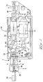
- a crimp height adjustment mechanism is shown generally as 4 in use on a crimping machine having a frame 58 which supports an anvil 42 and a ram 44 carrying a crimping die 46 at one end.
- the ram is guided for reciprocal movement along a ram axis R-R for moving the crimping die toward and away from the anvil between remote and proximate positions with respect to the anvil.
- the ram has a rectangular cross-section and is disposed in a ramway of guideframe 92 of the machine frame 58.
- the guideframe 92 ramway guides the ram during its reciprocal movement and also secures the ram against rotation about the axis R-R.
- the crimp height adjustment mechanism of the present invention is equally well-suited for use with others of those arrangements.
- the crimping machine further includes a drive member such as extensible cylinder 52 which is connected via bellcrank 66 and toggle link 68 for reciprocating the ram 44 and moving the crimping die 46 between the remote and proximate positions.
- the extensible cylinder 52 is operable via air or hydraulic forces received through connections (not shown) to extend or retract cylinder rod 54.
- One end of the cylinder 52 is connected by pivot pin 62 to the machine frame 58.
- the rod 54 is pivotally connected by clevis 72 with the bellcrank 66, which in turn has a pivotal connection 74 with the adjustment mechanism 4.
- the pivotal connection 74 which acts as a fulcrum for the bellcrank 66, is generally fixedly disposed during stroking of the cylinder 52, being linearly movable only during occasions of crimp height adjustment between strokes of the cylinder 52.
- the toggle link 68 has pivotal connections 76, 78 with the bellcrank 66 and the ram 44, respectively, thus completing a connection for reciprocating the ram 44 upon actuation of the cylinder 52.
- other types of drive members and other arrangements for connecting a drive member to reciprocate the ram will be readily apparent to those skilled in the art and are considered to be within the scope of the invention.
- the crimping die 46 is adapted to cooperate with the anvil 42 to crimp a terminal (not shown) onto a conductor when the crimping die is in the proximate position.
- the crimp height adjustment mechanism 4 of the present invention is housed in a retainer 6 which is attached to the machine frame 58 by retainer key 86 extending through slot 38 in the retainer 6.
- a first member 10 comprises a hub that is fixed within the retainer 6.
- the hub 10 has longitudinal splines 16 around its outer periphery, and a setscrew 18 threaded in the retainer 6 engages between two of the splines 16 and prevents rotation of the hub within the retainer.
- the hub 10 has a central bore 14 extending along an adjustment axis A-A which is parallel to the ram axis R-R.
- a wall of the central bore 14 defines screw threads which provide a first threaded portion 12 having a first thread pitch which is preselected as will be more fully described hereinafter.
- the adjustment axis A-A of the adjustment mechanism 4 is coincident with the ram axis R-R.
- a second member 20 comprises a yoke shaft having a yoke 26 at one end which receives the pivotal connection 74 within holes 28 for joining with the bellcrank 66.
- the yoke shaft 20 is secured against rotation about the adjustment axis A-A by engagement of the yoke 26 in the guideframe 92 ramway.
- An other end of the yoke shaft 20 is threaded so as to define a second threaded portion 22 which is coaxial to the first threaded portion 12.
- the second threaded portion 22 has a second thread pitch which is selected to be different from the first thread pitch.
- the yoke shaft 20 is coupled to the ram 44 through the bellcrank 66 and the toggle link 68 such that linear movement of the second member 20 along the adjustment axis A-A produces a corresponding linear movement of the ram along the ram axis R-R.
- a third member 30 comprises an adjuster shaft having an external periphery and a coaxial bore.
- the external periphery defines a third threaded portion 32 which is threadedly engaged with the first threaded portion 12 of the hub 10.
- the wall of the coaxial bore defines a fourth threaded portion 34 which is threadedly engaged with the second threaded portion 22 of the yoke shaft 20.
- the threaded engagement is loosely adjustable, i.e., the adjuster shaft 30 is rotatable about the adjustment axis A-A within the hub 10 and on the yoke shaft 20. Rotation of the adjuster shaft 30 causes an increase or decrease in the extent of engagement with the first threaded portion 12 and the second threaded portion 22.
- each of the first, second, third and fourth threaded portions comprises right hand screw threads, i.e., clockwise rotation of the adjuster shaft produces forward movement thereof.
- clockwise rotation of the adjuster shaft 30 results in increasing engagement between the first threaded portion 12 and the third threaded portion 32.
- one rotation of the adjuster shaft 30 results in linear movement of the adjuster shaft to the right over a distance equal to the first thread pitch.
- the fourth threaded portion 34 increasingly engages with the second threaded portion 22.
- one rotation of the adjuster shaft 30 results in linear movement of the yoke shaft 20 over a distance equal to the difference between the first and second pitches.
- first thread pitch 12 is greater than the second thread pitch 22
- clockwise rotation of the adjuster shaft 30 results in right hand movement of the yoke shaft 20.
- counter-clockwise rotation of the adjuster shaft 30 results in left hand movement of the yoke shaft 20.
- the first and second pitches are selected so that a difference between them is quite small.
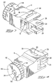
- Actuation means enabling rotatable movement of the adjuster shaft 30 includes a manually gripable adjustment wheel 48.
- the wheel 48 has a groove 94 which allows passage for a drive pin 56 coupled to the adjuster shaft 30 which engages with a cap 88 or a motor coupler 96 and is secured with screw 98 for rotating the adjuster shaft.
- circumferential surface 82 of the adjustment wheel 48 has alignment marks 84 at regular intervals, as shown in Figure 7.
- the adjuster shaft 30 can be rotated in precise steps in order to effect precise changes in crimp height.
- the first thread pitch is 14 threads per inch (.0714 inch) and the second thread pitch is 18 threads per inch (.0555 inch).
- the difference between the first and second pitches is approximately .016 inch.
- the surface 82 of the adjustment wheel 48 has 32 of the marks 84 spaced at regular intervals 11.25 degrees apart around the circumference thereof. It is very easy to rotate the adjustment wheel 48 through an interval of 11.25 degrees to change alignment from one mark 84 to the next. Such a rotation of the adjustment wheel effects a change in crimp height of .0005 inch, with more precision and repeatability than prior devices for changing crimp height.
- the actuation means may also include, either in addition to or in place of the adjustment wheel 48, an automatic means such as adjuster motor 64, shown in Figure 1, which is connected for rotating the adjuster shaft 30 in response to a signal from a sensor (not shown).
- the adjuster motor 64 can be electrically connected to a crimp height monitor such as that disclosed in U.S. Patent No. 4,856,186 or U.S Patent No. 4,916,810, both of which are incorporated by reference as if fully set forth herein.
- the motor 64 can be programmed to make automatic crimp height adjustments when the crimp height monitor detects crimps that are out of specification.
- the adjuster motor can be programmed to make a sequence of adjustments in order to perform a sequence of crimping operations requiring different crimp heights.
- first, second, third and fourth threaded portions 12, 22, 32 and 34 be at least partly concentric in order to provide a compact arrangement for the crimp height adjustment mechanism.
Landscapes
- Engineering & Computer Science (AREA)
- Manufacturing & Machinery (AREA)
- Manufacturing Of Electrical Connectors (AREA)
Applications Claiming Priority (2)
| Application Number | Priority Date | Filing Date | Title |
|---|---|---|---|
| US08/015,750 US5228326A (en) | 1993-02-09 | 1993-02-09 | Crimp height adjustment mechanism |
| US15750 | 1993-02-09 |
Publications (3)
| Publication Number | Publication Date |
|---|---|
| EP0610891A2 true EP0610891A2 (fr) | 1994-08-17 |
| EP0610891A3 EP0610891A3 (fr) | 1995-08-16 |
| EP0610891B1 EP0610891B1 (fr) | 1998-12-09 |
Family
ID=21773395
Family Applications (1)
| Application Number | Title | Priority Date | Filing Date |
|---|---|---|---|
| EP94101906A Expired - Lifetime EP0610891B1 (fr) | 1993-02-09 | 1994-02-08 | Mécanisme d'ajustement de la hauteur de sertissage |
Country Status (5)
| Country | Link |
|---|---|
| US (1) | US5228326A (fr) |
| EP (1) | EP0610891B1 (fr) |
| JP (1) | JPH06243950A (fr) |
| BR (1) | BR9400444A (fr) |
| DE (1) | DE69415051T2 (fr) |
Cited By (1)
| Publication number | Priority date | Publication date | Assignee | Title |
|---|---|---|---|---|
| DE19840275C2 (de) * | 1997-09-04 | 2002-08-14 | Yazaki Corp | Verfahren zum Überwachen der Verbindungsqualität einer Crimpverbindung zwischen einem elektrischen Leiter eines Kabels und einer Metallanschlußklemme sowie Anschlußklemme |
Families Citing this family (11)
| Publication number | Priority date | Publication date | Assignee | Title |
|---|---|---|---|---|
| US5645170A (en) * | 1995-04-28 | 1997-07-08 | The Whitaker Corporation | Tape packaging system for electrical terminals |
| JP3156841B2 (ja) * | 1996-06-12 | 2001-04-16 | 矢崎総業株式会社 | 端子圧着装置の制御方法 |
| US5909913A (en) * | 1996-09-19 | 1999-06-08 | The Whitaker Corporation | Shut height adjustment mechanism for a terminal applicator |
| US5937510A (en) * | 1997-07-30 | 1999-08-17 | The Whitaker Corporation | Shut height adjustment mechanism for a terminal applicator |
| US5894658A (en) * | 1997-07-31 | 1999-04-20 | The Whitaker Corporation | Terminal applicator having ram retention feature |
| US5845528A (en) * | 1997-10-07 | 1998-12-08 | Artos Engineering Company | Apparatus for crimping terminals on an electrical conductor |
| US7562552B2 (en) | 2005-11-10 | 2009-07-21 | Tyco Electronics Corporation | Crimp height adjustment mechanism |
| US7797979B2 (en) * | 2006-02-14 | 2010-09-21 | Eaton Corporation | Crimping apparatus including a tool for supporting a plurality of crimping members |
| US7497106B2 (en) * | 2006-02-14 | 2009-03-03 | Eaton Corporation | Crimping apparatus with a support structure including first and second portions |
| CN107942551A (zh) * | 2017-12-23 | 2018-04-20 | 苏州富强科技有限公司 | 用于液晶显示屏压合装置的自适应压头微调机构 |
| CN113300190B (zh) * | 2021-04-30 | 2023-01-24 | 东莞联鹏智能装备有限公司 | 压头调平装置 |
Citations (3)
| Publication number | Priority date | Publication date | Assignee | Title |
|---|---|---|---|---|
| US4707913A (en) * | 1986-09-02 | 1987-11-24 | Artos Engineering Company | Terminal applicator having quick-adjust connecting link |
| WO1988009576A1 (fr) * | 1987-05-29 | 1988-12-01 | Amp Incorporated | Organe de reglage de la hauteur estampe fermee dans une presse |
| US4916810A (en) * | 1989-05-12 | 1990-04-17 | Amp Incorporated | Method and apparatus for terminating wires to terminals |
Family Cites Families (7)
| Publication number | Priority date | Publication date | Assignee | Title |
|---|---|---|---|---|
| US2691911A (en) * | 1953-07-31 | 1954-10-19 | Gren Elmer | Link and lever controlled slidable jaw wrench |
| US3051213A (en) * | 1959-12-11 | 1962-08-28 | Hugh W Batcheller | Adjustable crimping press for various diameters of wires and insulation |
| US3091276A (en) * | 1961-06-19 | 1963-05-28 | Arkles Switch Corp | Crimping apparatus |
| US3335599A (en) * | 1964-09-01 | 1967-08-15 | Maurice M Balsam | Press for stamping frames of a handbag or the like |
| FR2635285B1 (fr) * | 1988-08-12 | 1990-11-23 | Ricard Claude | Procedes et dispositifs pour sertir mecaniquement des terminaux sur des fils conducteurs et pour regler avec precision la hauteur de sertissage |
| US4856186A (en) * | 1988-11-04 | 1989-08-15 | Amp Incorporated | Apparatus and method for determination of crimp height |
| SE464107B (sv) * | 1990-02-05 | 1991-03-04 | Pressmaster Tool Ab | Pressverktyg |
-
1993
- 1993-02-09 US US08/015,750 patent/US5228326A/en not_active Expired - Lifetime
-
1994
- 1994-02-07 BR BR9400444A patent/BR9400444A/pt not_active Application Discontinuation
- 1994-02-08 EP EP94101906A patent/EP0610891B1/fr not_active Expired - Lifetime
- 1994-02-08 DE DE69415051T patent/DE69415051T2/de not_active Expired - Fee Related
- 1994-02-09 JP JP6036550A patent/JPH06243950A/ja active Pending
Patent Citations (3)
| Publication number | Priority date | Publication date | Assignee | Title |
|---|---|---|---|---|
| US4707913A (en) * | 1986-09-02 | 1987-11-24 | Artos Engineering Company | Terminal applicator having quick-adjust connecting link |
| WO1988009576A1 (fr) * | 1987-05-29 | 1988-12-01 | Amp Incorporated | Organe de reglage de la hauteur estampe fermee dans une presse |
| US4916810A (en) * | 1989-05-12 | 1990-04-17 | Amp Incorporated | Method and apparatus for terminating wires to terminals |
Non-Patent Citations (1)
| Title |
|---|
| Book no. , 1989, 'KONSTRUKTIONSELEMENTE DER FEINMECHANIK', KRAUSE, WERNER VEB VERLAG TECHNIK, BERLIN * |
Cited By (2)
| Publication number | Priority date | Publication date | Assignee | Title |
|---|---|---|---|---|
| US6625884B1 (en) | 1997-04-09 | 2003-09-30 | Yazaki Corporation | Method of determining a connection state of metal terminal and a wire |
| DE19840275C2 (de) * | 1997-09-04 | 2002-08-14 | Yazaki Corp | Verfahren zum Überwachen der Verbindungsqualität einer Crimpverbindung zwischen einem elektrischen Leiter eines Kabels und einer Metallanschlußklemme sowie Anschlußklemme |
Also Published As
| Publication number | Publication date |
|---|---|
| DE69415051D1 (de) | 1999-01-21 |
| JPH06243950A (ja) | 1994-09-02 |
| DE69415051T2 (de) | 1999-07-01 |
| US5228326A (en) | 1993-07-20 |
| EP0610891A3 (fr) | 1995-08-16 |
| EP0610891B1 (fr) | 1998-12-09 |
| BR9400444A (pt) | 1994-08-23 |
Similar Documents
| Publication | Publication Date | Title |
|---|---|---|
| US4790173A (en) | Shut height adjustment means in pressing apparatus | |
| US5228326A (en) | Crimp height adjustment mechanism | |
| EP0397434B1 (fr) | Méthode et appareil pour connecter un fil à une borne | |
| EP0459476A2 (fr) | Procédé et appareil pour régler la hauteur de sertissage d'une connexion électrique sertie | |
| US9586283B2 (en) | Wire feeder tensioner with definitive settings | |
| US4707913A (en) | Terminal applicator having quick-adjust connecting link | |
| EP2624992A1 (fr) | Tête à souder dotée d'un capteur de force, d'un ressort et d'un élément de réglage | |
| US20100044409A1 (en) | Method for Determining and Setting Material Release Mechanism Timing for a Material Feed Mechanism | |
| EP1786073B1 (fr) | Dispositif pour le réglage de hauteur de sertissage | |
| EP0892918B1 (fr) | Test d'étanchéité de la fermeture de petits récipients | |
| KR20130029818A (ko) | 단자 압착 기계를 위한 공급 장치 | |
| US20050050940A1 (en) | Crimping apparatus | |
| DE3210889A1 (de) | Schraubvorrichtung | |
| EP0714481B1 (fr) | Dispositif et procede de reglage d'une course de soupape | |
| US4667397A (en) | Electrical lead wire and terminal splicing machine | |
| US6037558A (en) | Integrated low inertia projection welding head and cylinder | |
| JP6300996B1 (ja) | アーク状コイルスプリングの製造方法及び製造装置 | |
| US5483739A (en) | Electrical terminal applicator with improved crimp height adjustment plate means | |
| US5921160A (en) | Release assembly for a wire cutting apparatus | |
| US20100269332A1 (en) | Wire stop for a terminal crimping machine | |
| WO1995032073A1 (fr) | Dispositif de fixation et de guidage d'un element d'assemblage | |
| DE4040410C1 (en) | Tooling for crimping electrical connectors - comprises crank press with spring-loaded plunger, connected torsionally to transducer providing displacement measurement | |
| US5893289A (en) | Machine having crimp height compensation | |
| DE4109795A1 (de) | Verfahren und einrichtung zum stanzen, biegen und/oder pressen | |
| WO1999054092A1 (fr) | Pince a fluide de pression |
Legal Events
| Date | Code | Title | Description |
|---|---|---|---|
| PUAI | Public reference made under article 153(3) epc to a published international application that has entered the european phase |
Free format text: ORIGINAL CODE: 0009012 |
|
| AK | Designated contracting states |
Kind code of ref document: A2 Designated state(s): DE FR GB IT NL |
|
| PUAL | Search report despatched |
Free format text: ORIGINAL CODE: 0009013 |
|
| AK | Designated contracting states |
Kind code of ref document: A3 Designated state(s): DE FR GB IT NL |
|
| 17P | Request for examination filed |
Effective date: 19960215 |
|
| 17Q | First examination report despatched |
Effective date: 19970416 |
|
| GRAG | Despatch of communication of intention to grant |
Free format text: ORIGINAL CODE: EPIDOS AGRA |
|
| GRAG | Despatch of communication of intention to grant |
Free format text: ORIGINAL CODE: EPIDOS AGRA |
|
| GRAH | Despatch of communication of intention to grant a patent |
Free format text: ORIGINAL CODE: EPIDOS IGRA |
|
| GRAH | Despatch of communication of intention to grant a patent |
Free format text: ORIGINAL CODE: EPIDOS IGRA |
|
| GRAA | (expected) grant |
Free format text: ORIGINAL CODE: 0009210 |
|
| AK | Designated contracting states |
Kind code of ref document: B1 Designated state(s): DE FR GB IT NL |
|
| PG25 | Lapsed in a contracting state [announced via postgrant information from national office to epo] |
Ref country code: NL Free format text: LAPSE BECAUSE OF FAILURE TO SUBMIT A TRANSLATION OF THE DESCRIPTION OR TO PAY THE FEE WITHIN THE PRESCRIBED TIME-LIMIT Effective date: 19981209 Ref country code: IT Free format text: LAPSE BECAUSE OF FAILURE TO SUBMIT A TRANSLATION OF THE DESCRIPTION OR TO PAY THE FEE WITHIN THE PRESCRIBED TIME-LIMIT;WARNING: LAPSES OF ITALIAN PATENTS WITH EFFECTIVE DATE BEFORE 2007 MAY HAVE OCCURRED AT ANY TIME BEFORE 2007. THE CORRECT EFFECTIVE DATE MAY BE DIFFERENT FROM THE ONE RECORDED. Effective date: 19981209 |
|
| REF | Corresponds to: |
Ref document number: 69415051 Country of ref document: DE Date of ref document: 19990121 |
|
| ET | Fr: translation filed | ||
| NLV1 | Nl: lapsed or annulled due to failure to fulfill the requirements of art. 29p and 29m of the patents act | ||
| PLBE | No opposition filed within time limit |
Free format text: ORIGINAL CODE: 0009261 |
|
| STAA | Information on the status of an ep patent application or granted ep patent |
Free format text: STATUS: NO OPPOSITION FILED WITHIN TIME LIMIT |
|
| 26N | No opposition filed | ||
| REG | Reference to a national code |
Ref country code: GB Ref legal event code: IF02 |
|
| PGFP | Annual fee paid to national office [announced via postgrant information from national office to epo] |
Ref country code: FR Payment date: 20060217 Year of fee payment: 13 |
|
| PGFP | Annual fee paid to national office [announced via postgrant information from national office to epo] |
Ref country code: GB Payment date: 20060223 Year of fee payment: 13 |
|
| PGFP | Annual fee paid to national office [announced via postgrant information from national office to epo] |
Ref country code: DE Payment date: 20060331 Year of fee payment: 13 |
|
| GBPC | Gb: european patent ceased through non-payment of renewal fee |
Effective date: 20070208 |
|
| REG | Reference to a national code |
Ref country code: FR Ref legal event code: ST Effective date: 20071030 |
|
| PG25 | Lapsed in a contracting state [announced via postgrant information from national office to epo] |
Ref country code: DE Free format text: LAPSE BECAUSE OF NON-PAYMENT OF DUE FEES Effective date: 20070901 |
|
| PG25 | Lapsed in a contracting state [announced via postgrant information from national office to epo] |
Ref country code: GB Free format text: LAPSE BECAUSE OF NON-PAYMENT OF DUE FEES Effective date: 20070208 Ref country code: FR Free format text: LAPSE BECAUSE OF NON-PAYMENT OF DUE FEES Effective date: 20070228 |