EP0610685B1 - Procedure for making a pressure sealed connection of thin-walled articles made of metal - Google Patents
Procedure for making a pressure sealed connection of thin-walled articles made of metal Download PDFInfo
- Publication number
- EP0610685B1 EP0610685B1 EP94100622A EP94100622A EP0610685B1 EP 0610685 B1 EP0610685 B1 EP 0610685B1 EP 94100622 A EP94100622 A EP 94100622A EP 94100622 A EP94100622 A EP 94100622A EP 0610685 B1 EP0610685 B1 EP 0610685B1
- Authority
- EP
- European Patent Office
- Prior art keywords
- enamel layer
- pressure
- thin
- connection
- objects
- Prior art date
- Legal status (The legal status is an assumption and is not a legal conclusion. Google has not performed a legal analysis and makes no representation as to the accuracy of the status listed.)
- Expired - Lifetime
Links
Images
Classifications
-
- B—PERFORMING OPERATIONS; TRANSPORTING
- B23—MACHINE TOOLS; METAL-WORKING NOT OTHERWISE PROVIDED FOR
- B23K—SOLDERING OR UNSOLDERING; WELDING; CLADDING OR PLATING BY SOLDERING OR WELDING; CUTTING BY APPLYING HEAT LOCALLY, e.g. FLAME CUTTING; WORKING BY LASER BEAM
- B23K20/00—Non-electric welding by applying impact or other pressure, with or without the application of heat, e.g. cladding or plating
- B23K20/02—Non-electric welding by applying impact or other pressure, with or without the application of heat, e.g. cladding or plating by means of a press ; Diffusion bonding
- B23K20/023—Thermo-compression bonding
-
- B—PERFORMING OPERATIONS; TRANSPORTING
- B23—MACHINE TOOLS; METAL-WORKING NOT OTHERWISE PROVIDED FOR
- B23K—SOLDERING OR UNSOLDERING; WELDING; CLADDING OR PLATING BY SOLDERING OR WELDING; CUTTING BY APPLYING HEAT LOCALLY, e.g. FLAME CUTTING; WORKING BY LASER BEAM
- B23K20/00—Non-electric welding by applying impact or other pressure, with or without the application of heat, e.g. cladding or plating
- B23K20/16—Non-electric welding by applying impact or other pressure, with or without the application of heat, e.g. cladding or plating with interposition of special material to facilitate connection of the parts, e.g. material for absorbing or producing gas
-
- F—MECHANICAL ENGINEERING; LIGHTING; HEATING; WEAPONS; BLASTING
- F28—HEAT EXCHANGE IN GENERAL
- F28F—DETAILS OF HEAT-EXCHANGE AND HEAT-TRANSFER APPARATUS, OF GENERAL APPLICATION
- F28F19/00—Preventing the formation of deposits or corrosion, e.g. by using filters or scrapers
- F28F19/02—Preventing the formation of deposits or corrosion, e.g. by using filters or scrapers by using coatings, e.g. vitreous or enamel coatings
-
- B—PERFORMING OPERATIONS; TRANSPORTING
- B23—MACHINE TOOLS; METAL-WORKING NOT OTHERWISE PROVIDED FOR
- B23K—SOLDERING OR UNSOLDERING; WELDING; CLADDING OR PLATING BY SOLDERING OR WELDING; CUTTING BY APPLYING HEAT LOCALLY, e.g. FLAME CUTTING; WORKING BY LASER BEAM
- B23K2101/00—Articles made by soldering, welding or cutting
- B23K2101/04—Tubular or hollow articles
- B23K2101/14—Heat exchangers
Definitions
- the invention relates to a method for the pressure-tight connection of thin-walled objects made of metal, in particular plate-shaped sheets, such as heat exchanger plates, which are provided with an enamel layer on at least one side as corrosion protection.
- a method for welding enamelled metal parts is known from EP-OS 0 449 377.
- the metal parts to be welded are welded at the welding point by means of a welding source, such as, for example a laser, heated and welded together. Due to the targeted introduction of heat when using a laser, the enamel layer opposite the welding point is not to be melted in this method, while the base materials of the metal parts to be joined are joined together by melting.
- a welding source such as, for example a laser
- the welding can be carried out from the non-enamelled side, but access to this side is not always guaranteed in the case of complicated and large components, so that a pressure-tight and integral connection of the components to be connected cannot be guaranteed.
- the invention has for its object to provide a method for the pressure-tight connection of thin-walled objects made of metal provided at least on one side with an enamel layer, in which the objects to be connected can be connected to one another without the aid of an additional material and, moreover, the connection point is not subsequently added must be provided with a protective layer.
- the solution to this problem by the invention is characterized in that the objects to be connected to one another are positioned in the correct position and are pressed together at least on the joining surfaces and heated in such a way that the enamel layer located between the joining surfaces changes into a doughy state and causes a material connection of the objects.
- This procedure enables a pressure-tight connection of the thin-walled objects to one another without joining additives and joining means.
- the enamel layer is not heated to the melting point or melting range, but is only brought into a pasty state, which makes it possible for adjacent enamel layers to bond with one another or one enamel layer and one not Connect the enamelled layer so that the enamel penetrates into the surface roughness of the other workpiece as a result of the heat and the applied pressure and bonds to it after cooling.
- the heat and the pressure are applied in a furnace under a normal atmosphere.
- a chamber furnace or a continuous furnace has the advantage that complete structures, such as heat exchanger modules consisting of many individual sheets, can be connected to one another in a single furnace cycle. Since the connection of the objects can take place under a normal atmosphere, the only process parameter to be monitored and controlled is the heating or cooling speed of the furnace.
- the heat required for the connection is generated by inductive heating of the metallic base material of the enamelled, thin-walled objects.
- This inductive heating of the base material heats the enamel layer only indirectly, namely through the base material.
- the objects are connected to each other again by the enamel layer brought into the doughy state, which is due to connects their viscous state and the applied pressure with the other component.
- inductive heating takes place exclusively in the area of the joining surfaces in order to convert the enamel layer into the doughy state only in this area.
- the pressure to be applied is necessary in order to ensure that the surfaces to be connected rest well on one another. In the case of heavy components, this pressure can be applied simply by the weight of the objects to be connected.
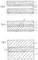
- 1a and 1b show two sheets 1 and 2, which are provided on one side with an enamel layer 3.
- This enamel layer 3 can be applied, for example, by a dipping process or by spraying onto the sheets 1 and 2.
- Fig. 1b shows the sheets 1 and 2 in the interconnected state, in which the joining surfaces 4 between the sheets 1 and 2 are provided with a continuous and homogeneous enamel layer 3.
- 2 shows the mode of operation of the method according to the invention on the basis of an enlarged micrograph according to the dash-dotted circle II in FIG. 1b.
- the heated and viscous enamel layer 3 penetrates into surface roughness 5 of the sheet 2 and thus connects the sheets 1 and 2 after the enamel layer 3 has solidified.
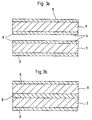
- connection of two sheets 6 and 7 can be seen, which are provided on both sides with an enamel layer 8.
- the connection of the sheets 6 and 7 shown in FIG. 3b comes about in that the mutually facing enamel layers 8 combine in the heated state and in the cooled state bring about a cohesive and gas-tight connection of the sheets 6 and 7.
- the objects consisting of sheets 1 and 2 with a single-sided enamel layer 3 or sheets 6 and 7 with double-sided enamel layer 8 are positioned in the correct position on top of one another and pressed against one another at least on the joining surfaces 4. Then the enamel layer 3 or 8 is heated until it changes to a doughy state.
- the heating can take place, for example, in an oven in which the entire construction is heated, or take place by means of inductive heating, the enamel layer 3 or 8 being heated only indirectly by heating the base material, ie the sheet 1, 2 or 6, 7.
- the base material ie the sheet 1, 2 or 6, 7.
- the sheets 1 and 2 or 6 and 7 are pressure-tight and cohesively connected to one another by a homogeneous enamel layer 3 or 8.
- the plates 1 and 2 or 6 and 7 are connected without the aid of a joining additive or joining agent, since the enamel layer 3 or 8 applied as corrosion protection on the plates 1, 2 or 6, 7 accomplishes the connection of the components.
Abstract
Description
Die Erfindung betrifft ein Verfahren zum druckdichten Verbinden dünnwandiger Gegenstände aus Metall, insbesondere plattenförmiger Bleche, wie Wärmetauscherplatten, die zumindest auf einer Seite als Korrosionsschutz mit einer Emailleschicht versehen sind.The invention relates to a method for the pressure-tight connection of thin-walled objects made of metal, in particular plate-shaped sheets, such as heat exchanger plates, which are provided with an enamel layer on at least one side as corrosion protection.
Aus der Praxis ist es seit langem bekannt, metallische Gegenstände aus Gründen des Oberflächenschutzes mit einer Emailleschicht zu versehen, da dieser glasartig erstarrende silikatische Überzug eine porenfreie und harte Oberfläche ausbildet, durch die der beschichtete Grundwerkstoff geschützt wird. Emaillierte Metallteile weisen jedoch den Nachteil auf, daß sie nicht mittels konventioneller Schweißtechniken miteinander verbunden werden können, da die unterschiedlichen chemischen und physikalischen Eigenschaften des Grundwerkstoffes und der Emaillebeschichtung ein Verschweißen emaillierter Metallteile verhindert. Aus diesem Grund werden Metallkonstruktionen häufig erst verschweißt und anschließend emailliert. Dies hat jedoch den Nachteil, daß schwer zugängliche Bereiche der Konstruktion - wenn überhaupt - nur sehr schwierig mit einer Emailleschicht versehen werden können.It has long been known in practice to provide metallic objects with an enamel layer for reasons of surface protection, since this glass-like, solidifying silicate coating forms a pore-free and hard surface by which the coated base material is protected. Enamelled metal parts have the disadvantage, however, that they cannot be connected to one another by means of conventional welding techniques, since the different chemical and physical properties of the base material and the enamel coating prevent enamelled metal parts from being welded together. For this reason, metal structures are often first welded and then enamelled. However, this has the disadvantage that areas of the construction which are difficult to access - if at all - can be provided with an enamel layer only with great difficulty.
Aus der EP-OS 0 449 377 ist ein Verfahren zum Schweißen emaillierter Metallteile bekannt. Bei diesem bekannten Schweißverfahren werden die zu verschweißenden Metallteile an der Schweißstelle mittels einer Schweißquelle, wie beispielsweise einem Laser, erhitzt und miteinander verschweißt. Durch die gezielte Wärmeeinleitung bei der Verwendung eines Lasers soll bei diesem Verfahren die der Schweißstelle gegenüberliegende Emailleschicht nicht aufgeschmolzen werden, während die Grundstoffe der zu verbindenden Metallteile sich durch Aufschmelzen miteinander verbinden. Dieses Verfahren würde zwar das Verschweißen emaillierter Metallteile ermöglichen, jedoch müßte bei beidseitig emaillierten Metallteilen die Schweißstelle nachträglich mit einer neuen Emailleschicht versehen werden. Bei einseitig emaillierten Metallteilen kann die Verschweißung zwar von der nicht emaillierten Seite aus erfolgen, jedoch ist bei komplizierten und großen Bauteilen der Zugang zu dieser Seite nicht immer gewährleistet, so daß eine druckdichte und stoffschlüssige Verbindung der zu verbindenden Bauteile nicht gewährleistet werden kann.A method for welding enamelled metal parts is known from EP-OS 0 449 377. In this known welding process, the metal parts to be welded are welded at the welding point by means of a welding source, such as, for example a laser, heated and welded together. Due to the targeted introduction of heat when using a laser, the enamel layer opposite the welding point is not to be melted in this method, while the base materials of the metal parts to be joined are joined together by melting. Although this method would enable the welding of enamelled metal parts, the welding point would have to be provided with a new enamel layer in the case of metal parts enamelled on both sides. In the case of metal parts enamelled on one side, the welding can be carried out from the non-enamelled side, but access to this side is not always guaranteed in the case of complicated and large components, so that a pressure-tight and integral connection of the components to be connected cannot be guaranteed.
Der Erfindung liegt die Aufgabe zugrunde, ein Verfahren zum druckdichten Verbinden dünnwandiger, zumindest auf einer Seite mit einer Emailleschicht versehener Gegenstände aus Metall zu schaffen, bei dem die zu verbindenden Gegenstände ohne Zuhilfenahme eines Zusatzwerkstoffes miteinander verbunden werden können und darüber hinaus die Verbindungsstelle nicht nachträglich mit einer Schutzschicht versehen werden muß.The invention has for its object to provide a method for the pressure-tight connection of thin-walled objects made of metal provided at least on one side with an enamel layer, in which the objects to be connected can be connected to one another without the aid of an additional material and, moreover, the connection point is not subsequently added must be provided with a protective layer.
Die Lösung dieser Aufgabenstellung durch die Erfindung ist dadurch gekennzeichnet, daß die miteinander zu verbindenden Gegenstände lagerichtig positioniert und zumindest an den Fügeflächen aneinandergepreßt und derart erwärmt werden, daß die zwischen den Fügeflächen befindliche Emailleschicht in einen teigigen Zustand übergeht und eine stoffschlüssige Verbindung der Gegenstände bewirkt.The solution to this problem by the invention is characterized in that the objects to be connected to one another are positioned in the correct position and are pressed together at least on the joining surfaces and heated in such a way that the enamel layer located between the joining surfaces changes into a doughy state and causes a material connection of the objects.
Durch diese Verfahrensweise ist es möglich, ohne Fügezusätze und Fügemittel eine druckdichte Verbindung der dünnwandigen Gegenstände miteinander zu bewirken. Um ein Ablösen der Emailleschicht von dem Grundwerkstoff zu verhindern, wird die Emailleschicht nicht bis zum Schmelzpunkt bzw. Schmelzbereich erwärmt, sondern nur in einen teigigen Zustand gebracht, der es ermöglicht, daß sich aneinander anliegende Emailleschichten miteinander verbinden bzw. eine emaillierte Schicht und eine nicht emaillierte Schicht dadurch verbinden, daß die Emaille infolge der Wärme und des aufgebrachten Druckes in die Oberflächenrauhigkeiten des anderen Werkstückes eindringt und sich nach dem Erkalten mit diesem verbindet.This procedure enables a pressure-tight connection of the thin-walled objects to one another without joining additives and joining means. In order to prevent the enamel layer from detaching from the base material, the enamel layer is not heated to the melting point or melting range, but is only brought into a pasty state, which makes it possible for adjacent enamel layers to bond with one another or one enamel layer and one not Connect the enamelled layer so that the enamel penetrates into the surface roughness of the other workpiece as a result of the heat and the applied pressure and bonds to it after cooling.
Bei einer bevorzugten Ausführungsform erfolgt die Aufbringung der Wärme und des Druckes unter Normalatmosphäre in einem Ofen. Die Verwendung eines Kammerofens oder eines Durchlaufofens hat den Vorteil, daß komplette Konstruktionen, wie beispielsweise aus vielen Einzelblechen bestehende Wärmetauschermodule, in einem einzigen Ofenzyklus miteinander verbunden werden können. Da die Verbindung der Gegenstände unter Normalatmosphäre stattfinden kann, ist der einzige zu überwachende und zu steuernde Prozeßparameter die Aufheiz- bzw. Abkühlgeschwindigkeit des Ofens.In a preferred embodiment, the heat and the pressure are applied in a furnace under a normal atmosphere. The use of a chamber furnace or a continuous furnace has the advantage that complete structures, such as heat exchanger modules consisting of many individual sheets, can be connected to one another in a single furnace cycle. Since the connection of the objects can take place under a normal atmosphere, the only process parameter to be monitored and controlled is the heating or cooling speed of the furnace.
Bei einer alternativen Ausführungsform des erfindungsgemäßen Verfahrens wird die zur Verbindung benötigte Wärme durch induktive Erwärmung des metallischen Grundwerkstoffes der emaillierten, dünnwandigen Gegenstände erzeugt. Durch diese induktive Erwärmung des Grundwerkstoffes wird die Emailleschicht nur mittelbar, nämlich durch den Grundwerkstoff, erwärmt. Die Verbindung der Gegenstände untereinander erfolgt wiederum durch die in den teigigen Zustand gebrachte Emailleschicht, welche sich aufgrund ihres zähflüssigen Zustandes und des aufgebrachten Druckes mit dem anderen Bauteil verbindet. Bei einer bevorzugten Weiterbildung der Erfindung erfolgt die induktive Erwärmung ausschließlich im Bereich der Fügeflächen, um die Emailleschicht nur in diesem Bereich in den teigigen Zustand zu überführen.In an alternative embodiment of the method according to the invention, the heat required for the connection is generated by inductive heating of the metallic base material of the enamelled, thin-walled objects. This inductive heating of the base material heats the enamel layer only indirectly, namely through the base material. The objects are connected to each other again by the enamel layer brought into the doughy state, which is due to connects their viscous state and the applied pressure with the other component. In a preferred development of the invention, inductive heating takes place exclusively in the area of the joining surfaces in order to convert the enamel layer into the doughy state only in this area.
Der aufzubringende Druck ist notwendig, um eine gute Auflage der zu verbindenden Flächen aufeinander zu gewährleisten. Bei schweren Bauteilen kann dieser Druck alleine schon durch das Eigengewicht der zu verbindenden Gegenstände aufgebracht werden.The pressure to be applied is necessary in order to ensure that the surfaces to be connected rest well on one another. In the case of heavy components, this pressure can be applied simply by the weight of the objects to be connected.
Weitere Einzelheiten und Vorteile ergeben sich aus der nachfolgenden Beschreibung der zugehörigen Zeichnungen, in denen die Arbeitsweise des erfindungsgemäßen Verfahrens schematisch dargestellt ist. In den Zeichnungen zeigen:
- Fig. 1a
- einen Längsschnitt durch zwei zu verbindende, einseitig emaillierte Bleche;
- Fig. 1b
- einen Längsschnitt durch die miteinander verbundenen Bleche gemäß Fig. 1a;
- Fig. 2
- einen Längsschnitt durch die Verbindungsstelle der Bleche gemäß Kreis II in Fig. 1b anhand eines vergrößerten Schliffbildes;
- Fig. 3a
- einen Längsschnitt durch zwei zu verbindende, beidseitig emaillierte Bleche und
- Fig. 3b
- einen Längsschnitt durch die miteinander verbundenen Bleche gemäß Fig. 3a.
- Fig. 1a
- a longitudinal section through two sheets to be joined, enamelled on one side;
- Fig. 1b
- a longitudinal section through the interconnected sheets according to FIG. 1a;
- Fig. 2
- a longitudinal section through the connection point of the sheets according to circle II in Figure 1b based on an enlarged micrograph;
- Fig. 3a
- a longitudinal section through two sheets to be joined, enamelled on both sides and
- Fig. 3b
- a longitudinal section through the interconnected sheets according to FIG. 3a.
Fig. 1a und 1b zeigen zwei Bleche 1 und 2, welche einseitig mit einer Emailleschicht 3 versehen sind. Diese Emailleschicht 3 kann beispielsweise durch ein Tauchverfahren oder durch Aufspritzen auf die Bleche 1 und 2 aufgebracht werden.1a and 1b show two
Fig. 1b zeigt die Bleche 1 und 2 im miteinander verbundenen Zustand, bei dem die Fügeflächen 4 zwischen den Blechen 1 und 2 mit einer durchgehenden und homogenen Emailleschicht 3 versehen sind. Fig. 2 zeigt anhand eines vergrößerten Schliffbildes gemäß dem strichpunktierten Kreis II in Fig. 1b die Wirkungsweise des erfindungsgemäßen Verfahrens. Die erwärmte und zähflüssige Emailleschicht 3 dringt in Oberflächenrauhigkeiten 5 des Bleches 2 ein und verbindet die Bleche 1 und 2 somit nach dem Erstarren der Emailleschicht 3.Fig. 1b shows the
Fig. 3a und 3b ist die Verbindung zweier Bleche 6 und 7 zu entnehmen, die beidseitig mit einer Emailleschicht 8 versehen sind. Hierbei kommt die in Fig. 3b dargestellte Verbindung der Bleche 6 und 7 dadurch zustande, daß sich die einander zugewandten Emailleschichten 8 im erwärmten Zustand vereinigen und im erkalteten Zustand eine stoffschlüssige und gasdichte Verbindung der Bleche 6 und 7 bewirken.3a and 3b, the connection of two
Das erfindungsgemäße Verfahren zum druckdichten Verbinden dünnwandiger, zumindest auf einer Seite mit einer Emailleschicht 3, 8 versehenen Gegenstände arbeitet folgendermaßen:The method according to the invention for the pressure-tight connection of thin-walled objects provided with an
Die aus Blechen 1 und 2 mit einer einseitigen Emailleschicht 3 bzw. Blechen 6 und 7 mit beidseitiger Emailleschicht 8 bestehenden Gegenstände werden lagerichtig aufeinander positioniert und zumindest an den Fügeflächen 4 aneinandergepreßt. Anschließend wird die Emailleschicht 3 bzw. 8 soweit erwärmt, bis diese in einen teigigen Zustand übergeht. Die Erwärmung kann beispielsweise in einem Ofen erfolgen, in dem die gesamte Konstruktion erwärmt wird, oder aber mittels induktiver Erwärmung erfolgen, wobei die Emailleschicht 3 bzw. 8 nur mittelbar durch die Erwärmung des Grundwerkstoffes, d. h. des Bleches 1, 2 bzw. 6, 7 erwärmt wird. Infolge der teigig gewordenen und somit zähflüssigen Emailleschicht 3 bzw. 8 und aufgrund des Anpreßdruckes verbinden sich die aneinander anliegenden Emailleschichten 3 bzw. 8 sowie die Emailleschicht 3 und die nicht emaillierte Fläche. Nach dem Erkalten sind die Bleche 1 und 2 bzw. 6 und 7 durch eine homogene Emailleschicht 3 bzw. 8 druckdicht und stoffschlüssig miteinander verbunden. Die Verbindung der Bleche 1 und 2 bzw. 6 und 7 erfolgt dabei ohne Zuhilfenahme eines Fügezusatzes oder Fügemittels, da die als Korrosionsschutz auf den Blechen 1, 2 bzw. 6, 7 aufgebrachte Emailleschicht 3 bzw. 8 die Verbindung der Bauteile bewerkstelligt.The objects consisting of
- 11
- Blechsheet
- 22nd
- Blechsheet
- 33rd
- EmailleschichtEnamel layer
- 44th
- FügeflächeJoining surface
- 55
- OberflächenrauhigkeitSurface roughness
- 66
- Blechsheet
- 77
- Blechsheet
- 88th
- EmailleschichtEnamel layer
Claims (4)
- Process for the pressure-tight connection of thin-walled objects made of metal, in particular plate-shaped metal sheets, such as heat-exchanger plates, which are provided at least on one side with a layer of enamel as an anti-corrosion measure, characterized in that the objects which are to be connected to one another are placed in the correct position and are pressed against each other at least at the joint surfaces (4) and heated such that the layer of enamel (3, 8) situated between the joint surfaces (4) changes into a pasty state and brings about a material-to-material connection of the objects.
- Method according to Claim 1, characterized in that the application of heat and pressure takes place in a furnace under standard atmosphere.
- Method according to Claim 1, characterized in that the heat is generated by inductive heating of the metallic base material.
- Method according to Claim 3, characterized in that the inductive heating takes place exclusively in the region of the joint surfaces (4).
Applications Claiming Priority (2)
| Application Number | Priority Date | Filing Date | Title |
|---|---|---|---|
| DE4304211 | 1993-02-12 | ||
| DE4304211A DE4304211A1 (en) | 1993-02-12 | 1993-02-12 | Process for the pressure-tight connection of thin-walled objects made of metal |
Publications (3)
| Publication Number | Publication Date |
|---|---|
| EP0610685A2 EP0610685A2 (en) | 1994-08-17 |
| EP0610685A3 EP0610685A3 (en) | 1994-10-12 |
| EP0610685B1 true EP0610685B1 (en) | 1996-10-16 |
Family
ID=6480296
Family Applications (1)
| Application Number | Title | Priority Date | Filing Date |
|---|---|---|---|
| EP94100622A Expired - Lifetime EP0610685B1 (en) | 1993-02-12 | 1994-01-18 | Procedure for making a pressure sealed connection of thin-walled articles made of metal |
Country Status (5)
| Country | Link |
|---|---|
| EP (1) | EP0610685B1 (en) |
| AT (1) | ATE144171T1 (en) |
| DE (2) | DE4304211A1 (en) |
| DK (1) | DK0610685T3 (en) |
| ES (1) | ES2093457T3 (en) |
Families Citing this family (1)
| Publication number | Priority date | Publication date | Assignee | Title |
|---|---|---|---|---|
| EP2436473A1 (en) * | 2010-09-29 | 2012-04-04 | Kompetenzzentrum Neue Materialien Nordbayern GmbH | Method and device for producing a metal body from metal layers arranged over each other |
Family Cites Families (5)
| Publication number | Priority date | Publication date | Assignee | Title |
|---|---|---|---|---|
| US2348696A (en) * | 1941-09-19 | 1944-05-09 | Erie Enameling Company | Method of forming tanks |
| DE2626180A1 (en) * | 1976-06-11 | 1977-12-22 | Baumann Werner Dr Ing | Leak proof joint for enamelled or ceramic pipes - has surface enamel on coupling sleeve heated until plastic to mould to pipes |
| DE2800121A1 (en) * | 1978-01-03 | 1979-07-12 | Maschf Augsburg Nuernberg Ag | Metal plate joining system - using enamel coatings fused to joint by firing |
| NL9000710A (en) * | 1990-03-26 | 1991-10-16 | Ferro Tech | METHOD FOR WELDING ENAMELLED METAL OBJECTS, AND PRODUCT OBTAINED. |
| NL9002406A (en) * | 1990-06-27 | 1992-01-16 | Ferro Tech | METHOD FOR CONNECTING ENAMELLED OBJECTS AND THE OBTAINED COMPOSITION |
-
1993
- 1993-02-12 DE DE4304211A patent/DE4304211A1/en not_active Ceased
-
1994
- 1994-01-18 AT AT94100622T patent/ATE144171T1/en not_active IP Right Cessation
- 1994-01-18 ES ES94100622T patent/ES2093457T3/en not_active Expired - Lifetime
- 1994-01-18 EP EP94100622A patent/EP0610685B1/en not_active Expired - Lifetime
- 1994-01-18 DK DK94100622.3T patent/DK0610685T3/en active
- 1994-01-18 DE DE59400839T patent/DE59400839D1/en not_active Expired - Fee Related
Also Published As
| Publication number | Publication date |
|---|---|
| ATE144171T1 (en) | 1996-11-15 |
| ES2093457T3 (en) | 1996-12-16 |
| EP0610685A2 (en) | 1994-08-17 |
| DE59400839D1 (en) | 1996-11-21 |
| EP0610685A3 (en) | 1994-10-12 |
| DK0610685T3 (en) | 1997-03-24 |
| DE4304211A1 (en) | 1994-08-18 |
Similar Documents
| Publication | Publication Date | Title |
|---|---|---|
| EP2739427B1 (en) | Joining of sheet material having an intermediate sandwich layer of thermoplastic | |
| EP3046813B1 (en) | Joining method | |
| DE102016123555A1 (en) | WELDING ELECTRODE FOR USE IN RESISTANCE SPOT WELDING OF WORKPIECE STACKS CONTAINING AN ALUMINUM WORKPIECE AND A STEEL WORKPIECE | |
| DE19919783B4 (en) | Manufacturing method for a formed by deep drawing, at least two-layer composite sheet metal part | |
| EP1475424B1 (en) | Stackable module | |
| DE3614475A1 (en) | METHOD FOR PRODUCING A COMPOSITE COMPONENT | |
| EP3771878B1 (en) | Method of producing a plate heat exchanger | |
| DE102005038493B4 (en) | Method for producing a joint connection between two sheets | |
| EP1658148B2 (en) | Method for shaping metal sheets | |
| DE102010047033B3 (en) | Molded component useful for a motor vehicle, comprises a base body, which is made of a metal sheet and is provided with a smaller, locally arranged reinforcement plate | |
| DE102018001460A1 (en) | Method and device for integrally joining metallic materials by means of at least one laser beam source | |
| EP0610685B1 (en) | Procedure for making a pressure sealed connection of thin-walled articles made of metal | |
| AT391105B (en) | PRE-MATERIAL FOR THE PRODUCTION OF COMPOSITES | |
| DE102016212622B4 (en) | Process for joining components | |
| EP1585612A1 (en) | Method for joining two metal sheets respectively consisting of an aluminium material and an iron or titanium material by means of a braze welding joint | |
| DE10261073A1 (en) | Process for joining workpieces made of titanium aluminide using a soldering process | |
| EP0767749B1 (en) | Composite car body part and process for manufacturing the same | |
| DE2805233A1 (en) | Bonding steels of different compsns. by heat and pressure - using flame spray applied nickel brazing alloy contg. chromium, boron and silicon | |
| AT413503B (en) | Joining two metal sheets comprises using a blunt joint with a filler material being applied to both sides of the sheets in a region bridging the joint on the metal sheet made from iron or titanium material | |
| EP1582283A1 (en) | Spot welding process of two sheets made in high tensile steel with small plates placed between the sheets | |
| DE102020106476A1 (en) | WELDING DIFFERENT MATERIALS WITH FEATURES IN THE FACILITY | |
| WO1999037523A1 (en) | Method for joining vehicle parts and vehicle parts joined according to said method | |
| DE19835559A1 (en) | Partially strengthened shaped sheet metal components for motor vehicle bodies involves application of a layer of metal powder covering required areas followed by sintering of this layer onto the component | |
| DE102014013211A1 (en) | Method for producing a seam connection between an inner part and an outer part | |
| DE102017107318A1 (en) | PROCESS FOR RESISTANCE SPOT WELDING OF ALUMINUM TO STEEL |
Legal Events
| Date | Code | Title | Description |
|---|---|---|---|
| PUAI | Public reference made under article 153(3) epc to a published international application that has entered the european phase |
Free format text: ORIGINAL CODE: 0009012 |
|
| AK | Designated contracting states |
Kind code of ref document: A2 Designated state(s): AT BE CH DE DK ES FR GB IT LI NL SE |
|
| PUAL | Search report despatched |
Free format text: ORIGINAL CODE: 0009013 |
|
| RAP1 | Party data changed (applicant data changed or rights of an application transferred) |
Owner name: BDAG BALCKE-DUERR AKTIENGESELLSCHAFT |
|
| AK | Designated contracting states |
Kind code of ref document: A3 Designated state(s): AT BE CH DE DK ES FR GB IT LI NL SE |
|
| 17P | Request for examination filed |
Effective date: 19941021 |
|
| GRAG | Despatch of communication of intention to grant |
Free format text: ORIGINAL CODE: EPIDOS AGRA |
|
| GRAH | Despatch of communication of intention to grant a patent |
Free format text: ORIGINAL CODE: EPIDOS IGRA |
|
| 17Q | First examination report despatched |
Effective date: 19960403 |
|
| GRAH | Despatch of communication of intention to grant a patent |
Free format text: ORIGINAL CODE: EPIDOS IGRA |
|
| GRAA | (expected) grant |
Free format text: ORIGINAL CODE: 0009210 |
|
| AK | Designated contracting states |
Kind code of ref document: B1 Designated state(s): AT BE CH DE DK ES FR GB IT LI NL SE |
|
| REF | Corresponds to: |
Ref document number: 144171 Country of ref document: AT Date of ref document: 19961115 Kind code of ref document: T |
|
| ET | Fr: translation filed | ||
| REG | Reference to a national code |
Ref country code: CH Ref legal event code: NV Representative=s name: E. BLUM & CO. PATENTANWAELTE |
|
| GBT | Gb: translation of ep patent filed (gb section 77(6)(a)/1977) |
Effective date: 19961017 |
|
| REF | Corresponds to: |
Ref document number: 59400839 Country of ref document: DE Date of ref document: 19961121 |
|
| REG | Reference to a national code |
Ref country code: ES Ref legal event code: FG2A Ref document number: 2093457 Country of ref document: ES Kind code of ref document: T3 |
|
| ITF | It: translation for a ep patent filed |
Owner name: ING. ZINI MARANESI & C. S.R.L. |
|
| PG25 | Lapsed in a contracting state [announced via postgrant information from national office to epo] |
Ref country code: DK Effective date: 19970118 Ref country code: AT Free format text: LAPSE BECAUSE OF NON-PAYMENT OF DUE FEES Effective date: 19970118 |
|
| REG | Reference to a national code |
Ref country code: DK Ref legal event code: EBP |
|
| PG25 | Lapsed in a contracting state [announced via postgrant information from national office to epo] |
Ref country code: SE Effective date: 19970119 |
|
| PG25 | Lapsed in a contracting state [announced via postgrant information from national office to epo] |
Ref country code: ES Free format text: LAPSE BECAUSE OF NON-PAYMENT OF DUE FEES Effective date: 19970120 |
|
| PG25 | Lapsed in a contracting state [announced via postgrant information from national office to epo] |
Ref country code: LI Effective date: 19970131 Ref country code: CH Effective date: 19970131 Ref country code: BE Effective date: 19970131 |
|
| REG | Reference to a national code |
Ref country code: DK Ref legal event code: T3 |
|
| BERE | Be: lapsed |
Owner name: BALCKE-DURR A.G. BDAG Effective date: 19970131 |
|
| PLBE | No opposition filed within time limit |
Free format text: ORIGINAL CODE: 0009261 |
|
| STAA | Information on the status of an ep patent application or granted ep patent |
Free format text: STATUS: NO OPPOSITION FILED WITHIN TIME LIMIT |
|
| REG | Reference to a national code |
Ref country code: CH Ref legal event code: PL |
|
| PG25 | Lapsed in a contracting state [announced via postgrant information from national office to epo] |
Ref country code: FR Effective date: 19970930 |
|
| PG25 | Lapsed in a contracting state [announced via postgrant information from national office to epo] |
Ref country code: DE Effective date: 19971001 |
|
| EUG | Se: european patent has lapsed |
Ref document number: 94100622.3 |
|
| 26N | No opposition filed | ||
| REG | Reference to a national code |
Ref country code: FR Ref legal event code: ST |
|
| PG25 | Lapsed in a contracting state [announced via postgrant information from national office to epo] |
Ref country code: GB Free format text: LAPSE BECAUSE OF NON-PAYMENT OF DUE FEES Effective date: 19980118 |
|
| PG25 | Lapsed in a contracting state [announced via postgrant information from national office to epo] |
Ref country code: NL Free format text: LAPSE BECAUSE OF NON-PAYMENT OF DUE FEES Effective date: 19980801 |
|
| GBPC | Gb: european patent ceased through non-payment of renewal fee |
Effective date: 19980118 |
|
| NLV4 | Nl: lapsed or anulled due to non-payment of the annual fee |
Effective date: 19980801 |
|
| REG | Reference to a national code |
Ref country code: ES Ref legal event code: FD2A Effective date: 20021016 |
|
| PG25 | Lapsed in a contracting state [announced via postgrant information from national office to epo] |
Ref country code: IT Free format text: LAPSE BECAUSE OF NON-PAYMENT OF DUE FEES;WARNING: LAPSES OF ITALIAN PATENTS WITH EFFECTIVE DATE BEFORE 2007 MAY HAVE OCCURRED AT ANY TIME BEFORE 2007. THE CORRECT EFFECTIVE DATE MAY BE DIFFERENT FROM THE ONE RECORDED. Effective date: 20050118 |