EP0610666A1 - Turbomolecular pump - Google Patents
Turbomolecular pump Download PDFInfo
- Publication number
- EP0610666A1 EP0610666A1 EP94100312A EP94100312A EP0610666A1 EP 0610666 A1 EP0610666 A1 EP 0610666A1 EP 94100312 A EP94100312 A EP 94100312A EP 94100312 A EP94100312 A EP 94100312A EP 0610666 A1 EP0610666 A1 EP 0610666A1
- Authority
- EP
- European Patent Office
- Prior art keywords
- pump
- panel
- vacuum chamber
- vacuum
- pump casing
- Prior art date
- Legal status (The legal status is an assumption and is not a legal conclusion. Google has not performed a legal analysis and makes no representation as to the accuracy of the status listed.)
- Granted
Links
Images


Classifications
-
- F—MECHANICAL ENGINEERING; LIGHTING; HEATING; WEAPONS; BLASTING
- F04—POSITIVE - DISPLACEMENT MACHINES FOR LIQUIDS; PUMPS FOR LIQUIDS OR ELASTIC FLUIDS
- F04B—POSITIVE-DISPLACEMENT MACHINES FOR LIQUIDS; PUMPS
- F04B37/00—Pumps having pertinent characteristics not provided for in, or of interest apart from, groups F04B25/00 - F04B35/00
- F04B37/06—Pumps having pertinent characteristics not provided for in, or of interest apart from, groups F04B25/00 - F04B35/00 for evacuating by thermal means
-
- F—MECHANICAL ENGINEERING; LIGHTING; HEATING; WEAPONS; BLASTING
- F04—POSITIVE - DISPLACEMENT MACHINES FOR LIQUIDS; PUMPS FOR LIQUIDS OR ELASTIC FLUIDS
- F04D—NON-POSITIVE-DISPLACEMENT PUMPS
- F04D19/00—Axial-flow pumps
- F04D19/02—Multi-stage pumps
- F04D19/04—Multi-stage pumps specially adapted to the production of a high vacuum, e.g. molecular pumps
- F04D19/046—Combinations of two or more different types of pumps
-
- F—MECHANICAL ENGINEERING; LIGHTING; HEATING; WEAPONS; BLASTING
- F04—POSITIVE - DISPLACEMENT MACHINES FOR LIQUIDS; PUMPS FOR LIQUIDS OR ELASTIC FLUIDS
- F04D—NON-POSITIVE-DISPLACEMENT PUMPS
- F04D29/00—Details, component parts, or accessories
- F04D29/58—Cooling; Heating; Diminishing heat transfer
- F04D29/582—Cooling; Heating; Diminishing heat transfer specially adapted for elastic fluid pumps
- F04D29/584—Cooling; Heating; Diminishing heat transfer specially adapted for elastic fluid pumps cooling or heating the machine
Definitions
- the invention relates to vacuum apparatus and, more particularly, to turbomolecular pumps used for producing a vacuum in vacuum chambers.
- Vacuum processes are used widely in semiconductor, optics, and other fields of industry.
- a vacuum process is used in the physical vapor deposition (PVD) method of fabricating thin film conductors.
- PVD physical vapor deposition
- Such thin films are principally fabricated through physical deposition of metals upon various substrate materials.
- PVD technique used in fabricating metallic thin films is a sputtering method.
- the sputtering method involves accelerating, by means of electrical discharges, argon (Ar+) and other ionic elements in a vacuum. The accelerated ions collide with a negative potential electrode (target).
- the material comprising the electrode escapes from the surface thereof by receiving the energy of the argon (Ar+) ions (in a phenomenon called "sputtering"), and the substance escaping the electrode deposits itself on a substrate. The result is the formation of a metallic thin film on the substrate.
- cryogenic pump cryo-pump
- turbomolecular pump turbomolecular pump
- cryo-pump 112 is attached by a duct 108 to a vacuum chamber 106 through a main valve (high-vacuum valve) 110.
- the cryo-pump 112 is connected to a rotary pump (a mechanical pump) 118 through a cryogenic rough valve 114.
- the rotary pump is used to initially create a partial vacuum (also known as a low or rough vacuum) in the chamber and the cryo-pump is used after the partial vacuum is created to further evacuate the chamber.
- a rough evacuation duct 120 connects the vacuum chamber 106 to a duct 116 that links the cryogenic valve 114 to the rotary pump 118.
- a chamber rough valve 122 located in duct 120, controls flow therethrough.
- Another duct 104 protrudes from the vacuum chamber 106, and a chamber vent valve 102 is provided at a point along this duct.
- the cryo-pump system To produce a vacuum in vacuum chamber 106, the cryo-pump system must perform the following steps: (1) the chamber vent valve 102, main valve 110, and cryogenic rough valve 114 are closed; (2) the chamber rough valve 122 is opened; (3) the rotary pump 118 is then activated in order to perform a rough evacuation of the vacuum chamber 106; (4) the chamber rough valve 122 is closed; (5) main valve 110 is opened; and (6) the cryo-pump 112 is activated in order to perform a secondary evacuation of the vacuum chamber 106. The secondary evacuation produces a sufficient vacuum in the vacuum chamber that facilitates use of a sputtering process therein.
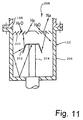
- FIG.11 depicts a conventional cryo-pump 112 as used in the cryo-pump system described above.
- Cryo-pump 112 contains a rotational axis 204 that is connected at one end to a small helium-gas refrigerator (not shown). Another end of the rotational axis 204 enters into a pump case 206. At the tip of the axis is a cold vane 202.
- a baffle 200 is provided at the inlet of the pump case 206.
- the duct 108 is connected to the periphery of an inlet 208.
- the baffle 200, the cold vane 202, and other components are maintained at a cryogenic temperature, i.e., a temperature at which molecules are adsorbed by the baffle, cold vane and other cold components of the cryo-pump.
- a cryogenic temperature i.e., a temperature at which molecules are adsorbed by the baffle, cold vane and other cold components of the cryo-pump.
- gas molecules that enter inlet 208 through the duct 108 water vapor and any other elements and molecules that have a vapor pressure higher than that of water are condensed upon the baffle 200. As such, these molecules and elements are eliminated from the vacuum chamber.
- a cryo-pump requires a relatively long startup time, i.e., until the pump is cooled to a prescribed cryogenic temperature, and a relatively long shutdown time, i.e., until the temperature of the pump rises to a prescribed temperature.
- startup and shutdown times are each on the order of one to two hours.
- the vacuum chamber must remain sealed and connected to the cryo-pump.
- the main valve is provided between the cryo-pump and the vacuum chamber.
- the main valve is closed and the vacuum chamber can be brought to atmospheric pressure.
- workers can have access to the chamber without waiting for the cryo-pump to warm, i.e., without waiting the shutdown period.
- the cryo-pump can be warmed in isolation from the vacuum chamber such that the water vapor and other contaminants previously captured by the pump do not evaporate from the cryo-pump and enter the vacuum chamber.
- the main valve is a high-vacuum bellows valve or other similar-type high vacuum valve.
- the large pressure difference between the high-vacuum side and the atmospheric side, and the need for airtight sealing make the structure of the main valve necessarily complex. Consequently, the structural complexity of the main valve, increases the surface areas of the valve components. Because the valve operates in a high vacuum, the dust accumulated on the surfaces of these components creates, within the vacuum chamber, a potential particle contamination problem. Also, gases emanate from the constituent materials of the valve components, i.e., outgassing. These gases flow into the vacuum chamber and detract from the creation of a high vacuum.
- an ideal solution from the standpoint of ensuring a high vacuum in the vacuum chamber, is elimination of the main valve between the vacuum chamber and the cryo-pump.
- turbomolecular pumps turbomolecular pumps
- FIG. 12 An illustrative vacuum system that uses a turbo-pump 300 having a cold trap panel 318 is depicted in FIG. 12.
- the cold trap panel which is provided at the inlet 323, is designed to adsorb water molecules much like the baffle in a cryo-pump adsorbs water molecules.
- a shaft 306, to which an impeller 310 is attached, is contained in the pump case 302. The shaft forms a main axis of rotation for the impeller.
- the shaft 306 is supported by top and bottom touchdown bearings 304 and a motor magnet bearing 308 (a portion of electric motor 324).
- a cold panel casing 314 is attached to the periphery of the inlet for the pump case 302.
- the cold trap panel 318 protected by a cover 316, is provided inside the cold panel casing 314.
- a cooling medium pipe 320 linked to a refrigerator (not shown) is attached to the cold trap panel 318.
- a duct 322, which carries the contaminants from the vacuum chamber, is connected to the cold panel casing 314.
- the gaseous molecules entering the pump via the inlet to the pump case undergo compression by the high-speed rotation of the impeller 310 and are discharged through the exhaust vent 312.
- the gaseous molecules entering from the inlet 323 are cooled by the cold trap panel 318 such that only the water molecules, which constitute the predominant proportion of the gas residues remaining in the vacuum chamber to which the turbo-pump is connected, are adsorbed onto the cold trap panel. Therefore, the evacuation span of the water molecules freezing on the trap panel is considerably longer than in the case of a cryo-pump. This permits the selective and continuous evacuation operation of the turbo pump.
- a turbo-pump with a cold trap panel requires vaporization of the water molecules presently adsorbed by the trap.
- vaporization is accomplished by allowing the cold trap panel to warm to room temperature while rotating the impeller such that vaporized water molecules are drawn into the pump and not permitted to enter the vacuum chamber.
- the temperature of the cold trap panel is raised from a cryogenic temperature, e.g., the temperature at which water molecules can be adsorbed, approximately 100 degrees Kelvin, to approximately room temperature, e.g., 300 degrees Kelvin.
- a cryogenic temperature e.g., the temperature at which water molecules can be adsorbed
- turbo-pump vacuum system can be used without a main valve, to enable the vacuum chamber to be entered prior to fully warming the cold trap panel, a main valve is used to isolate the vacuum chamber from the turbo-pump.
- a main valve is used to isolate the vacuum chamber from the turbo-pump.
- turbo-pump depicted in FIG. 12 suffers from the disadvantage that the cold trap panel located at the inlet of the pump case substantially reduces the effective suction area of the inlet, i.e., the cold trap panel partially blocks the inlet. Consequently, the location and shape of the cold trap panel reduces the conductance of the pump, thus decreasing the performance of the turbo-pump.
- the present invention provides a turbomolecular pump having a cold trap panel that does not significantly impact the effective suction area of the turbo-pump. Additionally, a heater is positioned in an inlet to the turbo-pump, near the cold trap panel, such that, when energized, the heater quickly vaporizes any molecules adsorbed by the cold trap panel. Consequently, the shutdown duration is substantially shortened as compared to the prior art and a vacuum system that employs the inventive turbo-pump does not require a main valve to isolate the pump from the vacuum chamber during the shutdown duration.
- the inventive turbo-pump contains a cold trap panel having an annular member, a disk-shaped member and a supporting frame that connects the annular member to the disk-shaped member such that these members are coaxial positioned relative to one another.
- the trap panel is positioned within an inlet to the turbo-pump and coaxially aligned with the main axis of an impeller thereof.
- Such a cold trap panel when positioned in the inlet, has an insignificant impact on the effective suction area of the inlet to the pump.
- a heater is located proximate the trap panel such that, when energized, the heater relatively quickly vaporizes any molecules adsorbed by the trap panel. Since use of such a heater significantly reduces the shutdown duration of the turbo-pump, a vacuum system utilizing the inventive turbo-pump does not require a main valve to isolate the pump from the vacuum chamber. Furthermore, use of the inventive turbo-pump in a vacuum does not require a rotary pump to initially evacuate (rough pump) the vacuum chamber prior to using the turbo-pump. Consequently, such a vacuum system is simpler and its use is more efficient than those found in the art.
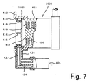
- FIG. 1 shows a partial sectional side view of a turbomolecular pump (turbo-pump) 400 with a cold trap panel (trap panel) 414 in accordance with a first embodiment of the invention.
- FIG. 2 shows a vertical cross-sectional front view of the trap panel and
- FIG. 3 shows a perspective view of the trap panel. To best understand the first embodiment of the invention, the reader should simultaneously view FIGs. 1, 2 and 3.
- an impeller 406, integral with a shaft 404, is provided inside a pump case 402. Connected to one end of the pump case is an exhaust vent 408.
- An inlet 410 to the pump is provided on the other end of the pump case.
- the trap panel 414 is provided at the inlet 410 of the pump case 402.
- the trap panel 414 contains an annular trap panel 416.
- the outer edges of a supporting frame 418 are securely attached to the inner circumference of the annular trap panel 416 such that individual elements of the supporting frame, when viewed from the front, orthogonally intersect at the center of the annular trap panel, forming a cross.
- a central trap panel 420 is centrally attached to one side of the supporting frame 418.
- the inner diameter of the annular trap panel 416 is approximately equal to the outer diameter of the impeller 406.
- the central trap panel 420 has a disc shape, which is approximately the same shape as the cross-section of shaft 404 of the impeller 406, and the diameter of the disc is approximately equal to the diameter of the shaft 404.
- the central trap panel 420 and the shaft 404 are coaxially positioned.
- the annular trap panel 416, the supporting frame 418, and the central trap panel 420 are all cold panels which adsorb water molecules from the gases passing from a vacuum chamber into the pump. These units are designed to reduce the length of evacuation time by rapid elimination of water molecules.
- a thermal conductor 422 made of copper and other materials of high coefficients of thermal conductivity, is connected to the annular trap panel 416 and supports it within the inlet to the pump.
- One end of the thermal conductor 422 is connected to a cooling unit 424 of a refrigerator 426.
- the refrigerator 426 cools the trap panel 414 to a low-temperature (typically, 100 degrees Kelvin).
- the specific low-temperature of the trap panel 414 is determined by the thermal load on the trap panel and the cooling capacity balance thereof created by the specific application of the turbo-molecular pump.
- the refrigerator 426 is attached to an end of a holding case 428, which forms an integral unit with the pump case 402. Both the cooling unit 424 of the refrigerator 426 and the thermal conductor 422 are housed in the holding case 428.
- the rotation of the impeller 406 causes gaseous molecules in a vacuum chamber connected thereto to be drawn through the inlet 410 into the pump case 402 and discharged from the exhaust vent 408.
- gaseous molecules in a vacuum chamber connected thereto to be drawn through the inlet 410 into the pump case 402 and discharged from the exhaust vent 408.
- water molecules which typically represent a predominant proportion of the gaseous molecules in the vacuum chamber, are condensed and frozen by the trap panel 414 at the inlet of the pump case. As such, the water molecules are eliminated from the vacuum chamber.
- the annular trap panel 416 is positioned proximate the periphery of the impeller 406, and the central trap panel 420 is coaxial with the main axis of the impeller.
- Such an arrangement ensures that the trap panel does not decrease the effective suction area of the inlet to the pump case. As such, the performance capacity of the turbo-pump is not compromised by the trap panel being located in the inlet.
- FIG. 4 depicts an illustrative vacuum system 701 using the inventive turbo-pump 400 equipped with a trap panel 414 shown in FIG. 1.
- a vacuum chamber 704 and the turbo-pump 400 equipped with a trap panel are interconnected through a duct 708 that contains a main valve 706.
- the turbo-pump 400 is connected to a rotary pump 712 through an auxiliary valve 710.
- a duct 702 protrudes from the vacuum chamber 704 through the chamber vent valve 700.
- a duct 716, for rough pumping the chamber connects the chamber to the rotary pump 712.
- a chamber rough valve 714 located in duct 716, controls flow through that duct.
- This vacuum system creates a rough vacuum in vacuum chamber 704 using the following steps: (1) closing the chamber vent valve 700; (2) opening the chamber rough valve 714; and (3) activating the rotary pump 712 in order to perform a rough evacuation of the vacuum chamber 704.
- rough valve 714 is closed and the exhaust vent of turbo-pump 400 is connected to the rotary pump by opening the auxiliary valve 710.
- the turbo-pump and the refrigerator for the pump's trap panel are activated.
- the turbo-pump reaches a constant rotational speed in a few minutes.
- the main valve 706 is opened in order to further evacuate the vacuum chamber 704.
- the trap panel 704 attains a constant cryogenic temperature that is sufficiently cold to trap water molecules. The result is a secondary evacuation of the vacuum chamber.
- FIG. 5 denotes the size of an area (effective suction area) through which a vane for the impeller 406 rotates
- b denotes the size of an area (non-effective suction area) of the shaft 404, which does not contain a vane.
- a represents the size of an area of the pump inlet that actually produces suction
- b represents the size of an area of the pump that does not produce suction.
- the trap panel 414 is a contiguous annular ring
- the present invention is not limited to only this configuration.
- sector-shaped panels portions of a non-contiguous ring, each attached to an individual element of the support frame and arranged in ring form, can produce the same cold trap effect without significantly impacting the effective suction area of the pump inlet.
- a trap panel is provided in such a way that the effective suction area of inlet of the turbo-pump is not significantly diminished.
- This configuration maximizes the conductance and eliminates the need for enlarging the gas inlet in order to compensate for the space occupied by the trap panel.
- the result is a cold trap panel that does not significantly impact the performance characteristics of the turbo-pump to which it is connected.
- a heater 1002 consisting of a heating coil, is provided between the trap panel 414 and the inlet 410 of the pump case 402.
- the purpose of the heater 1002 is to rapidly evaporate the water molecules adsorbed on the trap panel 414 through the application of external energy. Therefore, the heater 1002 can be configured and arranged in any way that effectively evaporates the water molecules and should not be construed as being limited to the specific configuration and arrangement shown in FIG. 7.
- the heater may be an electrical heating coil, a coil of tubing carrying a heated liquid, a plurality of infrared heating element, and the like.
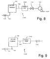
- FIG. 8 shows a turbo-pump 1000 of the second embodiment of the present invention as used in an illustrative vacuum system 1100.
- a duct 708 directly interconnects the vacuum chamber 704 with the turbo-pump 1000, i.e., a main valve is not used.
- the turbo-pump 1000 is connected to a rotary pump 712 through an auxiliary valve 710.
- a duct 702 protrudes from the vacuum chamber 704 through a chamber vent valve 700.
- Evacuation using the vacuum system of FIG. 8 is performed by closing the chamber vent valve 700, opening the auxiliary valve 710, and running the rotary pump 712 in order to perform a rough evacuation inside the vacuum chamber 704. Simultaneously, the turbo-pump 1000 and the refrigerator for the pump's trap panel are activated. The turbo-pump, upon reaching a constant rotational speed, further evacuates the interior of the vacuum chamber 704. Approximately one hour later, the trap panel reaches a constant cryogenic temperature and the vacuum chamber 704 attains a high vacuum.
- the rotation of the impeller vanes cause the gaseous molecules in the vacuum chamber to be drawn, through the inlet, into the pump case and discharged from the exhaust vent. Additionally, during pumping, water molecules, which represent a predominant proportion of the gaseous molecules, are condensed and frozen at the entrance of the pump case by the trap panel. The result is an efficient evacuation of the vacuum chamber.
- the temperature of the trap panel of the turbo-pump must be quickly raised from the cryogenic temperature (approximately 100 degrees Kelvin) to ordinary room temperature (approximately 300 degrees Kelvin).
- the water molecules adsorbed on the trap panel are rapidly gasified or liquefied, and detrimentally flow into the vacuum chamber.
- the provision of the heater in close proximity to the inlet of the turbo-pump permits warming of the trap panel from the cryogenic temperature to room temperature in a relatively short duration of several minutes, e.g., approximately ten (10) minutes.
- the impeller draws the evaporated water molecules into the pump and away from the vacuum chamber.
- the auxiliary valve 710 is closed, the turbo-pump 1000 is simultaneously deactivated, and the chamber vent valve 700 is opened, and then the vacuum chamber 704 is vented in order to bring the pressure inside the vacuum chamber to atmospheric pressure.
- the heater of the present invention uses the heater of the present invention to take about 10 minutes before venting of the vacuum chamber can be commenced.
- this ten minute waiting period is not necessary because the main valve is used to isolate the vacuum chamber from the pump.
- the waiting period is necessary precondition to the elimination of the main valve, and, as discussed above, the elimination of the main valve yields significant advantages.
- FIG. 9 depicts another vacuum system 1200 in which the inventive turbo-pump 1000 shown in FIG. 7 is used.
- a rotary pump is not used to initially evacuate the vacuum chamber 704 prior to using the turbo-pump.
- the exhaust vent of the turbo-pump 1000 is connected through valve 710 to the atmosphere.
- turbo-pump 1000 directly evacuates the vacuum chamber, i.e., without the use of a rough pump to initially evacuate the vacuum chamber.
- the heater and cold trap panel in the turbo-pump 1000 permit the pump to be directly connected to the vacuum chamber by duct 708. Consequently, the vacuum system 1200 is significantly simplified as compared to the prior art.
- the evacuation system of this invention is capable of eliminating gaseous molecules through the use of a turbomolecular pump.
- a trap panel Through the use of a trap panel, it can also eliminate water molecules, which represent a predominant proportion of the gaseous molecules contained in a vacuum chamber.
- the inventive design of the trap panel ensures that the turbo-pump maintains a relatively high conductance though fitted with a trap panel at its inlet. Further, the heater provided at the inlet quickly vaporizes and eliminates the water molecules that condense on the trap panel, thus reducing the length of time that the turbo-pump requires for shutdown. The result is improved operational efficiency of a vacuum system that utilizes the inventive turbo-pump. Further, the reduction in turbo-pump shutdown duration permits the turbo molecular pump to be directly connected to the vacuum chamber. This advantageously permits eliminating the conventional main valve in the vacuum system.
- the invention provides a turbo-pump equipped with a trap panel, in which an impeller integrated with the main axis is housed in the pump case, and in which a trap panel is provided at the inlet of the pump case; the said turbo-pump equipped with a trap panel characterized in that the trap panel is positioned at the center of two ring-shaped trap panels, that the trap panel is composed of a central trap panel supported by the ring-shaped trap panels through the use of a supporting frame, such that the central trap panel and the main axis are positioned on the same axial line.
- the invention further provides the turbo-pump equipped with a trap panel , characterized in that if “a” denotes the size of the effective suction unit between the end of the impeller and the main axis, "b” denotes the diameter of the main axis, “a1” denotes the size measured from the outer circumference of the central trap panel to the inner circumference of the ring-shaped trap panels, and “b1” denotes the diameter of the central trap panel, then the following relationships hold: a1 a, b1 b.
- the invention provides a vacuum evacuation device that evacuates the gas in a vacuum chamber by means of a vacuum pump, wherein said vacuum evacuation device is characterized in that the aforementioned vacuum pump comprises a turbo-pump, equipped with a trap panel that possesses a heating device in the air intake.
- the invention provides the vacuum evacuation device , which is characterized in that it is structured such that the aforementioned turbo-pump equipped with a trap panel is directly connected to the vacuum chamber via a conduit.
- the invention teaches to replace the conventional high-vacuum pump (oil diffusion pump, turbo-pump, cryo-pump) and low-vacuum pump (rotary oil pump, various types of dry pumps) with a turbo-type dry pump, and an H2O trap is added.
- turbo-type dry pump and trap that can be started up or shut down in a few minutes, the main valve becomes unnecessary.
- the high-vacuum pump and low-vacuum pump and main valve combination can be replaced with a trap and turbo-type dry pump, resulting in simpler design, smaller size and lower cost.
- This invention can be utilized in various high-vacuum equipment, such as evaporation systems, vacuum smelting systems, CVD systems, etc.
Abstract
Description
- The invention relates to vacuum apparatus and, more particularly, to turbomolecular pumps used for producing a vacuum in vacuum chambers.
- Vacuum processes are used widely in semiconductor, optics, and other fields of industry. For example, in the electronics industry, a vacuum process is used in the physical vapor deposition (PVD) method of fabricating thin film conductors. Such thin films are principally fabricated through physical deposition of metals upon various substrate materials. One such PVD technique used in fabricating metallic thin films is a sputtering method. In general, the sputtering method involves accelerating, by means of electrical discharges, argon (Ar+) and other ionic elements in a vacuum. The accelerated ions collide with a negative potential electrode (target). The material comprising the electrode escapes from the surface thereof by receiving the energy of the argon (Ar+) ions (in a phenomenon called "sputtering"), and the substance escaping the electrode deposits itself on a substrate. The result is the formation of a metallic thin film on the substrate.
- Such sputtering equipment is typically enclosed in a vacuum chamber. As such, the transformation of the thin-film substance from the electrode into highly energetic ions occurs in a vacuum. Consequently, an evacuation or vacuum apparatus is necessary in order to substantially eliminate any gas from the vacuum chamber within which the sputtering process is accomplished. Conventionally, either a cryogenic pump (cryo-pump) or a turbomolecular pump (turbo-pump) containing a cold trap panel is used for this purpose.
- With reference to FIG. 10, the following is a description of a cryo-
pump system 100 that uses a helium gas refrigerator to cool the pump. In this illustrative cryo-pump system, the cryo-pump 112 is attached by aduct 108 to avacuum chamber 106 through a main valve (high-vacuum valve) 110. The cryo-pump 112 is connected to a rotary pump (a mechanical pump) 118 through a cryogenicrough valve 114. The rotary pump is used to initially create a partial vacuum (also known as a low or rough vacuum) in the chamber and the cryo-pump is used after the partial vacuum is created to further evacuate the chamber. Arough evacuation duct 120 connects thevacuum chamber 106 to aduct 116 that links thecryogenic valve 114 to therotary pump 118. A chamberrough valve 122, located induct 120, controls flow therethrough. Anotherduct 104 protrudes from thevacuum chamber 106, and achamber vent valve 102 is provided at a point along this duct. - Operation of such a cryo-pump system is complex and time consuming. Specifically, to produce a vacuum in
vacuum chamber 106, the cryo-pump system must perform the following steps: (1) thechamber vent valve 102,main valve 110, and cryogenicrough valve 114 are closed; (2) the chamberrough valve 122 is opened; (3) therotary pump 118 is then activated in order to perform a rough evacuation of thevacuum chamber 106; (4) the chamberrough valve 122 is closed; (5)main valve 110 is opened; and (6) the cryo-pump 112 is activated in order to perform a secondary evacuation of thevacuum chamber 106. The secondary evacuation produces a sufficient vacuum in the vacuum chamber that facilitates use of a sputtering process therein. - FIG.11 depicts a conventional cryo-
pump 112 as used in the cryo-pump system described above. Cryo-pump 112 contains arotational axis 204 that is connected at one end to a small helium-gas refrigerator (not shown). Another end of therotational axis 204 enters into apump case 206. At the tip of the axis is acold vane 202. Abaffle 200 is provided at the inlet of thepump case 206. Theduct 108 is connected to the periphery of aninlet 208. - In the cryo-
pump 112, thebaffle 200, thecold vane 202, and other components are maintained at a cryogenic temperature, i.e., a temperature at which molecules are adsorbed by the baffle, cold vane and other cold components of the cryo-pump. Of the gas molecules that enterinlet 208 through theduct 108, water vapor and any other elements and molecules that have a vapor pressure higher than that of water are condensed upon thebaffle 200. As such, these molecules and elements are eliminated from the vacuum chamber. Other gasses, such as nitrogen, oxygen, and argon, whose vapor pressure is lower than the vapor pressure of water, adhere to thecold vane 202. Gases of even lower vapor pressures are adsorbed by a cold panel (not shown), - These gases are then conventionally captured by respective adsorption agents.
- Detrimentally, a cryo-pump requires a relatively long startup time, i.e., until the pump is cooled to a prescribed cryogenic temperature, and a relatively long shutdown time, i.e., until the temperature of the pump rises to a prescribed temperature. Generally, the startup and shutdown times are each on the order of one to two hours. During the shutdown time, to ensure that the adsorbed gasses do not evaporate and enter the vacuum chamber, the vacuum chamber must remain sealed and connected to the cryo-pump. Thus, to enable isolation of the cryo-pump from the vacuum chamber and permit access to the chamber shortly after processing within the chamber is completed, the main valve is provided between the cryo-pump and the vacuum chamber. As such, once the sputtering process is complete, the main valve is closed and the vacuum chamber can be brought to atmospheric pressure. Thus, workers can have access to the chamber without waiting for the cryo-pump to warm, i.e., without waiting the shutdown period. Furthermore, by using a main valve, the cryo-pump can be warmed in isolation from the vacuum chamber such that the water vapor and other contaminants previously captured by the pump do not evaporate from the cryo-pump and enter the vacuum chamber.
- However, use of such a main valve has certain drawbacks. Typically, the main valve is a high-vacuum bellows valve or other similar-type high vacuum valve. As such, the large pressure difference between the high-vacuum side and the atmospheric side, and the need for airtight sealing, make the structure of the main valve necessarily complex. Consequently, the structural complexity of the main valve, increases the surface areas of the valve components. Because the valve operates in a high vacuum, the dust accumulated on the surfaces of these components creates, within the vacuum chamber, a potential particle contamination problem. Also, gases emanate from the constituent materials of the valve components, i.e., outgassing. These gases flow into the vacuum chamber and detract from the creation of a high vacuum. Therefore, an ideal solution, from the standpoint of ensuring a high vacuum in the vacuum chamber, is elimination of the main valve between the vacuum chamber and the cryo-pump. However, it is not possible to eliminate the main valve from the type of vacuum pump system of FIG. 10 without risking contamination of the vacuum chamber during shutdown (warming) of the cryo-pump.
- In an attempt to eliminate the use of a main valve in a vacuum system, those skilled in the art have turned to using turbomolecular pumps (turbo-pumps) rather than cryo-pumps. An illustrative vacuum system that uses a turbo-
pump 300 having acold trap panel 318 is depicted in FIG. 12. The cold trap panel, which is provided at theinlet 323, is designed to adsorb water molecules much like the baffle in a cryo-pump adsorbs water molecules. In this turbo-pump, ashaft 306, to which animpeller 310 is attached, is contained in thepump case 302. The shaft forms a main axis of rotation for the impeller. Theshaft 306 is supported by top andbottom touchdown bearings 304 and a motor magnet bearing 308 (a portion of electric motor 324). At the bottom of thepump case 302 is anexhaust vent 312. Acold panel casing 314 is attached to the periphery of the inlet for thepump case 302. Thecold trap panel 318, protected by acover 316, is provided inside thecold panel casing 314. To reduce the temperature of the cold trap panel, acooling medium pipe 320 linked to a refrigerator (not shown) is attached to thecold trap panel 318. Aduct 322, which carries the contaminants from the vacuum chamber, is connected to thecold panel casing 314. - In the turbo-
pump 300, the gaseous molecules entering the pump via the inlet to the pump case undergo compression by the high-speed rotation of theimpeller 310 and are discharged through theexhaust vent 312. During this process, the gaseous molecules entering from theinlet 323 are cooled by thecold trap panel 318 such that only the water molecules, which constitute the predominant proportion of the gas residues remaining in the vacuum chamber to which the turbo-pump is connected, are adsorbed onto the cold trap panel. Therefore, the evacuation span of the water molecules freezing on the trap panel is considerably longer than in the case of a cryo-pump. This permits the selective and continuous evacuation operation of the turbo pump. - In a turbo-pump system, excessive accumulation of water molecules on the cold trap panel impedes the effectiveness of the panel to further trap water molecules. Therefore, periodically and between uses of the vacuum chamber, a turbo-pump with a cold trap panel requires vaporization of the water molecules presently adsorbed by the trap. Typically, vaporization is accomplished by allowing the cold trap panel to warm to room temperature while rotating the impeller such that vaporized water molecules are drawn into the pump and not permitted to enter the vacuum chamber. Thus, prior to venting the interior of the vacuum chamber to atmospheric pressure, the temperature of the cold trap panel is raised from a cryogenic temperature, e.g., the temperature at which water molecules can be adsorbed, approximately 100 degrees Kelvin, to approximately room temperature, e.g., 300 degrees Kelvin. Such warming (shutdown time) requires about one hour to accomplish.
- Although, such a turbo-pump vacuum system can be used without a main valve, to enable the vacuum chamber to be entered prior to fully warming the cold trap panel, a main valve is used to isolate the vacuum chamber from the turbo-pump. Such a configuration, therefore, is susceptible to problems of dust and gas generation from the main valve, as in the case of a cryo-pump.
- Furthermore, the turbo-pump depicted in FIG. 12 suffers from the disadvantage that the cold trap panel located at the inlet of the pump case substantially reduces the effective suction area of the inlet, i.e., the cold trap panel partially blocks the inlet. Consequently, the location and shape of the cold trap panel reduces the conductance of the pump, thus decreasing the performance of the turbo-pump.
- Therefore, it is an object of the present invention to provide a turbo-pump with a cold trap panel that reduces the shutdown time required to vaporize accumulated water molecules on the cold trap panel, eliminates the need for a main valve in a vacuum system in which the turbo-pump is used, and increases the effective suction area of the inlet to the turbo-pump over that of the prior art.
- This object is solved by the turbomolecular pump of independent claims 1 and 3, the vacuum system of independent claim 12 and the method of independent claim 15. Further advantageous features, aspects and details of the invention are evident from the dependent claims, the description and the drawings. The claims are intended to be understood as a first nonlimiting approach of defining the invention in general terms.
- The present invention provides a turbomolecular pump having a cold trap panel that does not significantly impact the effective suction area of the turbo-pump. Additionally, a heater is positioned in an inlet to the turbo-pump, near the cold trap panel, such that, when energized, the heater quickly vaporizes any molecules adsorbed by the cold trap panel. Consequently, the shutdown duration is substantially shortened as compared to the prior art and a vacuum system that employs the inventive turbo-pump does not require a main valve to isolate the pump from the vacuum chamber during the shutdown duration.
- Specifically, the inventive turbo-pump contains a cold trap panel having an annular member, a disk-shaped member and a supporting frame that connects the annular member to the disk-shaped member such that these members are coaxial positioned relative to one another. The trap panel is positioned within an inlet to the turbo-pump and coaxially aligned with the main axis of an impeller thereof. Such a cold trap panel, when positioned in the inlet, has an insignificant impact on the effective suction area of the inlet to the pump.
- Additionally, to significantly reduce the shutdown duration required to vaporize accumulated molecules on the cold trap panel, a heater is located proximate the trap panel such that, when energized, the heater relatively quickly vaporizes any molecules adsorbed by the trap panel. Since use of such a heater significantly reduces the shutdown duration of the turbo-pump, a vacuum system utilizing the inventive turbo-pump does not require a main valve to isolate the pump from the vacuum chamber. Furthermore, use of the inventive turbo-pump in a vacuum does not require a rotary pump to initially evacuate (rough pump) the vacuum chamber prior to using the turbo-pump. Consequently, such a vacuum system is simpler and its use is more efficient than those found in the art.
- The teachings of the present invention can be readily understood by considering the following detailed description in conjunction with the accompanying drawings, in which:
- FIG. 1 shows a partial sectional side view of the turbomolecular pump with a cold trap panel in accordance with the first embodiment of the invention;
- FIG. 2 shows the vertical cross-sectional front view of the cold trap panel shown in FIG. 1;
- FIG. 3 shows a perspective view of the cold trap panel shown in FIG. 2;
- FIG. 4 depicts an illustrative vacuum system using the turbomolecular pump shown in FIG. 1;
- FIG. 5 depicts an end view of the impeller and the pump case inlet and a partial sectional side view showing the effective and non-effective suction areas of the impeller of the inventive turbomolecular pump shown in FIG. 1.
- FIG. 6 shows a front view and a vertical cross-section of the cold trap panel showing the effective and non-effective suction areas of the cold trap panel of the inventive turbomolecular pump shown in FIG. 1;
- FIG. 7 shows a partial sectional side view of the turbomolecular pump with a cold trap panel and a heater in accordance with the second embodiment of the invention;
- FIG. 8 depicts an illustrative vacuum system using the inventive turbomolecular pump shown in FIG. 7;
- FIG. 9 depicts another illustrative vacuum system using the inventive turbomolecular pump shown in FIG. 8.
- FIG. 10 depicts a conventional vacuum system using a conventional cryogenic pump;
- FIG. 11 shows a cross-sectional view of a conventional cryogenic pump; and
- FIG. 12 shows a cross-sectional view of a conventional turbomolecular pump having a cold trap panel.
- To facilitate understanding, identical reference numerals have been used, where possible, to designate identical elements that are common to the figures.
- FIG. 1 shows a partial sectional side view of a turbomolecular pump (turbo-pump) 400 with a cold trap panel (trap panel) 414 in accordance with a first embodiment of the invention. FIG. 2 shows a vertical cross-sectional front view of the trap panel and FIG. 3 shows a perspective view of the trap panel. To best understand the first embodiment of the invention, the reader should simultaneously view FIGs. 1, 2 and 3.
- In these three figures, an
impeller 406, integral with ashaft 404, is provided inside apump case 402. Connected to one end of the pump case is anexhaust vent 408. Aninlet 410 to the pump is provided on the other end of the pump case. Aflange 412, for connection to a duct (not shown) that ultimately connects the pump to a vacuum chamber, is provided at the periphery of theinlet 410. - The
trap panel 414 is provided at theinlet 410 of thepump case 402. Thetrap panel 414 contains anannular trap panel 416. The outer edges of a supportingframe 418 are securely attached to the inner circumference of theannular trap panel 416 such that individual elements of the supporting frame, when viewed from the front, orthogonally intersect at the center of the annular trap panel, forming a cross. Acentral trap panel 420 is centrally attached to one side of the supportingframe 418. The inner diameter of theannular trap panel 416 is approximately equal to the outer diameter of theimpeller 406. Thecentral trap panel 420 has a disc shape, which is approximately the same shape as the cross-section ofshaft 404 of theimpeller 406, and the diameter of the disc is approximately equal to the diameter of theshaft 404. Further, thecentral trap panel 420 and theshaft 404 are coaxially positioned. Theannular trap panel 416, the supportingframe 418, and thecentral trap panel 420 are all cold panels which adsorb water molecules from the gases passing from a vacuum chamber into the pump. These units are designed to reduce the length of evacuation time by rapid elimination of water molecules. - A
thermal conductor 422, made of copper and other materials of high coefficients of thermal conductivity, is connected to theannular trap panel 416 and supports it within the inlet to the pump. One end of thethermal conductor 422 is connected to acooling unit 424 of arefrigerator 426. Through the thermal conductivity ofthermal conductor 422, therefrigerator 426 cools thetrap panel 414 to a low-temperature (typically, 100 degrees Kelvin). The specific low-temperature of thetrap panel 414 is determined by the thermal load on the trap panel and the cooling capacity balance thereof created by the specific application of the turbo-molecular pump. - The
refrigerator 426 is attached to an end of a holdingcase 428, which forms an integral unit with thepump case 402. Both thecooling unit 424 of therefrigerator 426 and thethermal conductor 422 are housed in the holdingcase 428. - In operation, when the turbo-
pump 400 is driven, the rotation of theimpeller 406 causes gaseous molecules in a vacuum chamber connected thereto to be drawn through theinlet 410 into thepump case 402 and discharged from theexhaust vent 408. During pumping, water molecules, which typically represent a predominant proportion of the gaseous molecules in the vacuum chamber, are condensed and frozen by thetrap panel 414 at the inlet of the pump case. As such, the water molecules are eliminated from the vacuum chamber. - In use, the
annular trap panel 416 is positioned proximate the periphery of theimpeller 406, and thecentral trap panel 420 is coaxial with the main axis of the impeller. Such an arrangement ensures that the trap panel does not decrease the effective suction area of the inlet to the pump case. As such, the performance capacity of the turbo-pump is not compromised by the trap panel being located in the inlet. - FIG. 4 depicts an illustrative vacuum system 701 using the inventive turbo-
pump 400 equipped with atrap panel 414 shown in FIG. 1. In FIG.4, avacuum chamber 704 and the turbo-pump 400 equipped with a trap panel are interconnected through aduct 708 that contains amain valve 706. The turbo-pump 400 is connected to arotary pump 712 through anauxiliary valve 710. Aduct 702 protrudes from thevacuum chamber 704 through thechamber vent valve 700. Aduct 716, for rough pumping the chamber, connects the chamber to therotary pump 712. A chamberrough valve 714, located induct 716, controls flow through that duct. - This vacuum system creates a rough vacuum in
vacuum chamber 704 using the following steps: (1) closing thechamber vent valve 700; (2) opening the chamberrough valve 714; and (3) activating therotary pump 712 in order to perform a rough evacuation of thevacuum chamber 704. Once a rough vacuum is created,rough valve 714 is closed and the exhaust vent of turbo-pump 400 is connected to the rotary pump by opening theauxiliary valve 710. Thereafter, the turbo-pump and the refrigerator for the pump's trap panel are activated. The turbo-pump reaches a constant rotational speed in a few minutes. Subsequently, themain valve 706 is opened in order to further evacuate thevacuum chamber 704. After approximately one hour, thetrap panel 704 attains a constant cryogenic temperature that is sufficiently cold to trap water molecules. The result is a secondary evacuation of the vacuum chamber. - The improved nature of the inventive turbo-pump over the prior art can be readily understood with reference to FIGs. 5 and 6. In FIG. 5, "a" denotes the size of an area (effective suction area) through which a vane for the
impeller 406 rotates, and "b" denotes the size of an area (non-effective suction area) of theshaft 404, which does not contain a vane. As such, "a" represents the size of an area of the pump inlet that actually produces suction, while "b" represents the size of an area of the pump that does not produce suction. In FIG. 6, "al" denotes the size of an area (effective suction area) of a space containing theannular trap panel 416, "bl" denotes the size of an area (non-effective area) containing thecentral trap panel 420. Since the trap panel is positioned directly in front of the pump inlet, it stands to reason that the maximum evacuation conductance for the turbo-pump is attained when: area "al" ≧ area "a" and area "bl" ≦ area "b" (provided that thetrap panel 414 and theimpeller 406 are coaxial and in close proximity to one another). As such, the trap panel of the structure in the present embodiment can easily attain the size relationships al ≧ a and bl ≦ b, and, therefore, can maximize the effective area of the trap panel without significantly reducing the effective suction area of the pump inlet. - Although in this embodiment, the
trap panel 414 is a contiguous annular ring, the present invention is not limited to only this configuration. Alternatively, sector-shaped panels (portions of a non-contiguous ring), each attached to an individual element of the support frame and arranged in ring form, can produce the same cold trap effect without significantly impacting the effective suction area of the pump inlet. - As explained above, in the turbo-pump equipped with a trap panel, a trap panel is provided in such a way that the effective suction area of inlet of the turbo-pump is not significantly diminished. This configuration maximizes the conductance and eliminates the need for enlarging the gas inlet in order to compensate for the space occupied by the trap panel. The result is a cold trap panel that does not significantly impact the performance characteristics of the turbo-pump to which it is connected.
- In a second embodiment of the inventive turbo-pump depicted in FIG. 7, a
heater 1002, consisting of a heating coil, is provided between thetrap panel 414 and theinlet 410 of thepump case 402. The purpose of theheater 1002 is to rapidly evaporate the water molecules adsorbed on thetrap panel 414 through the application of external energy. Therefore, theheater 1002 can be configured and arranged in any way that effectively evaporates the water molecules and should not be construed as being limited to the specific configuration and arrangement shown in FIG. 7. For instance, the heater may be an electrical heating coil, a coil of tubing carrying a heated liquid, a plurality of infrared heating element, and the like. - FIG. 8 shows a turbo-
pump 1000 of the second embodiment of the present invention as used in anillustrative vacuum system 1100. Importantly, aduct 708 directly interconnects thevacuum chamber 704 with the turbo-pump 1000, i.e., a main valve is not used. The turbo-pump 1000 is connected to arotary pump 712 through anauxiliary valve 710. Aduct 702 protrudes from thevacuum chamber 704 through achamber vent valve 700. - Evacuation using the vacuum system of FIG. 8 is performed by closing the
chamber vent valve 700, opening theauxiliary valve 710, and running therotary pump 712 in order to perform a rough evacuation inside thevacuum chamber 704. Simultaneously, the turbo-pump 1000 and the refrigerator for the pump's trap panel are activated. The turbo-pump, upon reaching a constant rotational speed, further evacuates the interior of thevacuum chamber 704. Approximately one hour later, the trap panel reaches a constant cryogenic temperature and thevacuum chamber 704 attains a high vacuum. - When the turbo-
pump 1000 with trap panel is driven, the rotation of the impeller vanes cause the gaseous molecules in the vacuum chamber to be drawn, through the inlet, into the pump case and discharged from the exhaust vent. Additionally, during pumping, water molecules, which represent a predominant proportion of the gaseous molecules, are condensed and frozen at the entrance of the pump case by the trap panel. The result is an efficient evacuation of the vacuum chamber. - Upon completion of an operation (e.g., a sputtering process) under vacuum in the vacuum chamber, it is generally necessary to open the chamber vent valve in order to vent the vacuum chamber to atmospheric pressure. Typically, to most efficiently utilize the vacuum system, it is desirable to have access to the interior of the vacuum chamber as quickly as possible after the processing is completed within the chamber. As such, to facilitate such quick access without the use of a main valve, the temperature of the trap panel of the turbo-pump must be quickly raised from the cryogenic temperature (approximately 100 degrees Kelvin) to ordinary room temperature (approximately 300 degrees Kelvin). However, if air is allowed to enter the turbo-pump when the pump is still at the cryogenic temperature, the water molecules adsorbed on the trap panel, in the form of ice, are rapidly gasified or liquefied, and detrimentally flow into the vacuum chamber. To avoid this problem, conventionally either a main valve is used or the trap panel is slowly warmed from the cryogenic temperature to room temperature before the vacuum is released from the chamber in a process that takes about one hour. However, according to this embodiment of the invention, the provision of the heater in close proximity to the inlet of the turbo-pump permits warming of the trap panel from the cryogenic temperature to room temperature in a relatively short duration of several minutes, e.g., approximately ten (10) minutes. While the heater vaporizes the adsorbed water molecules, the impeller draws the evaporated water molecules into the pump and away from the vacuum chamber. When the trap panel attains room temperature, the
auxiliary valve 710 is closed, the turbo-pump 1000 is simultaneously deactivated, and thechamber vent valve 700 is opened, and then thevacuum chamber 704 is vented in order to bring the pressure inside the vacuum chamber to atmospheric pressure. - Using the heater of the present invention, it takes about 10 minutes before venting of the vacuum chamber can be commenced. Typically, in a conventional system having a main valve, this ten minute waiting period is not necessary because the main valve is used to isolate the vacuum chamber from the pump. However, the waiting period is necessary precondition to the elimination of the main valve, and, as discussed above, the elimination of the main valve yields significant advantages.
- FIG. 9 depicts another
vacuum system 1200 in which the inventive turbo-pump 1000 shown in FIG. 7 is used. Here, in contrast to the vacuum system shown in FIG. 8, a rotary pump is not used to initially evacuate thevacuum chamber 704 prior to using the turbo-pump. Specifically, as shown in FIG. 9, the exhaust vent of the turbo-pump 1000 is connected throughvalve 710 to the atmosphere. As such, turbo-pump 1000 directly evacuates the vacuum chamber, i.e., without the use of a rough pump to initially evacuate the vacuum chamber. Additionally, as described above, the heater and cold trap panel in the turbo-pump 1000 permit the pump to be directly connected to the vacuum chamber byduct 708. Consequently, thevacuum system 1200 is significantly simplified as compared to the prior art. - As stated above, the evacuation system of this invention is capable of eliminating gaseous molecules through the use of a turbomolecular pump. Through the use of a trap panel, it can also eliminate water molecules, which represent a predominant proportion of the gaseous molecules contained in a vacuum chamber. The inventive design of the trap panel ensures that the turbo-pump maintains a relatively high conductance though fitted with a trap panel at its inlet. Further, the heater provided at the inlet quickly vaporizes and eliminates the water molecules that condense on the trap panel, thus reducing the length of time that the turbo-pump requires for shutdown. The result is improved operational efficiency of a vacuum system that utilizes the inventive turbo-pump. Further, the reduction in turbo-pump shutdown duration permits the turbo molecular pump to be directly connected to the vacuum chamber. This advantageously permits eliminating the conventional main valve in the vacuum system.
- Although various embodiments which incorporate the teachings of the present invention have been shown and described in detail herein, those skilled in the art can readily devise many other varied embodiments that still incorporate these teachings.
- In general terms, the invention provides a turbo-pump equipped with a trap panel, in which an impeller integrated with the main axis is housed in the pump case, and in which a trap panel is provided at the inlet of the pump case; the said turbo-pump equipped with a trap panel characterized in that the trap panel is positioned at the center of two ring-shaped trap panels, that the trap panel is composed of a central trap panel supported by the ring-shaped trap panels through the use of a supporting frame, such that the central trap panel and the main axis are positioned on the same axial line.
- The invention further provides the turbo-pump equipped with a trap panel , characterized in that if "a" denotes the size of the effective suction unit between the end of the impeller and the main axis, "b" denotes the diameter of the main axis, "a1" denotes the size measured from the outer circumference of the central trap panel to the inner circumference of the ring-shaped trap panels, and "b1" denotes the diameter of the central trap panel, then the following relationships hold: a1a, b1
 b.
b.
- According to another aspect, the invention provides a vacuum evacuation device that evacuates the gas in a vacuum chamber by means of a vacuum pump, wherein said vacuum evacuation device is characterized in that the aforementioned vacuum pump comprises a turbo-pump, equipped with a trap panel that possesses a heating device in the air intake.
- According to a further aspect, the invention provides the vacuum evacuation device , which is characterized in that it is structured such that the aforementioned turbo-pump equipped with a trap panel is directly connected to the vacuum chamber via a conduit.
- Furthermore, the invention teaches to replace the conventional high-vacuum pump (oil diffusion pump, turbo-pump, cryo-pump) and low-vacuum pump (rotary oil pump, various types of dry pumps) with a turbo-type dry pump, and an H₂O trap is added.
- Also by using the type of turbo-type dry pump and trap that can be started up or shut down in a few minutes, the main valve becomes unnecessary.
- The high-vacuum pump and low-vacuum pump and main valve combination can be replaced with a trap and turbo-type dry pump, resulting in simpler design, smaller size and lower cost.
- This invention can be utilized in various high-vacuum equipment, such as evaporation systems, vacuum smelting systems, CVD systems, etc.
Claims (18)
- A turbomolecular pump (300;400;1000) containing a pump casing (302;402) supporting an impeller (310;406) having a shaft (306;404) aligned with a main axis, wherein, upon rotation of the impeller (310;406), gaseous molecules proximate an inlet port (323;410) to the pump casing (302;402) are drawn into the pump casing (302;402) and exhausted therefrom through an exhaust vent (312;408) of the pump casing (302;402), apparatus comprising:
means (314,316,318,320;414,416,418,420,422,424,426,428) positioned proximate said inlet port (323;410) of said pump casing (302;402), for adsorbing certain molecules;
said adsorbing means comprising an annular panel (416) having a diameter defined by an inner surface, a disk-shaped panel (420) having a diameter that is less than said diameter of said annular panel (416), and a support frame (418), connected between said disk-shaped panel (420) and said annular panel (416), such that said disk-shaped panel (420) and said annular panel (416) are coaxially positioned relative one another. - The apparatus according to claim 1 further, comprising means (1002), positioned proximate said adsorbing means, for heating said adsorbing means.
- A turbomolecular pump (300;400;1000) containing a pump casing (302;402) supporting an impeller (310;406) having a shaft (306;404) aligned along a main axis, wherein, upon rotation of the impeller (310;406), gaseous molecules proximate an inlet port (323;410) to the pump casing (302;402) are drawn into the pump casing (302;402) and exhausted therefrom through an exhaust vent (312;408) of the pump casing (302;402), apparatus comprising:
means (314,316,318,320;414,416,418,420,422,424,426,428), positioned proximate said inlet port (323;410) of said pump casing (302,402) for adsorbing certain molecules; and
means (1002), positioned proximate said adsorbing means, for heating said adsorbing means. - The apparatus of claim 3 wherein said adsorbing means further comprises an annular panel (416) having a diameter defined by an inner surface, a disk-shaped panel (420) having a diameter that is less than said diameter of said annular panel (416), and a support frame (418), connected between said disk-shaped panel (420) and said annular panel (416), such that said disk-shaped panel (420) and said annular panel (416) are coaxially positioned relative to one another.
- The apparatus according to any one of the preceding claims wherein said certain molecules are water molecules.
- The apparatus according to any one of the preceding claims further comprising means (320;422,424,426,428) for cooling said adsorbing means.
- The apparatus according to any one of the preceding claims wherein said adsorbing means is coaxially aligned with said main axis.
- The apparatus according to any one of claims 1 to 2 and 4 to 7 wherein said diameter of said annular panel (416) is substantially equivalent to or greater than a diameter of said impeller (310;406).
- The apparatus according to any one of claims 1 to 2 and 4 to 8 wherein said diameter of said disk-shaped panel (420) is substantially equivalent to or less than a diameter of said shaft (306;404).
- The apparatus according to any one of claims 2 to 9 wherein said heating means further comprises an electric heating coil (1002).
- The apparatus of claim 10 wherein said electric heating coil (1002) circumscribes said inlet port (323;410).
- A vacuum system (1200) comprising:
a vacuum chamber (704); and
a turbomolecular pump (1000) directly connected to said vacuum chamber. - The vacuum system (1200) of claim 12 further comprising:
a valve (710) connected to said exhaust vent (312;408) of said turbomolecular pump (1000); and
a rotary pump (712), connected to said valve (710), for initially evacuating said vacuum chamber (704) prior to operation of said turbomolecular pump (1000) to further evacuate said vacuum chamber. - The vacuum system according to any of claims 12 or 13 wherein the turbomolecular pump (1000) is a pump according to any one of claims 1 to 11.
- A method for driving a vacuum system, said vacuum system comprising:
a vacuum chamber
a turbomolecular pump directly connected to said vacuum chamber, wherein said turbomolecular pump comprises:
a pump casing supporting an impeller having a shaft aligned along a main axis, wherein, upon rotation of the impeller, gaseous molecules proximate an inlet port to the pump casing are drawn into the pump casing and exhausted therefrom through an exhaust vent of the pump casing,
means, positioned proximate said inlet port of said pump casing, for adsorbing certain molecules,
means, positioned proximate said adsorbing means, for heating said adsorbing means;
a chamber vent valve comprising the steps ofa. applying external energy to the heating means for heating said adsorbing means,b. waiting until the adsorbing means reaches a predetermined temperature, andc. opening the chamber vent valve in order to vent the vacuum chamber to atmospheric pressure. - The method according to claim 15 wherein the external energy is provided by electric current.
- The method according to any one of claims 15 or 16 wherein the vacuum system is a system according to any of claims 12 to 14.
- The method according to any one of claims 15 to 17 wherein the turbomolecular pump is a pump according to any of claims 2 to 11.
Applications Claiming Priority (4)
| Application Number | Priority Date | Filing Date | Title |
|---|---|---|---|
| JP5002843A JP2568364B2 (en) | 1993-01-11 | 1993-01-11 | Turbo pump with trap panel |
| JP2845/93 | 1993-01-11 | ||
| JP2843/93 | 1993-01-11 | ||
| JP5002845A JP2656199B2 (en) | 1993-01-11 | 1993-01-11 | Opening method of vacuum chamber and PVD apparatus |
Publications (2)
| Publication Number | Publication Date |
|---|---|
| EP0610666A1 true EP0610666A1 (en) | 1994-08-17 |
| EP0610666B1 EP0610666B1 (en) | 1998-04-15 |
Family
ID=26336317
Family Applications (1)
| Application Number | Title | Priority Date | Filing Date |
|---|---|---|---|
| EP94100312A Expired - Lifetime EP0610666B1 (en) | 1993-01-11 | 1994-01-11 | Turbomolecular pump |
Country Status (2)
| Country | Link |
|---|---|
| EP (1) | EP0610666B1 (en) |
| DE (1) | DE69409555T2 (en) |
Cited By (11)
| Publication number | Priority date | Publication date | Assignee | Title |
|---|---|---|---|---|
| US5483803A (en) * | 1993-06-16 | 1996-01-16 | Helix Technology Corporation | High conductance water pump |
| FR2723987A1 (en) * | 1994-08-23 | 1996-03-01 | Commissariat Energie Atomique | Cryo-mechanical multistage axial-flow vacuum pump for light gas |
| EP0767307A1 (en) * | 1995-10-04 | 1997-04-09 | Alcatel Cit | Secondary pumping group |
| EP0819856A1 (en) * | 1996-07-18 | 1998-01-21 | VARIAN S.p.A. | Vacuum pump |
| US5887438A (en) * | 1997-08-20 | 1999-03-30 | Helix Technology Corporation | Low profile in line cryogenic water pump |
| US5901558A (en) * | 1997-08-20 | 1999-05-11 | Helix Technology Corporation | Water pump with integral gate valve |
| US20110162678A1 (en) * | 2005-03-02 | 2011-07-07 | Tokyo Electron Limited | Reflecting device, communicating pipe, exhausting pump, exhaust system, method for cleaning the system, storage medium storing program for implementing the method, substrate processing apparatus, and particle capturing component |
| KR101063398B1 (en) | 2009-12-01 | 2011-09-07 | 기아자동차주식회사 | Washer pump device with washer liquid heating function |
| CN113906219A (en) * | 2019-05-24 | 2022-01-07 | 爱德华兹有限公司 | Vacuum assembly and vacuum pump with axial channel |
| CN113924417A (en) * | 2019-05-29 | 2022-01-11 | 爱德华兹有限公司 | Turbo-molecular pump, vacuum pumping system and method for evacuating vacuum chamber |
| FR3118651A1 (en) * | 2021-01-06 | 2022-07-08 | Pfeiffer Vacuum | Heating device and turbomolecular vacuum pump |
Families Citing this family (1)
| Publication number | Priority date | Publication date | Assignee | Title |
|---|---|---|---|---|
| DE102004005415B3 (en) * | 2003-12-19 | 2005-05-25 | Universität Regensburg | Cryogenic vacuum pump for generating high vacuum, especially within a vacuum chamber, comprises an additional cooling device that is spatially assigned and thermally connected to a cooling stage |
Citations (4)
| Publication number | Priority date | Publication date | Assignee | Title |
|---|---|---|---|---|
| US3625019A (en) * | 1969-10-27 | 1971-12-07 | Sargent Welch Scientific Co | Vacuum pump with demountable cold trap and getter pump |
| EP0332107A1 (en) * | 1988-03-07 | 1989-09-13 | Kabushiki Kaisha Toshiba | Turbomolecular pump and method of operating the same |
| JPH01253590A (en) * | 1988-03-31 | 1989-10-09 | Aisin Seiki Co Ltd | High-vacuum pump |
| EP0397051A1 (en) * | 1989-05-09 | 1990-11-14 | Kabushiki Kaisha Toshiba | Evacuation apparatus and evacuation method |
Family Cites Families (1)
| Publication number | Priority date | Publication date | Assignee | Title |
|---|---|---|---|---|
| DE3512614A1 (en) * | 1985-04-06 | 1986-10-16 | Leybold-Heraeus GmbH, 5000 Köln | METHOD FOR COMMISSIONING AND / OR REGENERATING A CRYOPUM PUMP AND CYRUM PUMP SUITABLE FOR THIS METHOD |
-
1994
- 1994-01-11 EP EP94100312A patent/EP0610666B1/en not_active Expired - Lifetime
- 1994-01-11 DE DE1994609555 patent/DE69409555T2/en not_active Expired - Fee Related
Patent Citations (4)
| Publication number | Priority date | Publication date | Assignee | Title |
|---|---|---|---|---|
| US3625019A (en) * | 1969-10-27 | 1971-12-07 | Sargent Welch Scientific Co | Vacuum pump with demountable cold trap and getter pump |
| EP0332107A1 (en) * | 1988-03-07 | 1989-09-13 | Kabushiki Kaisha Toshiba | Turbomolecular pump and method of operating the same |
| JPH01253590A (en) * | 1988-03-31 | 1989-10-09 | Aisin Seiki Co Ltd | High-vacuum pump |
| EP0397051A1 (en) * | 1989-05-09 | 1990-11-14 | Kabushiki Kaisha Toshiba | Evacuation apparatus and evacuation method |
Non-Patent Citations (1)
| Title |
|---|
| PATENT ABSTRACTS OF JAPAN vol. 14, no. 3 (M - 915)<3946> 8 January 1990 (1990-01-08) * |
Cited By (15)
| Publication number | Priority date | Publication date | Assignee | Title |
|---|---|---|---|---|
| US5483803A (en) * | 1993-06-16 | 1996-01-16 | Helix Technology Corporation | High conductance water pump |
| FR2723987A1 (en) * | 1994-08-23 | 1996-03-01 | Commissariat Energie Atomique | Cryo-mechanical multistage axial-flow vacuum pump for light gas |
| EP0767307A1 (en) * | 1995-10-04 | 1997-04-09 | Alcatel Cit | Secondary pumping group |
| FR2739574A1 (en) * | 1995-10-04 | 1997-04-11 | Cit Alcatel | SECONDARY PUMPING GROUP |
| US5720174A (en) * | 1995-10-04 | 1998-02-24 | Alcatel Cit | Secondary pump unit |
| EP0819856A1 (en) * | 1996-07-18 | 1998-01-21 | VARIAN S.p.A. | Vacuum pump |
| US5887438A (en) * | 1997-08-20 | 1999-03-30 | Helix Technology Corporation | Low profile in line cryogenic water pump |
| US5901558A (en) * | 1997-08-20 | 1999-05-11 | Helix Technology Corporation | Water pump with integral gate valve |
| US20110162678A1 (en) * | 2005-03-02 | 2011-07-07 | Tokyo Electron Limited | Reflecting device, communicating pipe, exhausting pump, exhaust system, method for cleaning the system, storage medium storing program for implementing the method, substrate processing apparatus, and particle capturing component |
| US8727708B2 (en) * | 2005-03-02 | 2014-05-20 | Tokyo Electron Limited | Reflecting device, communicating pipe, exhausting pump, exhaust system, method for cleaning the system, storage medium storing program for implementing the method, substrate processing apparatus, and particle capturing component |
| KR101063398B1 (en) | 2009-12-01 | 2011-09-07 | 기아자동차주식회사 | Washer pump device with washer liquid heating function |
| CN113906219A (en) * | 2019-05-24 | 2022-01-07 | 爱德华兹有限公司 | Vacuum assembly and vacuum pump with axial channel |
| CN113924417A (en) * | 2019-05-29 | 2022-01-11 | 爱德华兹有限公司 | Turbo-molecular pump, vacuum pumping system and method for evacuating vacuum chamber |
| FR3118651A1 (en) * | 2021-01-06 | 2022-07-08 | Pfeiffer Vacuum | Heating device and turbomolecular vacuum pump |
| WO2022148745A1 (en) * | 2021-01-06 | 2022-07-14 | Pfeiffer Vacuum | Heating device and vacuum pump |
Also Published As
| Publication number | Publication date |
|---|---|
| DE69409555T2 (en) | 1998-12-03 |
| DE69409555D1 (en) | 1998-05-20 |
| EP0610666B1 (en) | 1998-04-15 |
Similar Documents
| Publication | Publication Date | Title |
|---|---|---|
| EP0610666B1 (en) | Turbomolecular pump | |
| CN100363534C (en) | In situ getter pump system and method | |
| US4614093A (en) | Method of starting and/or regenerating a cryopump and a cryopump therefor | |
| KR0145417B1 (en) | Evacuation apparatus and evacuation method | |
| US4449373A (en) | Reduced vacuum cryopump | |
| JP2001501693A (en) | Cryopump / getter pump combination pump and its regeneration method | |
| WO2006127472A1 (en) | Deposition chamber desiccation systems and methods of use thereof | |
| JP2011167647A (en) | Cold trap and vacuum exhaust device | |
| JP2008530419A (en) | Improved cryopump | |
| US4838035A (en) | Continuous cryopump with a method for removal of solidified gases | |
| WO1999009317A1 (en) | Cold trap with integral gate valve | |
| JP2656199B2 (en) | Opening method of vacuum chamber and PVD apparatus | |
| JP3930297B2 (en) | Turbo molecular pump | |
| JP2568364B2 (en) | Turbo pump with trap panel | |
| JPH04187873A (en) | Evacuation device | |
| JP2503267B2 (en) | Turbo molecular pump and its operating method | |
| JP2802035B2 (en) | Vacuum exhaust device | |
| JP5732404B2 (en) | Process chamber with built-in exhaust system | |
| JP2756686B2 (en) | Turbo molecular pump | |
| US6395100B1 (en) | Method of improving vacuum quality in semiconductor processing chambers | |
| JPH02248659A (en) | High vacuum exhaust device | |
| JP3052096B2 (en) | Cryopump | |
| JPH02207185A (en) | Vacuum device | |
| JPH01200071A (en) | Vacuum exhaust device | |
| Weston | Pumping systems |
Legal Events
| Date | Code | Title | Description |
|---|---|---|---|
| PUAI | Public reference made under article 153(3) epc to a published international application that has entered the european phase |
Free format text: ORIGINAL CODE: 0009012 |
|
| AK | Designated contracting states |
Kind code of ref document: A1 Designated state(s): DE FR IT NL |
|
| 17P | Request for examination filed |
Effective date: 19950202 |
|
| 17Q | First examination report despatched |
Effective date: 19951030 |
|
| GRAG | Despatch of communication of intention to grant |
Free format text: ORIGINAL CODE: EPIDOS AGRA |
|
| GRAG | Despatch of communication of intention to grant |
Free format text: ORIGINAL CODE: EPIDOS AGRA |
|
| GRAH | Despatch of communication of intention to grant a patent |
Free format text: ORIGINAL CODE: EPIDOS IGRA |
|
| GRAH | Despatch of communication of intention to grant a patent |
Free format text: ORIGINAL CODE: EPIDOS IGRA |
|
| ITF | It: translation for a ep patent filed |
Owner name: DE DOMINICIS & MAYER S.R.L. |
|
| GRAA | (expected) grant |
Free format text: ORIGINAL CODE: 0009210 |
|
| AK | Designated contracting states |
Kind code of ref document: B1 Designated state(s): DE FR IT NL |
|
| REF | Corresponds to: |
Ref document number: 69409555 Country of ref document: DE Date of ref document: 19980520 |
|
| ET | Fr: translation filed | ||
| PLBE | No opposition filed within time limit |
Free format text: ORIGINAL CODE: 0009261 |
|
| STAA | Information on the status of an ep patent application or granted ep patent |
Free format text: STATUS: NO OPPOSITION FILED WITHIN TIME LIMIT |
|
| 26N | No opposition filed | ||
| PG25 | Lapsed in a contracting state [announced via postgrant information from national office to epo] |
Ref country code: NL Free format text: LAPSE BECAUSE OF NON-PAYMENT OF DUE FEES Effective date: 19990801 |
|
| PG25 | Lapsed in a contracting state [announced via postgrant information from national office to epo] |
Ref country code: FR Free format text: LAPSE BECAUSE OF NON-PAYMENT OF DUE FEES Effective date: 19990930 |
|
| PG25 | Lapsed in a contracting state [announced via postgrant information from national office to epo] |
Ref country code: DE Free format text: LAPSE BECAUSE OF NON-PAYMENT OF DUE FEES Effective date: 19991103 |
|
| REG | Reference to a national code |
Ref country code: FR Ref legal event code: ST |
|
| PG25 | Lapsed in a contracting state [announced via postgrant information from national office to epo] |
Ref country code: IT Free format text: LAPSE BECAUSE OF NON-PAYMENT OF DUE FEES;WARNING: LAPSES OF ITALIAN PATENTS WITH EFFECTIVE DATE BEFORE 2007 MAY HAVE OCCURRED AT ANY TIME BEFORE 2007. THE CORRECT EFFECTIVE DATE MAY BE DIFFERENT FROM THE ONE RECORDED. Effective date: 20050111 |