EP0610620A1 - A method for lining a branch pipe - Google Patents
A method for lining a branch pipe Download PDFInfo
- Publication number
- EP0610620A1 EP0610620A1 EP93308428A EP93308428A EP0610620A1 EP 0610620 A1 EP0610620 A1 EP 0610620A1 EP 93308428 A EP93308428 A EP 93308428A EP 93308428 A EP93308428 A EP 93308428A EP 0610620 A1 EP0610620 A1 EP 0610620A1
- Authority
- EP
- European Patent Office
- Prior art keywords
- liner bag
- branch pipe
- main pipe
- liner
- bag
- Prior art date
- Legal status (The legal status is an assumption and is not a legal conclusion. Google has not performed a legal analysis and makes no representation as to the accuracy of the status listed.)
- Granted
Links
Images


Classifications
-
- B—PERFORMING OPERATIONS; TRANSPORTING
- B29—WORKING OF PLASTICS; WORKING OF SUBSTANCES IN A PLASTIC STATE IN GENERAL
- B29C—SHAPING OR JOINING OF PLASTICS; SHAPING OF MATERIAL IN A PLASTIC STATE, NOT OTHERWISE PROVIDED FOR; AFTER-TREATMENT OF THE SHAPED PRODUCTS, e.g. REPAIRING
- B29C63/00—Lining or sheathing, i.e. applying preformed layers or sheathings of plastics; Apparatus therefor
- B29C63/26—Lining or sheathing of internal surfaces
- B29C63/30—Lining or sheathing of internal surfaces using sheet or web-like material
-
- F—MECHANICAL ENGINEERING; LIGHTING; HEATING; WEAPONS; BLASTING
- F16—ENGINEERING ELEMENTS AND UNITS; GENERAL MEASURES FOR PRODUCING AND MAINTAINING EFFECTIVE FUNCTIONING OF MACHINES OR INSTALLATIONS; THERMAL INSULATION IN GENERAL
- F16L—PIPES; JOINTS OR FITTINGS FOR PIPES; SUPPORTS FOR PIPES, CABLES OR PROTECTIVE TUBING; MEANS FOR THERMAL INSULATION IN GENERAL
- F16L55/00—Devices or appurtenances for use in, or in connection with, pipes or pipe systems
- F16L55/16—Devices for covering leaks in pipes or hoses, e.g. hose-menders
- F16L55/179—Devices for covering leaks in pipes or hoses, e.g. hose-menders specially adapted for bends, branch units, branching pipes or the like
-
- F—MECHANICAL ENGINEERING; LIGHTING; HEATING; WEAPONS; BLASTING
- F16—ENGINEERING ELEMENTS AND UNITS; GENERAL MEASURES FOR PRODUCING AND MAINTAINING EFFECTIVE FUNCTIONING OF MACHINES OR INSTALLATIONS; THERMAL INSULATION IN GENERAL
- F16L—PIPES; JOINTS OR FITTINGS FOR PIPES; SUPPORTS FOR PIPES, CABLES OR PROTECTIVE TUBING; MEANS FOR THERMAL INSULATION IN GENERAL
- F16L55/00—Devices or appurtenances for use in, or in connection with, pipes or pipe systems
- F16L55/16—Devices for covering leaks in pipes or hoses, e.g. hose-menders
- F16L55/162—Devices for covering leaks in pipes or hoses, e.g. hose-menders from inside the pipe
- F16L55/165—Devices for covering leaks in pipes or hoses, e.g. hose-menders from inside the pipe a pipe or flexible liner being inserted in the damaged section
- F16L55/1651—Devices for covering leaks in pipes or hoses, e.g. hose-menders from inside the pipe a pipe or flexible liner being inserted in the damaged section the flexible liner being everted
-
- F—MECHANICAL ENGINEERING; LIGHTING; HEATING; WEAPONS; BLASTING
- F16—ENGINEERING ELEMENTS AND UNITS; GENERAL MEASURES FOR PRODUCING AND MAINTAINING EFFECTIVE FUNCTIONING OF MACHINES OR INSTALLATIONS; THERMAL INSULATION IN GENERAL
- F16L—PIPES; JOINTS OR FITTINGS FOR PIPES; SUPPORTS FOR PIPES, CABLES OR PROTECTIVE TUBING; MEANS FOR THERMAL INSULATION IN GENERAL
- F16L57/00—Protection of pipes or objects of similar shape against external or internal damage or wear
-
- Y—GENERAL TAGGING OF NEW TECHNOLOGICAL DEVELOPMENTS; GENERAL TAGGING OF CROSS-SECTIONAL TECHNOLOGIES SPANNING OVER SEVERAL SECTIONS OF THE IPC; TECHNICAL SUBJECTS COVERED BY FORMER USPC CROSS-REFERENCE ART COLLECTIONS [XRACs] AND DIGESTS
- Y10—TECHNICAL SUBJECTS COVERED BY FORMER USPC
- Y10T—TECHNICAL SUBJECTS COVERED BY FORMER US CLASSIFICATION
- Y10T156/00—Adhesive bonding and miscellaneous chemical manufacture
- Y10T156/10—Methods of surface bonding and/or assembly therefor
- Y10T156/1052—Methods of surface bonding and/or assembly therefor with cutting, punching, tearing or severing
- Y10T156/108—Flash, trim or excess removal
Definitions
- the present invention relates to a method for lining a pipe by applying a lining material on the inner wall of the pipe, and in particular the invention relates to a method for lining a branch pipe branching off a main pipe.
- this method of pipe repair comprises inserting a sufficiently long tubular flexible liner bag into the pipe to be repaired by means of a pressurized fluid, like air and water.
- the tubular liner bag is made of a flexible resin-absorbent material impregnated with a thermosetting resin, and has the outer surface covered with an impermeable plastic film.
- the tubular flexible liner bag is closed at one end and open at the other; the tubular flexible liner bag is first flattened, then, the closed end of the tubular liner bag is tied to a control rope; the open end of the tubular liner bag is made to gape wide and hooked (anchored) at the end of the defective or old pipe in a manner such that the wide-opened end of the liner completely and fixedly covers and closes the pipe end; a portion of the liner is pushed into the pipe; then, the pressurized fluid is applied to the said portion of the tubular liner such that the fluid urges the tubular liner to enter the pipe.
- the everted tubular liner is pressed against the inner wall of the pipe by the said pressurized fluid, and the tubular flexible liner is hardened as the thermosetting resin impregnated in the liner is heated, which is effected by heating the fluid filling the tubular liner bag by means of a hot steam, etc. It is thus possible to line the inside wall of the defective or old pipe with a rigid liner without digging the ground and disassembling the pipe sections.
- Fig. 12 is a vertical sectional view of a sewerage site, showing the conventional method of lining a pipe 103 branching out from a main pipe 101.
- the branch pipe 103 is normally tilted, rather than vertical, in a manner such that the flow of the liquid down the branch pipe 103 acquires a momentum to rush downstream when it enters the main pipe 101.
- the downstream of the main pipe 101 is to the left.
- a flexible tubular liner bag 104 is everted in the underground branch pipe 103 from the ground by means of the pressure of the water supplied from a water hose 108.
- hot water is supplied from the hot water hose 115, and the heat of the hot water causes the thermosetting resin impregnated in the liner bag to harden so that there is formed a hard resin lining against the inner wall of the branch pipe 103, such lining being free standing.
- the uneverted portion 104a tends to form a barrier which prevents the smooth circulation of the hot water to the head portion of the liner bag 104.
- the head portion fails to cure thoroughly and there occur incompletely cured regions, which render the subsequent cutting operation difficult, since the uncured resin clogs the cutter to make it blunt.
- a method was proposed wherein the length of the branch pipe is accurately measured and the length of the liner bag used to line the branch pipe is determined based on the measured length of the branch pipe such that the entire liner bag can be everted without its head hitting upon the inner wall of the main pipe, so that there occurs no uneverted portion of the liner bag in the end.
- a branch pipe is often bent or curved so that to measure its length accurately is difficult and it is also difficult to accurately predict how much the liner bag would expand as it is inflated by the pneumatic eversion.
- the present invention was contrived in view of the above problems, and it is, therefore, an object of the invention to provide an improved method for lining a branch pipe which is so contrived that the thermosetting resin soaking through the liner bag does not fail to cure completely, that the cutting operation can be conducted smoothly and that the lining result will be excellent.
- an improved method for lining a branch pipe branching off a main pipe consisting of the steps of: (a) preparing a tubular liner bag by sewing a rectangular nonwoven resin-absorbent fabric into a tubular shape with one end closed and cutting it to a length substantially greater than the length of the branch pipe to be lined; (b) attaching an impermeable plastic film over the external surface of this tubular liner bag; (c) soaking said nonwoven resin-absorbent fabric with a hardenable fluid resin; (d) everting said liner bag into the branch pipe from the ground to the main pipe by means of a fluid pressure until the eversion head of the liner bag is stopped by the inner wall of the main pipe; (e) forcing said eversion head of the liner bag to turn downstream in the main pipe, thus allowing the liner bag to evert entirely; (f) hardening said hardenable fluid resin while inflating said liner bag by means of the fluid pressure; and
- the main pipe is lined with a liner at first and that portion of the liner which closes the hole to the branch pipe is removed and, thereafter, the branch pipe is lined.
- the inner surface of the liner bag before eversion is covered with an impermeable barrier film.
- the removal of said portion of the liner bag is conducted by means of a rotary cutter driven by a motor and installed on a robot which can reciprocate freely in the main pipe.
- the branch pipe liner bag will cease everting as its eversion head is stopped by the inner wall of the main pipe, the eversion head is forced to turn downstream, so that the branch pipe liner bag can be eventually everted completely. Therefore, no uneverted portion will remain of the liner bag.
- the present invention attains the above-mentioned objects.
- reference numeral 1 designates an underground main pipe, which is already internally lined with a liner 2 of a hardened material by the conventional lining method. That portion of the liner 2 has been cut off where the main pipe 1 opens into a branch pipe 3; thus, the branch pipe 3 communicates with the main pipe 1 via this port.
- a branch pipe liner bag 4 shown in Fig. 10, is used. But, this pipe liner bag 4 itself must be described in detail first.
- a rectangular nonwoven resin-absorbent fabric 5 of polyester felt is sewed into a tubular shape.
- the tubular fabric 5 is then externally coated with an air- and water-tight plastic film 6 and is soaked with a thermosetting resin.
- This hermetic film 6 may be made of polyurethane, polyethylene, polyethylene/nylon co-polymer, or polyvinyl chloride resin, and the fabric 5 may be made of polyester, polypropylene, or acrylic resin.
- the tubular pipe liner bag 4 to be inserted in the branch pipe 3 has its tail end closed, and the front end everted and anchored sealingly about the outside of the bottom rim of a tubular pressure cap 7a of a frame 7 installed on the ground.
- the length of the liner bag 4 is so designed that when the entire length of the bag 4 were everted without being stopped the head of the thoroughly everted bag 4 would extend beyond the port of the main pipe 1 by at least one meter. Therefore, when the liner bag 4 is everted down the branch pipe 3, the everting head of the liner bag 4 would hit upon the inner wall of the main pipe 1, as shown in Fig. 2, for even when the diameter of the the main pipe 1 is greater than one meter the liner bag 4 would more or less expand lengthwise as it is pressed down. Thus, the eversion of the liner bag 4 is stopped and some portion 4a of the liner bag 4 remains uneverted.
- an on-the-sleigh robot 9 is introduced in the main pipe 1, as shown in Fig. 2.
- Pull ropes are tied to this robot 9 to pull it in either direction in the main pipe 1.
- the robot 9 is equipped with a hydraulically-operated cutter and a hydraulically-operated piston cylinder 10.
- the piston cylinder 10 is operated to throw out its piston rod 10a to push the head 4b of the liner bag 4 leftward, as seen in Fig.
- Method (a) of Fig. 9 utilizes a pull rope 11 with a hook block 12 tied halfway to it, and this rope is passed through the main pipe 1 before the liner bag 4 is inserted in the branch pipe 3.
- the rope 11 is pulled downstream and the hook block 12 engages with the head 4b to dislocate and turn it.
- Method (b) utilizes an air bag 13 and a pull rope 14, and when the head 4b of the everted liner bag 4 lands on the air bag 13, the air bag 13 is inflated and the rope 14 is pulled downstream together with the air bag 13 and the head 4b is dislocated and turned.
- Method (c) utilizes a pressurized flow of a fluid such as water and air.
- a fluid such as water and air.
- reference numeral 15 designates a hot water hose.
- One end of the hot water hose 15 is tied to a rope 16, which is passed through a ring 17 provided at the tail end of the uneverted portion 4a of the liner bag 4, and the free end of which is retained on the ground.
- the rope 16 is pulled up so that the hose 15 is drawn into the everted liner bag 4.
- the free end of the rope 16 is pulled up so that the hot water hose 15 is drawn deep to almost reach the ring 17 provided at the tail end of the liner bag 4, and so as not to allow the hose 15 to recede, the ringed free end of the rope 16 is hooked on a hook 21 provided on the inner wall of the pressure cap 7a, as shown in Fig. 3.
- the open top of the pressure cap 7a of the frame 7 is closed with a lid 22 so that an air room 23 is enclosed defined by the pressure cap 7a, the branch pipe liner bag 4 and the hot water.
- An air hose 24 leading out from an air compressor 25 is plugged in a port of the lid 22 to communicate the air room 23 with the air compressor 25.
- another hole of the lid 22 is plugged with a pressure gauge 26, as shown in Fig. 3.
- the compressor 25 is operated to force air into the air room 23 and the pressure on the water in the liner bag 4 is maintained at a constant value so that the bag 4 is kept inflated and pressed against the inner wall of the branch pipe 3, as shown in Fig. 3.
- the hot water heated in a boiler 18 installed on the ground is forced into the hot water hose 15 by means of a hot water pump 19 and is supplied into the branch pipe liner bag 4.
- the hot water is drawn up into another hot water hose 20 and returned to the boiler 18, where the lukewarm water is heated up again.
- the heated water is sent back to the branch pipe liner bag 4 to cure the thermosetting resin soaked in the thickness of the branch pipe liner bag 4, and this circulation is continued until the liner bag 4 is sufficiently heated.
- the hot water hose 15 can be drawn as deep as the head portion 4b of the liner bag 4 so that the hot water circulates well into the head port: of the liner bag 4; as a result, the head portion 4b cures thoroughly and uniformly and there occur no incompletely cured regions.
- the air compressor 25 is operated to increase its force with which the air is supplied to the air room 23 via the air hose 24; as a result the pressure in the air room 23 is increased and the pressure on the water in the liner bag 4 is heightened so much so that the hot water in the branch pipe liner bag 4 is forced to flow backward in the hot water hose 15 and is discharged on the ground, and this operation of the air compressor 25 is continued until the last of the water in the branch pipe liner bag 4 is forced out.
- the on-the-sleigh robot 9 is equipped with a hydraulically-operated motor 27, a TV camera 28, etc., and the unnecessary portion of the branch pipe liner bag 4 is cut off by a rotary cutter 29 which is locked about the output shaft of the motor 27.
- the operator on the ground causes the robot 9 to move to and fro by pulling and letting go the pull ropes 30 until the robot 9 assumes a desirable position relative to the unnecessary portion of the liner bag 4; then, the rotary cutter 29 is turned at a high speed and the robot 9 is pulled downstream slowly, whereupon the cutter 29 cuts in the unnecessary portion of the liner bag 4, and this cutting is continued until the last remnant of the unnecessary portion is removed. Since there is no uncured gluey region in the branch pipe liner bag 4, the saw teeth of the cutter 29 do not clog, and hence the cutting operation can be conducted easily and smoothly.
- the branch pipe 3 is lined in accordance with the method of the invention after the main pipe 1 is lined beforehand. Since the inner wall of the main pipe 1 is covered with the plastic film 2, the head of the everted liner bag 4 does not stick to the inner wall of the main pipe 1, when it hits upon the inner wall of the main pipe 1, owing to the surface releasability of the plastic film 2.
- Fig. 11 is a sectional perspective view of a branch pipe liner bag 34 before eversion, and the branch pipe liner bag 34 is internally coated with a highly impermeable barrier film 35.
- reference numeral 5 designates a tubular nonwoven resin-absorbent fabric of polyester felt, and, like that of the branch pipe liner bag 4, this fabric is impregnated with thermosetting resin.
- the branch pipe liner bag 34 when it is everted will have a non-adhesive external surface consisting of the barrier film 35, so that the eversion head of the branch pipe liner bag 34 does not stick to the inner wall of the main pipe 1. Thus, the unnecessary portion of the everted liner bag 34 will be easily removed.
- the branch pipe liner bag will be kept from everting as its eversion head is stopped by the inner wall of the main pipe, the eversion head is forced to turn downstream, so that the branch pipe liner bag can be eventually everted completely. Therefore, no portion will remain uneverted of the liner bag.
- hot water for example, is supplied into the branch pipe liner bag which has been inserted in the branch pipe as described above, the hot water will circulate well into the fore end of the liner bag and causes the thermosetting resin soaked in the liner bag to promptly harden thoroughly and uniformly, so that there occur scarce regions where the branch pipe liner bag is only half hardened.
- thermosetting resin may be replaced by another hardenable resin such as photosetting resin.
- photosetting resin may be replaced by another hardenable resin such as photosetting resin.
Abstract
preparing a tubular liner bag (4) by sewing a rectangular nonwoven resin-absorbent fabric (5) into a tubular shape with one end closed; attaching an impermeable plastic film over the external surface of this tubular liner bag; soaking the nonwoven resin-absorbent fabric with a hardenable fluid resin; everting the liner bag into the branch pipe until the eversion head (4b) of the liner bag is stopped by the inner wall of the main pipe; forcing the eversion head of the liner bag to turn downstream in the main pipe, thus allowing the liner bag to evert entirely; hardening the hardenable fluid resin while inflating the liner bag; and removing that portion of the liner bag which protrudes into the main pipe.
Description
- The present invention relates to a method for lining a pipe by applying a lining material on the inner wall of the pipe, and in particular the invention relates to a method for lining a branch pipe branching off a main pipe.
- When an underground pipe, such as pipelines and passageways, becomes defective or too old to perform properly, the pipe is repaired and rehabilitated without digging the earth to expose the pipe and disassembling the sections of the pipe. This non-digging method of repairing an underground pipe has been known and practiced commonly in the field of civil engineering. Typically, the method is disclosed by Japanese Provisional Patent Publication (Kokai) No. 60-242038.
- According to this publication, this method of pipe repair comprises inserting a sufficiently long tubular flexible liner bag into the pipe to be repaired by means of a pressurized fluid, like air and water. The tubular liner bag is made of a flexible resin-absorbent material impregnated with a thermosetting resin, and has the outer surface covered with an impermeable plastic film.
More particularly, according to the publication, the tubular flexible liner bag is closed at one end and open at the other; the tubular flexible liner bag is first flattened, then, the closed end of the tubular liner bag is tied to a control rope; the open end of the tubular liner bag is made to gape wide and hooked (anchored) at the end of the defective or old pipe in a manner such that the wide-opened end of the liner completely and fixedly covers and closes the pipe end; a portion of the liner is pushed into the pipe; then, the pressurized fluid is applied to the said portion of the tubular liner such that the fluid urges the tubular liner to enter the pipe. Since one end of the tubular liner is hooked at the end of the pipe, it remains there while the rest of the flexible liner bag is turned inside out as it proceeds deeper in the pipe. (Hereinafter, this manner of insertion shall be called "everting".) When the entire length of the tubular liner bag is everted (i.e., turned inside out) into the pipe, the control rope holds the closed end of the tubular liner bag to thereby control the length of the tubular liner in the pipe. Then, the everted tubular liner is pressed against the inner wall of the pipe by the said pressurized fluid, and the tubular flexible liner is hardened as the thermosetting resin impregnated in the liner is heated, which is effected by heating the fluid filling the tubular liner bag by means of a hot steam, etc. It is thus possible to line the inside wall of the defective or old pipe with a rigid liner without digging the ground and disassembling the pipe sections. - This method is applicable to a pipe branching out from a main pipe as well, and how it is conducted will be described next with reference to Fig. 12.
- Fig. 12 is a vertical sectional view of a sewerage site, showing the conventional method of lining a
pipe 103 branching out from amain pipe 101. Thebranch pipe 103 is normally tilted, rather than vertical, in a manner such that the flow of the liquid down thebranch pipe 103 acquires a momentum to rush downstream when it enters themain pipe 101. In other words, of the two supplementary angles formed between the branch pipe and the main pipe, the one on the downstream side of the main pipe is greater. Therefore, in Fig. 12, the downstream of themain pipe 101 is to the left. As shown, a flexibletubular liner bag 104 is everted in theunderground branch pipe 103 from the ground by means of the pressure of the water supplied from awater hose 108. When the length of thetubular liner bag 104 is substantially greater than the length of thebranch pipe 103, then the head of thetubular liner bag 104 hits upon the inner wall of themain pipe 101 and is thus prevented from everting longer. As a result, there occurs anuneverted portion 104a of theliner bag 104. That part of theliner bag 104 which entered themain pipe 101 is removed by cutting operation. - At this juncture, hot water is supplied from the
hot water hose 115, and the heat of the hot water causes the thermosetting resin impregnated in the liner bag to harden so that there is formed a hard resin lining against the inner wall of thebranch pipe 103, such lining being free standing. However, theuneverted portion 104a tends to form a barrier which prevents the smooth circulation of the hot water to the head portion of theliner bag 104. As a result, the head portion fails to cure thoroughly and there occur incompletely cured regions, which render the subsequent cutting operation difficult, since the uncured resin clogs the cutter to make it blunt. - In order to solve this problem a method was proposed wherein the length of the branch pipe is accurately measured and the length of the liner bag used to line the branch pipe is determined based on the measured length of the branch pipe such that the entire liner bag can be everted without its head hitting upon the inner wall of the main pipe, so that there occurs no uneverted portion of the liner bag in the end. However, in actuality, a branch pipe is often bent or curved so that to measure its length accurately is difficult and it is also difficult to accurately predict how much the liner bag would expand as it is inflated by the pneumatic eversion.
- The present invention was contrived in view of the above problems, and it is, therefore, an object of the invention to provide an improved method for lining a branch pipe which is so contrived that the thermosetting resin soaking through the liner bag does not fail to cure completely, that the cutting operation can be conducted smoothly and that the lining result will be excellent.
- In order to attain the above and other objects of the invention, there is provided an improved method for lining a branch pipe branching off a main pipe consisting of the steps of: (a) preparing a tubular liner bag by sewing a rectangular nonwoven resin-absorbent fabric into a tubular shape with one end closed and cutting it to a length substantially greater than the length of the branch pipe to be lined; (b) attaching an impermeable plastic film over the external surface of this tubular liner bag; (c) soaking said nonwoven resin-absorbent fabric with a hardenable fluid resin; (d) everting said liner bag into the branch pipe from the ground to the main pipe by means of a fluid pressure until the eversion head of the liner bag is stopped by the inner wall of the main pipe; (e) forcing said eversion head of the liner bag to turn downstream in the main pipe, thus allowing the liner bag to evert entirely; (f) hardening said hardenable fluid resin while inflating said liner bag by means of the fluid pressure; and (g) removing that portion of said liner bag which protrudes into said main pipe.
- In a preferred operation, the main pipe is lined with a liner at first and that portion of the liner which closes the hole to the branch pipe is removed and, thereafter, the branch pipe is lined.
- Preferably, the inner surface of the liner bag before eversion is covered with an impermeable barrier film.
- In an embodiment, the removal of said portion of the liner bag is conducted by means of a rotary cutter driven by a motor and installed on a robot which can reciprocate freely in the main pipe.
- According to the invention, although the branch pipe liner bag will cease everting as its eversion head is stopped by the inner wall of the main pipe, the eversion head is forced to turn downstream, so that the branch pipe liner bag can be eventually everted completely. Therefore, no uneverted portion will remain of the liner bag.
- As a result, when hot water, for example, is supplied into the branch pipe liner bag which has been inserted in the branch pipe as described above, the hot water will circulate well into the fore end of the liner bag and causes the thermosetting resin soaked in the liner bag to promptly harden thoroughly and uniformly, so that there occur scarce regions where the branch pipe liner bag is only half hardened.
- Since there remains no uneverted gluey portion of the branch pipe liner bag after the curing of the resin, the subsequent operation of cutting away the portion of the liner bag that extends into the main pipe is made easy.
- Thus, the present invention attains the above-mentioned objects.
- Further scope of applicability of the present invention will become apparent from the detailed description given hereinafter. However, it should be understood that the detailed description and specific examples, while indicating preferred embodiments of the invention are given by way of illustration only, since various changes and modifications within the spirit and scope of the invention will become apparent to those skilled in the art from this detailed description.
- The above and other objects and features of the invention will appear more fully hereinafter in the following description given in connection with the accompanying drawings and the novelty thereof pointed out in the appended claims.
- Fig. 1 is a sectional side view of a site containing a branched main pipe, illustrating a step of the branch pipe lining method of the present invention;
- Fig. 2 is a view similar as Fig. 1 illustrating another step of the branch pipe lining method of the invention;
- Fig. 3 is a view similar as Fig. 1 illustrating another step of the branch pipe lining method of the invention;
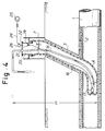
- Fig. 4 is a view similar as Fig. 1 illustrating another step of the branch pipe lining method of the invention;
- Fig. 5 is a view similar as Fig. 1 illustrating another step of the branch pipe lining method of the invention;
- Fig. 6 is a view similar as Fig. 1 illustrating another step of the branch pipe lining method of the invention;
- Fig. 7 is a view similar as Fig. 1 illustrating another step of the branch pipe lining method of the invention;
- Fig. 8 is an enlarged view of the portion A of Fig. 7;
- Fig. 9 is a set of illustrations showing different manners of how the head portion of a branch pipe liner bag is dislocated to change eversion direction;
- Fig. 10 is a sectional perspective view of a branch pipe liner bag according to an embodiment of the invention;
- Fig. 11 is a sectional perspective view of a branch pipe liner bag according another embodiment of the invention; and
- Fig. 12 is a sectional side view of a site containing a branched main pipe, illustrating a conventional method lining the branch pipe.
- Next, embodiments of the invention will be described with reference to the attached drawings.
- In Fig. 1, which schematically shows a site of the pipe repair operation,
reference numeral 1 designates an underground main pipe, which is already internally lined with aliner 2 of a hardened material by the conventional lining method. That portion of theliner 2 has been cut off where themain pipe 1 opens into abranch pipe 3; thus, thebranch pipe 3 communicates with themain pipe 1 via this port. - To line the
branch pipe 3, a branchpipe liner bag 4, shown in Fig. 10, is used. But, thispipe liner bag 4 itself must be described in detail first. A rectangular nonwoven resin-absorbent fabric 5 of polyester felt is sewed into a tubular shape. Thetubular fabric 5 is then externally coated with an air- and water-tightplastic film 6 and is soaked with a thermosetting resin. (Thishermetic film 6 may be made of polyurethane, polyethylene, polyethylene/nylon co-polymer, or polyvinyl chloride resin, and thefabric 5 may be made of polyester, polypropylene, or acrylic resin.) - As shown in Fig. 1, the tubular
pipe liner bag 4 to be inserted in thebranch pipe 3 has its tail end closed, and the front end everted and anchored sealingly about the outside of the bottom rim of atubular pressure cap 7a of aframe 7 installed on the ground. - Then, water is poured down the
pressure cap 7a from awater charge hose 8, and the water pressure (gravity) forces theliner bag 4 to roll inside out in thebranch pipe 3 and to proceed toward themain pipe 1. - Incidentally, the length of the
liner bag 4 is so designed that when the entire length of thebag 4 were everted without being stopped the head of the thoroughly evertedbag 4 would extend beyond the port of themain pipe 1 by at least one meter. Therefore, when theliner bag 4 is everted down thebranch pipe 3, the everting head of theliner bag 4 would hit upon the inner wall of themain pipe 1, as shown in Fig. 2, for even when the diameter of the themain pipe 1 is greater than one meter theliner bag 4 would more or less expand lengthwise as it is pressed down. Thus, the eversion of theliner bag 4 is stopped and someportion 4a of theliner bag 4 remains uneverted. - Now, in the present embodiment, an on-the-
sleigh robot 9 is introduced in themain pipe 1, as shown in Fig. 2. Pull ropes are tied to thisrobot 9 to pull it in either direction in themain pipe 1. Therobot 9 is equipped with a hydraulically-operated cutter and a hydraulically-operatedpiston cylinder 10. When the robot is brought to an appropriate position relative to thehead 4b of theliner bag 4, as shown in Fig. 2, thepiston cylinder 10 is operated to throw out itspiston rod 10a to push thehead 4b of theliner bag 4 leftward, as seen in Fig. 2; whereupon the strandedhead 4b of theliner bag 4 is turned to look leftward (downstream) and finds a room to evert itself further on in this direction, which it does until all theuneverted portion 4a of thebag 4 is everted (Fig. 3). The turnedhead 4b of theliner bag 4 is drawn in the broken line in Fig. 2. - Of course, there can be conceived various alternatives to this
robot 9 as a means to dislocate the strandedhead 4b of theliner bag 4, and Fig. 9 shows some of them which the present inventor tried and found practical. It is probably possible for a skilled person in this art to come up with an even better device than any of these; however, so long as the result is to turn the head of theliner bag 4 downstream, the device is within the realm of this invention. In other words, the present invention lies in the idea of turning the deadlocked head of theliner bag 4 to the downstream direction of themain pipe 1. - Method (a) of Fig. 9 utilizes a
pull rope 11 with ahook block 12 tied halfway to it, and this rope is passed through themain pipe 1 before theliner bag 4 is inserted in thebranch pipe 3. When thehead 4b of the evertedliner bag 4 hits upon the inner wall of themain pipe 1, therope 11 is pulled downstream and thehook block 12 engages with thehead 4b to dislocate and turn it. - Method (b) utilizes an
air bag 13 and apull rope 14, and when thehead 4b of the evertedliner bag 4 lands on theair bag 13, theair bag 13 is inflated and therope 14 is pulled downstream together with theair bag 13 and thehead 4b is dislocated and turned. - Method (c) utilizes a pressurized flow of a fluid such as water and air. When the
head 4b of the evertedliner bag 4 hits upon the inner wall of themain pipe 1, a fluid is forced downstream from the right end of themain pipe 1, as seen in (c) of Fig. 9, and the evertedliner bag 4 is pressed to turn it head 4b. - When the stranded
head 4b of theliner bag 4 is thus dislocated and turned downstream, the water pressure causes thehead 4b to start everting until all theuneverted portion 4a is everted, as shown in Fig. 3, and there remains nouneverted portion 4a. - Incidentally, in Fig. 2,
reference numeral 15 designates a hot water hose. One end of thehot water hose 15 is tied to arope 16, which is passed through aring 17 provided at the tail end of theuneverted portion 4a of theliner bag 4, and the free end of which is retained on the ground. When theliner bag 4 is everted into thebranch pipe 3 and hits upon the inner wall of themain pipe 1, therope 16 is pulled up so that thehose 15 is drawn into the evertedliner bag 4.
When the entire length of the branchpipe liner bag 4 is everted as described above, the free end of therope 16 is pulled up so that thehot water hose 15 is drawn deep to almost reach thering 17 provided at the tail end of theliner bag 4, and so as not to allow thehose 15 to recede, the ringed free end of therope 16 is hooked on ahook 21 provided on the inner wall of thepressure cap 7a, as shown in Fig. 3. Also, the open top of thepressure cap 7a of theframe 7 is closed with alid 22 so that anair room 23 is enclosed defined by thepressure cap 7a, the branchpipe liner bag 4 and the hot water. Anair hose 24 leading out from anair compressor 25 is plugged in a port of thelid 22 to communicate theair room 23 with theair compressor 25. Incidentally, another hole of thelid 22 is plugged with apressure gauge 26, as shown in Fig. 3. - Thus, when the entire length of the branch
pipe liner bag 4 is everted as described above, thecompressor 25 is operated to force air into theair room 23 and the pressure on the water in theliner bag 4 is maintained at a constant value so that thebag 4 is kept inflated and pressed against the inner wall of thebranch pipe 3, as shown in Fig. 3. At this juncture, the hot water heated in aboiler 18 installed on the ground is forced into thehot water hose 15 by means of ahot water pump 19 and is supplied into the branchpipe liner bag 4. After heating the branchpipe liner bag 4, the hot water is drawn up into anotherhot water hose 20 and returned to theboiler 18, where the lukewarm water is heated up again. Then, the heated water is sent back to the branchpipe liner bag 4 to cure the thermosetting resin soaked in the thickness of the branchpipe liner bag 4, and this circulation is continued until theliner bag 4 is sufficiently heated. - Incidentally, since there has remained no
uneverted tail 4a of theliner bag 4, thehot water hose 15 can be drawn as deep as thehead portion 4b of theliner bag 4 so that the hot water circulates well into the head port: of theliner bag 4; as a result, thehead portion 4b cures thoroughly and uniformly and there occur no incompletely cured regions. - Thus, when the entire length of the branch
pipe liner bag 4 is uniformly hardened, as described above, theair compressor 25 is operated to increase its force with which the air is supplied to theair room 23 via theair hose 24; as a result the pressure in theair room 23 is increased and the pressure on the water in theliner bag 4 is heightened so much so that the hot water in the branchpipe liner bag 4 is forced to flow backward in thehot water hose 15 and is discharged on the ground, and this operation of theair compressor 25 is continued until the last of the water in the branchpipe liner bag 4 is forced out. Incidentally, in order to force out the entire amount of hot water from the branchpipe liner bag 4 it is necessary to maintain the pressure P inside theair room 23 at a value greater than g H (wherein g is the specific gravity of the hot water and H is the water head, as shown in Fig. 4). - When all the amount of hot water is removed from the branch
pipe liner bag 3, as described above, the ringed end of therope 16, which was hooked on thehook 21 is unhooked from thehook 21, and theframe 7 is removed from abovebranch pipe 3, and, as shown in Fig. 5, thehot water hose 15 is pulled up and removed frombranch pipe 3. Incidentally, as described before, therope 16 is passed through thering 17 provided at the tail end of the branchpipe liner bag 4 so that when thehot water hose 15 is pulled up, therope 16 easily passes through thering 17 so that thehot water hose 15 is easily pulled away from thebranch pipe 3. When thehot water hose 15 is removed, the unnecessary portion of the hardened branchpipe liner bag 4 is cut off by means of the on-the-sleigh robot 9, which is introduced in themain pipe 1, the unnecessary portion being that portion which extends into themain pipe 1. - Besides the hydraulically-operated
piston cylinder 10, the on-the-sleigh robot 9 is equipped with a hydraulically-operatedmotor 27, aTV camera 28, etc., and the unnecessary portion of the branchpipe liner bag 4 is cut off by arotary cutter 29 which is locked about the output shaft of themotor 27. More descriptively, while observing the position of the unnecessary portion of theliner bag 4 by means of theTV camera 28, the operator on the ground causes therobot 9 to move to and fro by pulling and letting go thepull ropes 30 until therobot 9 assumes a desirable position relative to the unnecessary portion of theliner bag 4; then, therotary cutter 29 is turned at a high speed and therobot 9 is pulled downstream slowly, whereupon thecutter 29 cuts in the unnecessary portion of theliner bag 4, and this cutting is continued until the last remnant of the unnecessary portion is removed. Since there is no uncured gluey region in the branchpipe liner bag 4, the saw teeth of thecutter 29 do not clog, and hence the cutting operation can be conducted easily and smoothly. - This cutting operation completes the series of the lining operation, and as the result, the inner wall of the
branch pipe 3 is lined with the curedbranch pipe liner 4, as shown in Fig. 7. Incidentally, the juncture where thebranch pipe liner 4 and themain pipe liner 2 meet each other is merged to form a continuous liner, as shown in Fig. 8, by virtue of the bonding function of the thermosetting resin impregnated in thebranch pipe liner 4. Incidentally, in Fig. 8,reference numeral 6 designates a plastic film which covers up the inner surface of thebranch pipe liner 4, andreference numeral 31 designates a plastic film which covers up the inner surface of themain pipe liner 2. - Now, in the above-described embodiment, the
branch pipe 3 is lined in accordance with the method of the invention after themain pipe 1 is lined beforehand. Since the inner wall of themain pipe 1 is covered with theplastic film 2, the head of the evertedliner bag 4 does not stick to the inner wall of themain pipe 1, when it hits upon the inner wall of themain pipe 1, owing to the surface releasability of theplastic film 2. In the case where only thebranch pipe 3 is to be lined, it is also possible to adopt the method of the present invention; but if a similar branch pipe liner bag as theliner bag 4 is used, then when the eversion head of theeverting liner bag 4 hits upon the inner wall of themain pipe 1, which is not lined with theliner 2, and therefore, not covered up with theplastic film 2, the eversion head of the branchpipe liner bag 4 would stick to the inner wall of themain pipe 1. To prevent this inconvenience, a branchpipe liner bag 34 as shown in Fig. 11 ought to be used. - Fig. 11 is a sectional perspective view of a branch
pipe liner bag 34 before eversion, and the branchpipe liner bag 34 is internally coated with a highlyimpermeable barrier film 35. Incidentally, in Fig. 11,reference numeral 5 designates a tubular nonwoven resin-absorbent fabric of polyester felt, and, like that of the branchpipe liner bag 4, this fabric is impregnated with thermosetting resin. - Thus, if the branch
pipe liner bag 34 is used to line thebranch pipe 3 with, the branchpipe liner bag 34 when it is everted will have a non-adhesive external surface consisting of thebarrier film 35, so that the eversion head of the branchpipe liner bag 34 does not stick to the inner wall of themain pipe 1. Thus, the unnecessary portion of the evertedliner bag 34 will be easily removed. - As is clear from the above explanation, according to the invention, although the branch pipe liner bag will be kept from everting as its eversion head is stopped by the inner wall of the main pipe, the eversion head is forced to turn downstream, so that the branch pipe liner bag can be eventually everted completely. Therefore, no portion will remain uneverted of the liner bag. As a result, when hot water, for example, is supplied into the branch pipe liner bag which has been inserted in the branch pipe as described above, the hot water will circulate well into the fore end of the liner bag and causes the thermosetting resin soaked in the liner bag to promptly harden thoroughly and uniformly, so that there occur scarce regions where the branch pipe liner bag is only half hardened.
- Also, since there remains no uneverted portion of the hardened branch pipe liner bag, the subsequent operation of cutting away the portion of the liner bag that extends into the main pipe is made easy.
- While the invention has been described in its preferred embodiments, it is to be understood that modifications will occur to those skilled in the art without departing from the spirit of the invention. For instance, the thermosetting resin may be replaced by another hardenable resin such as photosetting resin. The scope of the invention is therefore to be determined solely by the appended claims.
Claims (8)
- A method for lining a branch pipe (3) branching off a main pipe (1), comprising the steps of: (a) preparing a tubular liner bag (4) by sewing a rectangular nonwoven resin-absorbent fabric (5) into a tubular shape with one end closed and cutting it to a length substantially greater than the length of the branch pipe to be lined; (b) attaching an impermeable plastic film over the external surface of said tubular liner bag; (c) soaking said nonwoven resin-absorbent fabric with a hardenable fluid resin; (d) everting said liner bag into the branch pipe from the ground to the main pipe by means of a fluid pressure until the eversion head (4b) of the liner bag is stopped by the inner wall of the main pipe; (e) forcing said eversion head of the liner bag to turn downstream in the main pipe, thus allowing the liner bag to evert entirely; (f) hardening said hardenable fluid resin while inflating said liner bag by means of the fluid pressure; and (g) removing that portion of said liner bag which protrudes into said main pipe.
- A method as claimed in Claim 1, characterized in that prior to step (d) the main pipe (1) is first lined with a liner (2) and that portion of the liner which closes the hole to the branch pipe (3) is removed.
- A method as claimed in Claim 1 or 2, characterized in that the inner surface of said liner bag (4) before eversion is covered with an impermeable barrier film.
- A method as claimed in any of Claims 1 to 3, characterized in that in step (g) the removal of said portion of the liner bag (4) is conducted by means of a rotary cutter (29) driven by a motor (27) and installed on a robot (9) which can reciprocate freely in the main pipe (1).
- A method as claimed in any of Claims 1 to 4, characterized in that in step (e) a pull rope (11) with a hook block (12) tied halfway to it is passed in the main pipe (1) beforehand such that the eversion head (4b) of the liner bag (4) lands on the rope at a location downstream to the hook block, and the pull rope is pulled downstream so as to force the eversion head to turn.
- A method as claimed in any of Claims 1 to 4, characterized in that in step (e) a pull rope (14) with an air bag (13) tied halfway to it is passed in the main pipe (1) beforehand such that the eversion head (4b) of the liner bag (4) lands on the air bag, and the pull rope is pulled downstream after the air bag is inflated so as to force the eversion head to turn.
- A method as claimed in any of Claims 1 to 4, characterized in that in step (e) a pressurized flow of a fluid is applied downstream to the eversion head (4b) so as to force the eversion head to turn.
- A method as claimed in any of Claims 1 to 7, characterized in that said hardenable fluid resin is a thermosetting resin.
Applications Claiming Priority (2)
| Application Number | Priority Date | Filing Date | Title |
|---|---|---|---|
| JP21431/93 | 1993-02-09 | ||
| JP5021431A JPH0775866B2 (en) | 1993-02-09 | 1993-02-09 | Branch pipe lining method |
Publications (2)
| Publication Number | Publication Date |
|---|---|
| EP0610620A1 true EP0610620A1 (en) | 1994-08-17 |
| EP0610620B1 EP0610620B1 (en) | 1996-09-04 |
Family
ID=12054803
Family Applications (1)
| Application Number | Title | Priority Date | Filing Date |
|---|---|---|---|
| EP93308428A Expired - Lifetime EP0610620B1 (en) | 1993-02-09 | 1993-10-22 | A method for lining a branch pipe |
Country Status (7)
| Country | Link |
|---|---|
| US (1) | US5356502A (en) |
| EP (1) | EP0610620B1 (en) |
| JP (1) | JPH0775866B2 (en) |
| KR (1) | KR0178145B1 (en) |
| DE (1) | DE69304509T2 (en) |
| DK (1) | DK0610620T3 (en) |
| MY (1) | MY109465A (en) |
Cited By (3)
| Publication number | Priority date | Publication date | Assignee | Title |
|---|---|---|---|---|
| WO1996031727A1 (en) * | 1995-04-05 | 1996-10-10 | Rice, Doreen | Branched sewer re-lining |
| CN105697933A (en) * | 2016-03-29 | 2016-06-22 | 华北水利水电大学 | Rainfall and sewage pipe leakage prevention device, manufacturing method and use method thereof |
| EP3156711A1 (en) * | 2015-10-14 | 2017-04-19 | ULC Robotics, Inc. | Method for pipe insertion in a pipeline |
Families Citing this family (16)
| Publication number | Priority date | Publication date | Assignee | Title |
|---|---|---|---|---|
| US5674030A (en) * | 1991-08-27 | 1997-10-07 | Sika Equipment Ag. | Device and method for repairing building branch lines in inacessible sewer mains |
| JP2530552B2 (en) * | 1993-03-23 | 1996-09-04 | 株式会社湘南合成樹脂製作所 | Branch pipe lining method |
| JP2702086B2 (en) * | 1995-02-13 | 1998-01-21 | 株式会社湘南合成樹脂製作所 | Manufacturing method of pipe lining material |
| JP2719312B2 (en) * | 1995-03-23 | 1998-02-25 | 株式会社湘南合成樹脂製作所 | Joining method of pipe lining material |
| GB9510433D0 (en) * | 1995-05-22 | 1995-07-19 | British Gas Plc | Installing pipes |
| JP2667796B2 (en) * | 1995-07-07 | 1997-10-27 | 株式会社湘南合成樹脂製作所 | Pipe lining method |
| US5879501A (en) * | 1996-12-19 | 1999-03-09 | Illinois Tool Works, Inc. | Method of sealing sewer systems |
| CA2354226A1 (en) | 2001-01-31 | 2002-07-31 | Cal Holland | Robotic apparatus and method for non-destructive maintenance of intersecting conduits |
| US20050281970A1 (en) * | 2004-06-16 | 2005-12-22 | Lamarca Louis J Ii | Lateral liner substrates |
| TW200613677A (en) * | 2004-10-27 | 2006-05-01 | Shonan Gosei Jushi Seisakusho | Lateral pipe lining material and lateral pipe lining method |
| JP2007283572A (en) * | 2006-04-14 | 2007-11-01 | Shonan Plastic Mfg Co Ltd | Pipe lining method |
| JP2008162033A (en) * | 2006-12-27 | 2008-07-17 | Shikoku Kankyo Seibi Kogyo Kk | Lining material for branch pipe and method for lining branch pipe |
| JP2008238657A (en) * | 2007-03-28 | 2008-10-09 | Shonan Plastic Mfg Co Ltd | Electric heating device and pipeline lining method using the device |
| WO2016087707A1 (en) * | 2014-12-04 | 2016-06-09 | Consti Talotekniikka Oy | Method for renovating a branch point in a pipeline under renovation |
| KR102239106B1 (en) * | 2020-09-04 | 2021-04-12 | 이수기공(주) | Method of regeneration of old pipes including branch pipe regeneration step by PE lining |
| DE102022121917A1 (en) * | 2022-08-30 | 2024-02-29 | Brawo Systems Gmbh | Device and method for curing a liner drawn into a pipe using an inversion process |
Citations (4)
| Publication number | Priority date | Publication date | Assignee | Title |
|---|---|---|---|---|
| US4786345A (en) * | 1984-03-24 | 1988-11-22 | Instituform Licencees B.V. | Method of lining a passageway |
| JPS63286326A (en) * | 1987-05-20 | 1988-11-24 | Toubu Kuriinaa Service:Kk | Maintenance work for branch pipe |
| GB2213230A (en) * | 1987-12-28 | 1989-08-09 | Osaka Bosui Kensetsusha Kk | Lining branch pipes |
| US5108533A (en) * | 1989-10-10 | 1992-04-28 | Long Technologies, Inc. | Method and combination for installing a liner within a service pipe transversely connected to a main pipe |
Family Cites Families (9)
| Publication number | Priority date | Publication date | Assignee | Title |
|---|---|---|---|---|
| US4366012A (en) * | 1981-02-05 | 1982-12-28 | Insituform International Inc. | Impregnation process |
| US4434115A (en) * | 1981-02-18 | 1984-02-28 | Insituform International, Inc. | Method for remote lining of side connections |
| GB8400233D0 (en) * | 1984-01-05 | 1984-02-08 | Edgealpha Ltd | Lining pipelines and passageways |
| GB2157796B (en) * | 1984-04-17 | 1987-07-08 | Nigel Rice | Sewer relining |
| JPS61100437A (en) * | 1984-10-24 | 1986-05-19 | Osaka Gas Co Ltd | Method of lining branch pipe of city gas conduit |
| GB8609307D0 (en) * | 1986-04-16 | 1986-05-21 | Insituform Group Ltd | Lining of piplines |
| JPH0198325A (en) * | 1987-10-09 | 1989-04-17 | Mazda Motor Corp | On-vehicle receiver |
| JPH0717012B2 (en) * | 1989-09-05 | 1995-03-01 | 東京瓦斯株式会社 | Non-drilled tube inversion lining method for conduit |
| JPH07121552B2 (en) * | 1991-05-31 | 1995-12-25 | 株式会社ゲット | Branch pipe lining method |
-
1993
- 1993-02-09 JP JP5021431A patent/JPH0775866B2/en not_active Expired - Fee Related
- 1993-07-12 KR KR1019930013042A patent/KR0178145B1/en not_active IP Right Cessation
- 1993-10-22 EP EP93308428A patent/EP0610620B1/en not_active Expired - Lifetime
- 1993-10-22 US US08/139,671 patent/US5356502A/en not_active Expired - Fee Related
- 1993-10-22 DE DE69304509T patent/DE69304509T2/en not_active Expired - Fee Related
- 1993-10-22 DK DK93308428.7T patent/DK0610620T3/en active
- 1993-12-11 MY MYPI93002675A patent/MY109465A/en unknown
Patent Citations (4)
| Publication number | Priority date | Publication date | Assignee | Title |
|---|---|---|---|---|
| US4786345A (en) * | 1984-03-24 | 1988-11-22 | Instituform Licencees B.V. | Method of lining a passageway |
| JPS63286326A (en) * | 1987-05-20 | 1988-11-24 | Toubu Kuriinaa Service:Kk | Maintenance work for branch pipe |
| GB2213230A (en) * | 1987-12-28 | 1989-08-09 | Osaka Bosui Kensetsusha Kk | Lining branch pipes |
| US5108533A (en) * | 1989-10-10 | 1992-04-28 | Long Technologies, Inc. | Method and combination for installing a liner within a service pipe transversely connected to a main pipe |
Cited By (6)
| Publication number | Priority date | Publication date | Assignee | Title |
|---|---|---|---|---|
| WO1996031727A1 (en) * | 1995-04-05 | 1996-10-10 | Rice, Doreen | Branched sewer re-lining |
| US5954903A (en) * | 1995-04-05 | 1999-09-21 | Rice; Nigel Leonard | Branched sewer re-lining |
| EP3156711A1 (en) * | 2015-10-14 | 2017-04-19 | ULC Robotics, Inc. | Method for pipe insertion in a pipeline |
| US9927059B2 (en) | 2015-10-14 | 2018-03-27 | Ulc Robotics, Inc. | System and method for pipe insertion in a pipeline |
| US10309576B2 (en) | 2015-10-14 | 2019-06-04 | Ulc Robotics, Inc. | System and method for pipe insertion in a pipeline |
| CN105697933A (en) * | 2016-03-29 | 2016-06-22 | 华北水利水电大学 | Rainfall and sewage pipe leakage prevention device, manufacturing method and use method thereof |
Also Published As
| Publication number | Publication date |
|---|---|
| JPH0775866B2 (en) | 1995-08-16 |
| DE69304509D1 (en) | 1996-10-10 |
| JPH06234160A (en) | 1994-08-23 |
| KR0178145B1 (en) | 1999-05-15 |
| MY109465A (en) | 1997-01-31 |
| EP0610620B1 (en) | 1996-09-04 |
| US5356502A (en) | 1994-10-18 |
| KR940019448A (en) | 1994-09-14 |
| DK0610620T3 (en) | 1996-09-23 |
| DE69304509T2 (en) | 1997-02-20 |
Similar Documents
| Publication | Publication Date | Title |
|---|---|---|
| US5356502A (en) | Method for lining a branch pipe | |
| AU708872B2 (en) | A method for lining a bent pipe | |
| US5454401A (en) | Method of lining a branch pipe | |
| EP0620102B1 (en) | Branch pipe lining method and liner | |
| US5549856A (en) | Method of repairing a pipeline with an injected resin | |
| US6024910A (en) | Method for lining a tubular conduit | |
| US5490964A (en) | Method and device for repairing a tubular conduit | |
| US6206993B1 (en) | Method and apparatus for providing a tubular material within a pipeline | |
| US5280811A (en) | Method of softlining sewer rehabilitation | |
| US5329063A (en) | Liner assembly for lining branch pipes and a method for manufacturing the liner assembly | |
| US6056017A (en) | Pipe lining method | |
| EP0978681B1 (en) | Branch pipe liner bag and pipe lining method | |
| EP0620104A2 (en) | Pipe liner bag, manufacturing method therefor and pipe repair method | |
| EP0938964A2 (en) | Branch pipe liner bag and branch pipe lining method | |
| US6682668B1 (en) | Installation of cured in place liners with an endless reusable inflation bladder and installation apparatus | |
| US5486332A (en) | Method for everting a tubular liner bag | |
| EP0620101B1 (en) | Method and apparatus for lining a branch pipe | |
| EP0797042B1 (en) | An apparatus and a method for lining an underground pipe | |
| KR19990013994A (en) | Target jig and pipe lining method | |
| EP0911568A2 (en) | A branch pipe lining assembly and a pipe lining method |
Legal Events
| Date | Code | Title | Description |
|---|---|---|---|
| PUAI | Public reference made under article 153(3) epc to a published international application that has entered the european phase |
Free format text: ORIGINAL CODE: 0009012 |
|
| AK | Designated contracting states |
Kind code of ref document: A1 Designated state(s): DE DK FR GB |
|
| 17P | Request for examination filed |
Effective date: 19950124 |
|
| 17Q | First examination report despatched |
Effective date: 19950921 |
|
| GRAH | Despatch of communication of intention to grant a patent |
Free format text: ORIGINAL CODE: EPIDOS IGRA |
|
| GRAH | Despatch of communication of intention to grant a patent |
Free format text: ORIGINAL CODE: EPIDOS IGRA |
|
| GRAA | (expected) grant |
Free format text: ORIGINAL CODE: 0009210 |
|
| AK | Designated contracting states |
Kind code of ref document: B1 Designated state(s): DE DK FR GB |
|
| REG | Reference to a national code |
Ref country code: DK Ref legal event code: T3 |
|
| REF | Corresponds to: |
Ref document number: 69304509 Country of ref document: DE Date of ref document: 19961010 |
|
| ET | Fr: translation filed |
Free format text: CORRECTIONS |
|
| PLBE | No opposition filed within time limit |
Free format text: ORIGINAL CODE: 0009261 |
|
| STAA | Information on the status of an ep patent application or granted ep patent |
Free format text: STATUS: NO OPPOSITION FILED WITHIN TIME LIMIT |
|
| 26N | No opposition filed | ||
| PGFP | Annual fee paid to national office [announced via postgrant information from national office to epo] |
Ref country code: FR Payment date: 20011010 Year of fee payment: 9 |
|
| PGFP | Annual fee paid to national office [announced via postgrant information from national office to epo] |
Ref country code: DK Payment date: 20011012 Year of fee payment: 9 |
|
| PGFP | Annual fee paid to national office [announced via postgrant information from national office to epo] |
Ref country code: GB Payment date: 20011024 Year of fee payment: 9 |
|
| PGFP | Annual fee paid to national office [announced via postgrant information from national office to epo] |
Ref country code: DE Payment date: 20011105 Year of fee payment: 9 |
|
| REG | Reference to a national code |
Ref country code: GB Ref legal event code: IF02 |
|
| PG25 | Lapsed in a contracting state [announced via postgrant information from national office to epo] |
Ref country code: GB Free format text: LAPSE BECAUSE OF NON-PAYMENT OF DUE FEES Effective date: 20021022 |
|
| PG25 | Lapsed in a contracting state [announced via postgrant information from national office to epo] |
Ref country code: DK Free format text: LAPSE BECAUSE OF NON-PAYMENT OF DUE FEES Effective date: 20021031 |
|
| PG25 | Lapsed in a contracting state [announced via postgrant information from national office to epo] |
Ref country code: DE Free format text: LAPSE BECAUSE OF NON-PAYMENT OF DUE FEES Effective date: 20030501 |
|
| REG | Reference to a national code |
Ref country code: DK Ref legal event code: EBP |
|
| GBPC | Gb: european patent ceased through non-payment of renewal fee |
Effective date: 20021022 |
|
| PG25 | Lapsed in a contracting state [announced via postgrant information from national office to epo] |
Ref country code: FR Free format text: LAPSE BECAUSE OF NON-PAYMENT OF DUE FEES Effective date: 20030630 |
|
| REG | Reference to a national code |
Ref country code: FR Ref legal event code: ST |