EP0610111A1 - Flüssigkeitsverteiler Ventil - Google Patents
Flüssigkeitsverteiler Ventil Download PDFInfo
- Publication number
- EP0610111A1 EP0610111A1 EP94400120A EP94400120A EP0610111A1 EP 0610111 A1 EP0610111 A1 EP 0610111A1 EP 94400120 A EP94400120 A EP 94400120A EP 94400120 A EP94400120 A EP 94400120A EP 0610111 A1 EP0610111 A1 EP 0610111A1
- Authority
- EP
- European Patent Office
- Prior art keywords
- shutter
- primary
- face
- valve body
- spherical annular
- Prior art date
- Legal status (The legal status is an assumption and is not a legal conclusion. Google has not performed a legal analysis and makes no representation as to the accuracy of the status listed.)
- Granted
Links
Images

Classifications
-
- F—MECHANICAL ENGINEERING; LIGHTING; HEATING; WEAPONS; BLASTING
- F16—ENGINEERING ELEMENTS AND UNITS; GENERAL MEASURES FOR PRODUCING AND MAINTAINING EFFECTIVE FUNCTIONING OF MACHINES OR INSTALLATIONS; THERMAL INSULATION IN GENERAL
- F16K—VALVES; TAPS; COCKS; ACTUATING-FLOATS; DEVICES FOR VENTING OR AERATING
- F16K1/00—Lift valves or globe valves, i.e. cut-off apparatus with closure members having at least a component of their opening and closing motion perpendicular to the closing faces
- F16K1/32—Details
- F16K1/34—Cutting-off parts, e.g. valve members, seats
- F16K1/44—Details of seats or valve members of double-seat valves
- F16K1/443—Details of seats or valve members of double-seat valves the seats being in series
-
- Y—GENERAL TAGGING OF NEW TECHNOLOGICAL DEVELOPMENTS; GENERAL TAGGING OF CROSS-SECTIONAL TECHNOLOGIES SPANNING OVER SEVERAL SECTIONS OF THE IPC; TECHNICAL SUBJECTS COVERED BY FORMER USPC CROSS-REFERENCE ART COLLECTIONS [XRACs] AND DIGESTS
- Y10—TECHNICAL SUBJECTS COVERED BY FORMER USPC
- Y10T—TECHNICAL SUBJECTS COVERED BY FORMER US CLASSIFICATION
- Y10T137/00—Fluid handling
- Y10T137/8593—Systems
- Y10T137/87917—Flow path with serial valves and/or closures
- Y10T137/88038—One valve head carries other valve head
-
- Y—GENERAL TAGGING OF NEW TECHNOLOGICAL DEVELOPMENTS; GENERAL TAGGING OF CROSS-SECTIONAL TECHNOLOGIES SPANNING OVER SEVERAL SECTIONS OF THE IPC; TECHNICAL SUBJECTS COVERED BY FORMER USPC CROSS-REFERENCE ART COLLECTIONS [XRACs] AND DIGESTS
- Y10—TECHNICAL SUBJECTS COVERED BY FORMER USPC
- Y10T—TECHNICAL SUBJECTS COVERED BY FORMER US CLASSIFICATION
- Y10T137/00—Fluid handling
- Y10T137/8593—Systems
- Y10T137/87917—Flow path with serial valves and/or closures
- Y10T137/88046—Biased valve with external operator
Definitions
- a fluid distribution valve interposed between a first and a second enclosure, intended to selectively bring into mutual communication and the isolation of the two enclosures, and, comprising a valve body and a movable shutter guided in translation in the valve body along a sliding axis, the valve body comprising a passage connecting the first and second enclosures and opening into the second enclosure by an opening delimited by an edge, and, the shutter being provided with a face sealing capable of being placed in sealing abutment on said edge.
- the shutter is made of a material of great hardness, such as steel, the valve body on the other hand being made of a less hard material, such as a light alloy.
- the sealing face of the obturator is designed to be applied to the edge of the valve body, which is a sharp edge, without burrs, so that any foreign bodies, trapped between the edge shutter, can be cut to ensure sealing.
- the seal obtained is poor. This is due to the fact that two functions are performed by the aforementioned sharp edge: on the one hand, this edge makes it possible to cut the undesirable foreign bodies, on the other hand, the sealing is carried out at its level.
- the invention intends to remedy this state of affairs by separating the means provided for performing the two aforementioned functions.
- the fluid distribution valve previously defined comprises the following provisions: A) the valve body further comprises a spherical annular face with an axis of revolution parallel to the sliding axis and disposed inside the second enclosure, and, B) the obturator comprises, on the one hand, a primary obturator, which comprises said sealing face capable of being placed in leaktight abutment on said edge, on the other hand, a secondary obturator which comprises a spherical annular segment, which is coupled resiliently to the primary obturator, and which is capable of being placed in leaktight support on said spherical annular face of the valve body.
- the main advantage lies in the fact that the part of the valve, which cuts the undesirable foreign bodies, already provides a seal between the body and the valve shutter. However, its sealing function is also doubled between the face and the spherical annular segment, which gives the assurance of obtaining a real seal. In addition, the actual guiding of the primary shutter is improved, which reduces the risks of tilting known previously and is likely to improve the seal obtained between the primary shutter and the body of the valve.
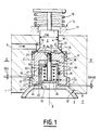
- the secondary obturator 3 comprises a sleeve 26, introduced into the bore 25 of the primary obturator having an external cylindrical face 27, disposed facing the bore 25, a seal 28 being disposed between the bore 25 and the external face 27 of the sleeve, the latter comprising, at one of its ends, a transverse wall 29 provided with a through hole 30, and, at the other end, an annular segment 31, of axis 8 , of the same radius as the spherical annular face 12 of the valve body 2, and capable of being in leaktight support (and of the "ball-and-socket" type) on said face 12, a recess 32 extending from the transverse wall 29 for lead into the second enclosure 11.
- a screw partially contained in the recess 32, has a rod 33, which passes through the hole 30 and is screwed into a thread 34 which comprises the primary shutter 2, and has a screw head 35, a spring 36 being interposed between the transverse wall 29 and the screw head 35 and tending to drive the sleeve 26 inside the bore 25, and, by this means, to seal the spherical annular segment 31 on the spherical annular face 12.
- a second seal is produced by the swiveling support of the spherical annular segment 31 on the spherical annular face 12.
- the second seal, between the spherical annular segment 31 and the spherical annular face 12 would nevertheless be produced.
- the seal 28 prevents the flow of an uncontrolled flow between the volumes 39 and 37, and, through the clearances J and K, between the volume 39 and the second enclosure 11, in the obturation configuration. between segment 31 and face 12 spherical annulars. But to do this, it is necessary that D22 is greater than D24 / 40. It is indeed necessary that the faces 24, 40 come into abutment abutment before the grooves 21 do not open into the volume 39, then into the second enclosure 11, this so that the fluid flow is correctly dosed.
- the shutter slides as a whole (shutter primary 2 and secondary shutter 3) parallel to axis 8.
- the advantage of the valve described resides both in the redundancy of the seals produced, a condition for obtaining a perfect overall seal, and in the independence of the seals from one another.
- the valve can in particular be used in the fuel distribution circuits to the injectors of a turbine engine.
Applications Claiming Priority (2)
| Application Number | Priority Date | Filing Date | Title |
|---|---|---|---|
| FR9300509A FR2700597B1 (fr) | 1993-01-20 | 1993-01-20 | Clapet de distribution de fluide. |
| FR9300509 | 1993-01-20 |
Publications (2)
| Publication Number | Publication Date |
|---|---|
| EP0610111A1 true EP0610111A1 (de) | 1994-08-10 |
| EP0610111B1 EP0610111B1 (de) | 1997-06-04 |
Family
ID=9443191
Family Applications (1)
| Application Number | Title | Priority Date | Filing Date |
|---|---|---|---|
| EP94400120A Expired - Lifetime EP0610111B1 (de) | 1993-01-20 | 1994-01-20 | Flüssigkeitsverteiler Ventil |
Country Status (4)
| Country | Link |
|---|---|
| US (1) | US5333644A (de) |
| EP (1) | EP0610111B1 (de) |
| DE (1) | DE69403499T2 (de) |
| FR (1) | FR2700597B1 (de) |
Families Citing this family (4)
| Publication number | Priority date | Publication date | Assignee | Title |
|---|---|---|---|---|
| US5562121A (en) * | 1995-04-06 | 1996-10-08 | Allied Healthcare Products, Inc. | Gas delivery system with universal outlet |
| ATE354760T1 (de) | 1998-06-24 | 2007-03-15 | Beacon Medical Products Llc | Haltevorrichtung für einen gas-auslass-zylinder |
| US20040035478A1 (en) * | 2002-08-26 | 2004-02-26 | Herbst Robert J. | Spherical seat inlet/exhaust valve |
| US10518284B2 (en) * | 2015-08-04 | 2019-12-31 | Intelligent Agricultural Solutions Llc | Interactive liquid spraying system and method |
Citations (2)
| Publication number | Priority date | Publication date | Assignee | Title |
|---|---|---|---|---|
| DE2159110A1 (de) * | 1970-12-04 | 1972-06-29 | Magyar Vagon Es Gepgyar | Doppeltwirkendes Zentralventil zu Behältern, insbesondere zu Tankwagen |
| EP0098914A2 (de) * | 1982-07-14 | 1984-01-25 | C.P.F. S.p.A. | Doppelsitzventil für Druckbehälter |
Family Cites Families (5)
| Publication number | Priority date | Publication date | Assignee | Title |
|---|---|---|---|---|
| US2905487A (en) * | 1956-07-20 | 1959-09-22 | Herbert E Schifter | Double valve construction and the like |
| US3587634A (en) * | 1968-12-07 | 1971-06-28 | Phonix Armaturenwerke Bregel G | Fill and discharge valve with manual operation |
| JPS5235538Y2 (de) * | 1973-07-12 | 1977-08-13 | ||
| US4270571A (en) * | 1979-07-06 | 1981-06-02 | Pauliukonis Richard S | High pressure letdown valve |
| US4461318A (en) * | 1981-02-21 | 1984-07-24 | Holstein Und Kappert Gmbh | Double seat valve |
-
1993
- 1993-01-20 FR FR9300509A patent/FR2700597B1/fr not_active Expired - Fee Related
-
1994
- 1994-01-12 US US08/180,277 patent/US5333644A/en not_active Expired - Fee Related
- 1994-01-20 DE DE69403499T patent/DE69403499T2/de not_active Expired - Fee Related
- 1994-01-20 EP EP94400120A patent/EP0610111B1/de not_active Expired - Lifetime
Patent Citations (2)
| Publication number | Priority date | Publication date | Assignee | Title |
|---|---|---|---|---|
| DE2159110A1 (de) * | 1970-12-04 | 1972-06-29 | Magyar Vagon Es Gepgyar | Doppeltwirkendes Zentralventil zu Behältern, insbesondere zu Tankwagen |
| EP0098914A2 (de) * | 1982-07-14 | 1984-01-25 | C.P.F. S.p.A. | Doppelsitzventil für Druckbehälter |
Also Published As
| Publication number | Publication date |
|---|---|
| US5333644A (en) | 1994-08-02 |
| DE69403499D1 (de) | 1997-07-10 |
| FR2700597A1 (fr) | 1994-07-22 |
| EP0610111B1 (de) | 1997-06-04 |
| DE69403499T2 (de) | 1997-11-06 |
| FR2700597B1 (fr) | 1995-02-24 |
Similar Documents
| Publication | Publication Date | Title |
|---|---|---|
| EP0166641A1 (de) | Abdichtung zum stromauf- und stromabwärts fluiddichten Verschliessen eines Absperrelementes | |
| FR2517790A1 (fr) | Valve a levee equipee d'un soufflet entre l'obturateur et le corps, notamment pour fluides radioactifs ou toxiques | |
| CH631790A5 (fr) | Robinet a cartouche avec plaque rotative. | |
| EP0150643B1 (de) | Sicherheitsventil, insbesondere zum Schliessen einer Erdölbohrung | |
| EP3599408B1 (de) | Schnellkupplung für die lösbare verbindung von zwei rohren, durch die eine flüssigkeit unter druck fliesst | |
| LU86438A1 (fr) | Robinet a membrane | |
| CA1261311A (fr) | Dispositif d'obturation pour conduite vehiculant un fluide | |
| EP0610111B1 (de) | Flüssigkeitsverteiler Ventil | |
| FR2809461A1 (fr) | Actionneur pyrotechnique a membrane deformable | |
| FR2748566A1 (fr) | Dispositif de prise d'echantillon sur une canalisation | |
| CH655371A5 (fr) | Valve hydraulique. | |
| EP0473546B1 (de) | Mikrometrische Dosiervorrichtung | |
| EP1380779B1 (de) | Druckbegrenzungsventil | |
| EP1938010B1 (de) | Wasserhahn mit kugelförmigem drehverschluss | |
| EP3719608B1 (de) | Mischeinheit und mischbatterie, die eine solche mischeinheit umfasst | |
| EP0006770A1 (de) | Elektromagnetisches Ventil, insbesondere für einen Vergaser | |
| FR2464418A1 (fr) | Carter avec tampon d'etancheite pour dispositifs hydrauliques | |
| FR2491185A1 (fr) | Soupape de surpression reglable | |
| FR2813358A1 (fr) | Dispositif d'etancheite de palier pour des passages traversants | |
| FR2663394A1 (fr) | Dispositif obturateur a bille libre a jeux regles. | |
| FR2784439A1 (fr) | Agencement d'electrovanne susceptible d'etre fixee sur un support tel qu'un bloc hydraulique | |
| EP0098621B1 (de) | Mischventil für Warm- und Kaltwasser | |
| FR2549566A1 (fr) | Robinet a boisseau | |
| EP0993973B1 (de) | Steuervorrichtung für eine Radaufhängung eines Kraftfahrzeuges | |
| EP0039295A1 (de) | Auswahlventil zwischen drei Räumen von welchen zwei unter Druck sind |
Legal Events
| Date | Code | Title | Description |
|---|---|---|---|
| PUAI | Public reference made under article 153(3) epc to a published international application that has entered the european phase |
Free format text: ORIGINAL CODE: 0009012 |
|
| 17P | Request for examination filed |
Effective date: 19940204 |
|
| AK | Designated contracting states |
Kind code of ref document: A1 Designated state(s): DE FR GB |
|
| 17Q | First examination report despatched |
Effective date: 19960613 |
|
| GRAG | Despatch of communication of intention to grant |
Free format text: ORIGINAL CODE: EPIDOS AGRA |
|
| GRAH | Despatch of communication of intention to grant a patent |
Free format text: ORIGINAL CODE: EPIDOS IGRA |
|
| GRAH | Despatch of communication of intention to grant a patent |
Free format text: ORIGINAL CODE: EPIDOS IGRA |
|
| GRAA | (expected) grant |
Free format text: ORIGINAL CODE: 0009210 |
|
| AK | Designated contracting states |
Kind code of ref document: B1 Designated state(s): DE FR GB |
|
| REF | Corresponds to: |
Ref document number: 69403499 Country of ref document: DE Date of ref document: 19970710 |
|
| GBT | Gb: translation of ep patent filed (gb section 77(6)(a)/1977) |
Effective date: 19970625 |
|
| PLBE | No opposition filed within time limit |
Free format text: ORIGINAL CODE: 0009261 |
|
| STAA | Information on the status of an ep patent application or granted ep patent |
Free format text: STATUS: NO OPPOSITION FILED WITHIN TIME LIMIT |
|
| 26N | No opposition filed | ||
| REG | Reference to a national code |
Ref country code: GB Ref legal event code: IF02 |
|
| REG | Reference to a national code |
Ref country code: FR Ref legal event code: TP Ref country code: FR Ref legal event code: CD |
|
| PGFP | Annual fee paid to national office [announced via postgrant information from national office to epo] |
Ref country code: FR Payment date: 20041218 Year of fee payment: 12 |
|
| PGFP | Annual fee paid to national office [announced via postgrant information from national office to epo] |
Ref country code: GB Payment date: 20041224 Year of fee payment: 12 |
|
| PGFP | Annual fee paid to national office [announced via postgrant information from national office to epo] |
Ref country code: DE Payment date: 20041227 Year of fee payment: 12 |
|
| PG25 | Lapsed in a contracting state [announced via postgrant information from national office to epo] |
Ref country code: GB Free format text: LAPSE BECAUSE OF NON-PAYMENT OF DUE FEES Effective date: 20060120 |
|
| PG25 | Lapsed in a contracting state [announced via postgrant information from national office to epo] |
Ref country code: FR Free format text: LAPSE BECAUSE OF NON-PAYMENT OF DUE FEES Effective date: 20060131 |
|
| PG25 | Lapsed in a contracting state [announced via postgrant information from national office to epo] |
Ref country code: DE Free format text: LAPSE BECAUSE OF NON-PAYMENT OF DUE FEES Effective date: 20060801 |
|
| GBPC | Gb: european patent ceased through non-payment of renewal fee |
Effective date: 20060120 |
|
| REG | Reference to a national code |
Ref country code: FR Ref legal event code: ST Effective date: 20060929 |