EP0608917A1 - Process for producing methacrolein and methacrylic acid - Google Patents
Process for producing methacrolein and methacrylic acid Download PDFInfo
- Publication number
- EP0608917A1 EP0608917A1 EP94103673A EP94103673A EP0608917A1 EP 0608917 A1 EP0608917 A1 EP 0608917A1 EP 94103673 A EP94103673 A EP 94103673A EP 94103673 A EP94103673 A EP 94103673A EP 0608917 A1 EP0608917 A1 EP 0608917A1
- Authority
- EP
- European Patent Office
- Prior art keywords
- catalyst
- reaction
- catalysts
- group
- same manner
- Prior art date
- Legal status (The legal status is an assumption and is not a legal conclusion. Google has not performed a legal analysis and makes no representation as to the accuracy of the status listed.)
- Granted
Links
- 238000000034 method Methods 0.000 title claims abstract description 45
- STNJBCKSHOAVAJ-UHFFFAOYSA-N Methacrolein Chemical compound CC(=C)C=O STNJBCKSHOAVAJ-UHFFFAOYSA-N 0.000 title claims abstract description 41
- CERQOIWHTDAKMF-UHFFFAOYSA-N Methacrylic acid Chemical compound CC(=C)C(O)=O CERQOIWHTDAKMF-UHFFFAOYSA-N 0.000 title claims abstract description 39
- 230000008569 process Effects 0.000 title claims abstract description 25
- 239000003054 catalyst Substances 0.000 claims abstract description 602
- 238000006243 chemical reaction Methods 0.000 claims abstract description 275
- 239000007789 gas Substances 0.000 claims abstract description 108
- 230000000694 effects Effects 0.000 claims abstract description 104
- QVGXLLKOCUKJST-UHFFFAOYSA-N atomic oxygen Chemical compound [O] QVGXLLKOCUKJST-UHFFFAOYSA-N 0.000 claims abstract description 66
- 229910052760 oxygen Inorganic materials 0.000 claims abstract description 66
- 239000001301 oxygen Substances 0.000 claims abstract description 66
- 239000000463 material Substances 0.000 claims abstract description 61
- VQTUBCCKSQIDNK-UHFFFAOYSA-N Isobutene Chemical group CC(C)=C VQTUBCCKSQIDNK-UHFFFAOYSA-N 0.000 claims abstract description 48
- DKGAVHZHDRPRBM-UHFFFAOYSA-N Tert-Butanol Chemical compound CC(C)(C)O DKGAVHZHDRPRBM-UHFFFAOYSA-N 0.000 claims abstract description 48
- BZLVMXJERCGZMT-UHFFFAOYSA-N Methyl tert-butyl ether Chemical compound COC(C)(C)C BZLVMXJERCGZMT-UHFFFAOYSA-N 0.000 claims abstract description 29
- 238000007254 oxidation reaction Methods 0.000 claims abstract description 27
- XEEYBQQBJWHFJM-UHFFFAOYSA-N iron Substances [Fe] XEEYBQQBJWHFJM-UHFFFAOYSA-N 0.000 claims abstract description 25
- 230000003647 oxidation Effects 0.000 claims abstract description 18
- 229910052721 tungsten Inorganic materials 0.000 claims abstract description 16
- 229910052797 bismuth Inorganic materials 0.000 claims abstract description 14
- 229910052742 iron Inorganic materials 0.000 claims abstract description 14
- 229910052750 molybdenum Inorganic materials 0.000 claims abstract description 12
- 239000010955 niobium Substances 0.000 claims abstract description 12
- MYMOFIZGZYHOMD-UHFFFAOYSA-N Dioxygen Chemical compound O=O MYMOFIZGZYHOMD-UHFFFAOYSA-N 0.000 claims abstract description 10
- 230000003197 catalytic effect Effects 0.000 claims abstract description 10
- 229910001882 dioxygen Inorganic materials 0.000 claims abstract description 10
- ZOKXTWBITQBERF-UHFFFAOYSA-N Molybdenum Chemical compound [Mo] ZOKXTWBITQBERF-UHFFFAOYSA-N 0.000 claims abstract description 9
- 239000011733 molybdenum Substances 0.000 claims abstract description 9
- PXHVJJICTQNCMI-UHFFFAOYSA-N Nickel Chemical compound [Ni] PXHVJJICTQNCMI-UHFFFAOYSA-N 0.000 claims abstract description 8
- 150000001875 compounds Chemical class 0.000 claims abstract description 8
- 229910052714 tellurium Inorganic materials 0.000 claims abstract description 7
- PORWMNRCUJJQNO-UHFFFAOYSA-N tellurium atom Chemical compound [Te] PORWMNRCUJJQNO-UHFFFAOYSA-N 0.000 claims abstract description 7
- 239000011133 lead Substances 0.000 claims abstract description 6
- 239000011701 zinc Substances 0.000 claims abstract description 6
- OAICVXFJPJFONN-UHFFFAOYSA-N Phosphorus Chemical compound [P] OAICVXFJPJFONN-UHFFFAOYSA-N 0.000 claims abstract description 5
- ATJFFYVFTNAWJD-UHFFFAOYSA-N Tin Chemical compound [Sn] ATJFFYVFTNAWJD-UHFFFAOYSA-N 0.000 claims abstract description 5
- 229910052698 phosphorus Inorganic materials 0.000 claims abstract description 5
- 239000011574 phosphorus Substances 0.000 claims abstract description 5
- 229910052718 tin Inorganic materials 0.000 claims abstract description 5
- 239000010936 titanium Substances 0.000 claims abstract description 5
- WFKWXMTUELFFGS-UHFFFAOYSA-N tungsten Chemical compound [W] WFKWXMTUELFFGS-UHFFFAOYSA-N 0.000 claims abstract description 5
- 239000010937 tungsten Substances 0.000 claims abstract description 5
- 229910052684 Cerium Inorganic materials 0.000 claims abstract description 4
- XUIMIQQOPSSXEZ-UHFFFAOYSA-N Silicon Chemical compound [Si] XUIMIQQOPSSXEZ-UHFFFAOYSA-N 0.000 claims abstract description 4
- HCHKCACWOHOZIP-UHFFFAOYSA-N Zinc Chemical compound [Zn] HCHKCACWOHOZIP-UHFFFAOYSA-N 0.000 claims abstract description 4
- QCWXUUIWCKQGHC-UHFFFAOYSA-N Zirconium Chemical compound [Zr] QCWXUUIWCKQGHC-UHFFFAOYSA-N 0.000 claims abstract description 4
- 229910052783 alkali metal Inorganic materials 0.000 claims abstract description 4
- 150000001340 alkali metals Chemical class 0.000 claims abstract description 4
- 229910052784 alkaline earth metal Inorganic materials 0.000 claims abstract description 4
- 150000001342 alkaline earth metals Chemical class 0.000 claims abstract description 4
- 229910052782 aluminium Inorganic materials 0.000 claims abstract description 4
- XAGFODPZIPBFFR-UHFFFAOYSA-N aluminium Chemical compound [Al] XAGFODPZIPBFFR-UHFFFAOYSA-N 0.000 claims abstract description 4
- 229910052787 antimony Inorganic materials 0.000 claims abstract description 4
- WATWJIUSRGPENY-UHFFFAOYSA-N antimony atom Chemical compound [Sb] WATWJIUSRGPENY-UHFFFAOYSA-N 0.000 claims abstract description 4
- 229910052785 arsenic Inorganic materials 0.000 claims abstract description 4
- RQNWIZPPADIBDY-UHFFFAOYSA-N arsenic atom Chemical compound [As] RQNWIZPPADIBDY-UHFFFAOYSA-N 0.000 claims abstract description 4
- ZMIGMASIKSOYAM-UHFFFAOYSA-N cerium Chemical compound [Ce][Ce][Ce][Ce][Ce][Ce][Ce][Ce][Ce][Ce][Ce][Ce][Ce][Ce][Ce][Ce][Ce][Ce][Ce][Ce][Ce][Ce][Ce][Ce][Ce][Ce][Ce][Ce][Ce][Ce][Ce][Ce][Ce][Ce][Ce][Ce][Ce][Ce] ZMIGMASIKSOYAM-UHFFFAOYSA-N 0.000 claims abstract description 4
- 229910017052 cobalt Inorganic materials 0.000 claims abstract description 4
- 239000010941 cobalt Substances 0.000 claims abstract description 4
- GUTLYIVDDKVIGB-UHFFFAOYSA-N cobalt atom Chemical compound [Co] GUTLYIVDDKVIGB-UHFFFAOYSA-N 0.000 claims abstract description 4
- WPBNNNQJVZRUHP-UHFFFAOYSA-L manganese(2+);methyl n-[[2-(methoxycarbonylcarbamothioylamino)phenyl]carbamothioyl]carbamate;n-[2-(sulfidocarbothioylamino)ethyl]carbamodithioate Chemical compound [Mn+2].[S-]C(=S)NCCNC([S-])=S.COC(=O)NC(=S)NC1=CC=CC=C1NC(=S)NC(=O)OC WPBNNNQJVZRUHP-UHFFFAOYSA-L 0.000 claims abstract description 4
- 229910052759 nickel Inorganic materials 0.000 claims abstract description 4
- 229910052758 niobium Inorganic materials 0.000 claims abstract description 4
- GUCVJGMIXFAOAE-UHFFFAOYSA-N niobium atom Chemical compound [Nb] GUCVJGMIXFAOAE-UHFFFAOYSA-N 0.000 claims abstract description 4
- 229910052710 silicon Inorganic materials 0.000 claims abstract description 4
- 239000010703 silicon Substances 0.000 claims abstract description 4
- 229910052716 thallium Inorganic materials 0.000 claims abstract description 4
- BKVIYDNLLOSFOA-UHFFFAOYSA-N thallium Chemical compound [Tl] BKVIYDNLLOSFOA-UHFFFAOYSA-N 0.000 claims abstract description 4
- 229910052725 zinc Inorganic materials 0.000 claims abstract description 4
- 229910052726 zirconium Inorganic materials 0.000 claims abstract description 4
- RTAQQCXQSZGOHL-UHFFFAOYSA-N Titanium Chemical compound [Ti] RTAQQCXQSZGOHL-UHFFFAOYSA-N 0.000 claims abstract description 3
- JCXGWMGPZLAOME-UHFFFAOYSA-N bismuth atom Chemical compound [Bi] JCXGWMGPZLAOME-UHFFFAOYSA-N 0.000 claims abstract description 3
- 229910052719 titanium Inorganic materials 0.000 claims abstract description 3
- 238000010304 firing Methods 0.000 claims description 50
- 238000002360 preparation method Methods 0.000 claims description 31
- 239000002253 acid Substances 0.000 claims description 2
- 230000000052 comparative effect Effects 0.000 description 143
- 239000000203 mixture Substances 0.000 description 66
- IJGRMHOSHXDMSA-UHFFFAOYSA-N Atomic nitrogen Chemical compound N#N IJGRMHOSHXDMSA-UHFFFAOYSA-N 0.000 description 56
- NLSCHDZTHVNDCP-UHFFFAOYSA-N caesium nitrate Chemical compound [Cs+].[O-][N+]([O-])=O NLSCHDZTHVNDCP-UHFFFAOYSA-N 0.000 description 50
- 239000000725 suspension Substances 0.000 description 31
- 229940063559 methacrylic acid Drugs 0.000 description 30
- 229910052757 nitrogen Inorganic materials 0.000 description 28
- IWOUKMZUPDVPGQ-UHFFFAOYSA-N barium nitrate Chemical compound [Ba+2].[O-][N+]([O-])=O.[O-][N+]([O-])=O IWOUKMZUPDVPGQ-UHFFFAOYSA-N 0.000 description 22
- 230000009467 reduction Effects 0.000 description 21
- RMAQACBXLXPBSY-UHFFFAOYSA-N silicic acid Chemical compound O[Si](O)(O)O RMAQACBXLXPBSY-UHFFFAOYSA-N 0.000 description 21
- FGIUAXJPYTZDNR-UHFFFAOYSA-N potassium nitrate Chemical compound [K+].[O-][N+]([O-])=O FGIUAXJPYTZDNR-UHFFFAOYSA-N 0.000 description 20
- XAYGUHUYDMLJJV-UHFFFAOYSA-Z decaazanium;dioxido(dioxo)tungsten;hydron;trioxotungsten Chemical compound [H+].[H+].[NH4+].[NH4+].[NH4+].[NH4+].[NH4+].[NH4+].[NH4+].[NH4+].[NH4+].[NH4+].O=[W](=O)=O.O=[W](=O)=O.O=[W](=O)=O.O=[W](=O)=O.O=[W](=O)=O.O=[W](=O)=O.[O-][W]([O-])(=O)=O.[O-][W]([O-])(=O)=O.[O-][W]([O-])(=O)=O.[O-][W]([O-])(=O)=O.[O-][W]([O-])(=O)=O.[O-][W]([O-])(=O)=O XAYGUHUYDMLJJV-UHFFFAOYSA-Z 0.000 description 17
- GWEVSGVZZGPLCZ-UHFFFAOYSA-N Titan oxide Chemical compound O=[Ti]=O GWEVSGVZZGPLCZ-UHFFFAOYSA-N 0.000 description 16
- XLYOFNOQVPJJNP-UHFFFAOYSA-N water Substances O XLYOFNOQVPJJNP-UHFFFAOYSA-N 0.000 description 16
- ZCCIPPOKBCJFDN-UHFFFAOYSA-N calcium nitrate Chemical compound [Ca+2].[O-][N+]([O-])=O.[O-][N+]([O-])=O ZCCIPPOKBCJFDN-UHFFFAOYSA-N 0.000 description 14
- UFMZWBIQTDUYBN-UHFFFAOYSA-N cobalt dinitrate Chemical compound [Co+2].[O-][N+]([O-])=O.[O-][N+]([O-])=O UFMZWBIQTDUYBN-UHFFFAOYSA-N 0.000 description 14
- 229910001981 cobalt nitrate Inorganic materials 0.000 description 14
- 230000006866 deterioration Effects 0.000 description 14
- VCJMYUPGQJHHFU-UHFFFAOYSA-N iron(3+);trinitrate Chemical compound [Fe+3].[O-][N+]([O-])=O.[O-][N+]([O-])=O.[O-][N+]([O-])=O VCJMYUPGQJHHFU-UHFFFAOYSA-N 0.000 description 14
- 239000008188 pellet Substances 0.000 description 13
- HGINCPLSRVDWNT-UHFFFAOYSA-N Acrolein Chemical compound C=CC=O HGINCPLSRVDWNT-UHFFFAOYSA-N 0.000 description 12
- 239000007864 aqueous solution Substances 0.000 description 12
- IIPYXGDZVMZOAP-UHFFFAOYSA-N lithium nitrate Chemical compound [Li+].[O-][N+]([O-])=O IIPYXGDZVMZOAP-UHFFFAOYSA-N 0.000 description 12
- YIXJRHPUWRPCBB-UHFFFAOYSA-N magnesium nitrate Chemical compound [Mg+2].[O-][N+]([O-])=O.[O-][N+]([O-])=O YIXJRHPUWRPCBB-UHFFFAOYSA-N 0.000 description 12
- 239000007858 starting material Substances 0.000 description 12
- 238000010438 heat treatment Methods 0.000 description 11
- RFVVBBUVWAIIBT-UHFFFAOYSA-N beryllium nitrate Chemical compound [Be+2].[O-][N+]([O-])=O.[O-][N+]([O-])=O RFVVBBUVWAIIBT-UHFFFAOYSA-N 0.000 description 10
- 239000004323 potassium nitrate Substances 0.000 description 10
- 235000010333 potassium nitrate Nutrition 0.000 description 10
- DHEQXMRUPNDRPG-UHFFFAOYSA-N strontium nitrate Chemical compound [Sr+2].[O-][N+]([O-])=O.[O-][N+]([O-])=O DHEQXMRUPNDRPG-UHFFFAOYSA-N 0.000 description 10
- LAJZODKXOMJMPK-UHFFFAOYSA-N tellurium dioxide Chemical group O=[Te]=O LAJZODKXOMJMPK-UHFFFAOYSA-N 0.000 description 10
- XOLBLPGZBRYERU-UHFFFAOYSA-N tin dioxide Chemical compound O=[Sn]=O XOLBLPGZBRYERU-UHFFFAOYSA-N 0.000 description 10
- ONDPHDOFVYQSGI-UHFFFAOYSA-N zinc nitrate Chemical compound [Zn+2].[O-][N+]([O-])=O.[O-][N+]([O-])=O ONDPHDOFVYQSGI-UHFFFAOYSA-N 0.000 description 10
- OERNJTNJEZOPIA-UHFFFAOYSA-N zirconium nitrate Chemical compound [Zr+4].[O-][N+]([O-])=O.[O-][N+]([O-])=O.[O-][N+]([O-])=O.[O-][N+]([O-])=O OERNJTNJEZOPIA-UHFFFAOYSA-N 0.000 description 10
- 239000011575 calcium Substances 0.000 description 9
- 239000011777 magnesium Substances 0.000 description 9
- 239000000047 product Substances 0.000 description 9
- RTHYXYOJKHGZJT-UHFFFAOYSA-N rubidium nitrate Inorganic materials [Rb+].[O-][N+]([O-])=O RTHYXYOJKHGZJT-UHFFFAOYSA-N 0.000 description 9
- KHAUBYTYGDOYRU-IRXASZMISA-N trospectomycin Chemical compound CN[C@H]([C@H]1O2)[C@@H](O)[C@@H](NC)[C@H](O)[C@H]1O[C@H]1[C@]2(O)C(=O)C[C@@H](CCCC)O1 KHAUBYTYGDOYRU-IRXASZMISA-N 0.000 description 9
- GRYLNZFGIOXLOG-UHFFFAOYSA-N Nitric acid Chemical compound O[N+]([O-])=O GRYLNZFGIOXLOG-UHFFFAOYSA-N 0.000 description 8
- ADCOVFLJGNWWNZ-UHFFFAOYSA-N antimony trioxide Chemical group O=[Sb]O[Sb]=O ADCOVFLJGNWWNZ-UHFFFAOYSA-N 0.000 description 8
- 230000008020 evaporation Effects 0.000 description 8
- 238000001704 evaporation Methods 0.000 description 8
- 238000002156 mixing Methods 0.000 description 8
- 229910017604 nitric acid Inorganic materials 0.000 description 8
- 239000012495 reaction gas Substances 0.000 description 8
- VWDWKYIASSYTQR-UHFFFAOYSA-N sodium nitrate Chemical compound [Na+].[O-][N+]([O-])=O VWDWKYIASSYTQR-UHFFFAOYSA-N 0.000 description 8
- HSJPMRKMPBAUAU-UHFFFAOYSA-N cerium(3+);trinitrate Chemical compound [Ce+3].[O-][N+]([O-])=O.[O-][N+]([O-])=O.[O-][N+]([O-])=O HSJPMRKMPBAUAU-UHFFFAOYSA-N 0.000 description 7
- 230000006872 improvement Effects 0.000 description 7
- 238000004519 manufacturing process Methods 0.000 description 7
- 239000004408 titanium dioxide Substances 0.000 description 7
- NBIIXXVUZAFLBC-UHFFFAOYSA-N Phosphoric acid Chemical compound OP(O)(O)=O NBIIXXVUZAFLBC-UHFFFAOYSA-N 0.000 description 6
- RXPAJWPEYBDXOG-UHFFFAOYSA-N hydron;methyl 4-methoxypyridine-2-carboxylate;chloride Chemical compound Cl.COC(=O)C1=CC(OC)=CC=N1 RXPAJWPEYBDXOG-UHFFFAOYSA-N 0.000 description 6
- KBJMLQFLOWQJNF-UHFFFAOYSA-N nickel(ii) nitrate Chemical compound [Ni+2].[O-][N+]([O-])=O.[O-][N+]([O-])=O KBJMLQFLOWQJNF-UHFFFAOYSA-N 0.000 description 6
- FYWSTUCDSVYLPV-UHFFFAOYSA-N nitrooxythallium Chemical compound [Tl+].[O-][N+]([O-])=O FYWSTUCDSVYLPV-UHFFFAOYSA-N 0.000 description 6
- QQONPFPTGQHPMA-UHFFFAOYSA-N propylene Natural products CC=C QQONPFPTGQHPMA-UHFFFAOYSA-N 0.000 description 6
- 125000004805 propylene group Chemical group [H]C([H])([H])C([H])([*:1])C([H])([H])[*:2] 0.000 description 6
- BNGXYYYYKUGPPF-UHFFFAOYSA-M (3-methylphenyl)methyl-triphenylphosphanium;chloride Chemical compound [Cl-].CC1=CC=CC(C[P+](C=2C=CC=CC=2)(C=2C=CC=CC=2)C=2C=CC=CC=2)=C1 BNGXYYYYKUGPPF-UHFFFAOYSA-M 0.000 description 5
- SMZOUWXMTYCWNB-UHFFFAOYSA-N 2-(2-methoxy-5-methylphenyl)ethanamine Chemical compound COC1=CC=C(C)C=C1CCN SMZOUWXMTYCWNB-UHFFFAOYSA-N 0.000 description 5
- NIXOWILDQLNWCW-UHFFFAOYSA-N 2-Propenoic acid Natural products OC(=O)C=C NIXOWILDQLNWCW-UHFFFAOYSA-N 0.000 description 5
- 230000008859 change Effects 0.000 description 5
- RLJMLMKIBZAXJO-UHFFFAOYSA-N lead nitrate Chemical compound [O-][N+](=O)O[Pb]O[N+]([O-])=O RLJMLMKIBZAXJO-UHFFFAOYSA-N 0.000 description 5
- MIVBAHRSNUNMPP-UHFFFAOYSA-N manganese(2+);dinitrate Chemical group [Mn+2].[O-][N+]([O-])=O.[O-][N+]([O-])=O MIVBAHRSNUNMPP-UHFFFAOYSA-N 0.000 description 5
- ZKATWMILCYLAPD-UHFFFAOYSA-N niobium pentoxide Inorganic materials O=[Nb](=O)O[Nb](=O)=O ZKATWMILCYLAPD-UHFFFAOYSA-N 0.000 description 5
- URLJKFSTXLNXLG-UHFFFAOYSA-N niobium(5+);oxygen(2-) Chemical compound [O-2].[O-2].[O-2].[O-2].[O-2].[Nb+5].[Nb+5] URLJKFSTXLNXLG-UHFFFAOYSA-N 0.000 description 5
- 239000011734 sodium Substances 0.000 description 5
- QGZKDVFQNNGYKY-UHFFFAOYSA-O Ammonium Chemical compound [NH4+] QGZKDVFQNNGYKY-UHFFFAOYSA-O 0.000 description 4
- CURLTUGMZLYLDI-UHFFFAOYSA-N Carbon dioxide Chemical compound O=C=O CURLTUGMZLYLDI-UHFFFAOYSA-N 0.000 description 4
- 230000000704 physical effect Effects 0.000 description 4
- 239000004317 sodium nitrate Substances 0.000 description 4
- 235000010344 sodium nitrate Nutrition 0.000 description 4
- 239000000243 solution Substances 0.000 description 4
- 239000000126 substance Substances 0.000 description 4
- PNEYBMLMFCGWSK-UHFFFAOYSA-N aluminium oxide Inorganic materials [O-2].[O-2].[O-2].[Al+3].[Al+3] PNEYBMLMFCGWSK-UHFFFAOYSA-N 0.000 description 3
- 229910000147 aluminium phosphate Inorganic materials 0.000 description 3
- 239000006227 byproduct Substances 0.000 description 3
- 238000011049 filling Methods 0.000 description 3
- 230000002265 prevention Effects 0.000 description 3
- 230000035484 reaction time Effects 0.000 description 3
- 239000001569 carbon dioxide Substances 0.000 description 2
- 229910002092 carbon dioxide Inorganic materials 0.000 description 2
- 238000009826 distribution Methods 0.000 description 2
- 238000009776 industrial production Methods 0.000 description 2
- 239000011261 inert gas Substances 0.000 description 2
- 125000002496 methyl group Chemical group [H]C([H])([H])* 0.000 description 2
- 238000000465 moulding Methods 0.000 description 2
- 239000011148 porous material Substances 0.000 description 2
- 238000007086 side reaction Methods 0.000 description 2
- OGIDPMRJRNCKJF-UHFFFAOYSA-N titanium oxide Inorganic materials [Ti]=O OGIDPMRJRNCKJF-UHFFFAOYSA-N 0.000 description 2
- PAWQVTBBRAZDMG-UHFFFAOYSA-N 2-(3-bromo-2-fluorophenyl)acetic acid Chemical compound OC(=O)CC1=CC=CC(Br)=C1F PAWQVTBBRAZDMG-UHFFFAOYSA-N 0.000 description 1
- WZFUQSJFWNHZHM-UHFFFAOYSA-N 2-[4-[2-(2,3-dihydro-1H-inden-2-ylamino)pyrimidin-5-yl]piperazin-1-yl]-1-(2,4,6,7-tetrahydrotriazolo[4,5-c]pyridin-5-yl)ethanone Chemical compound C1C(CC2=CC=CC=C12)NC1=NC=C(C=N1)N1CCN(CC1)CC(=O)N1CC2=C(CC1)NN=N2 WZFUQSJFWNHZHM-UHFFFAOYSA-N 0.000 description 1
- ALRXDIKPRCRYAU-UHFFFAOYSA-N 2-methylpropan-2-ol Chemical compound CC(C)(C)O.CC(C)(C)O ALRXDIKPRCRYAU-UHFFFAOYSA-N 0.000 description 1
- 150000007513 acids Chemical class 0.000 description 1
- 150000001299 aldehydes Chemical class 0.000 description 1
- 238000006701 autoxidation reaction Methods 0.000 description 1
- 230000015572 biosynthetic process Effects 0.000 description 1
- 229910052799 carbon Inorganic materials 0.000 description 1
- 230000005611 electricity Effects 0.000 description 1
- 238000001125 extrusion Methods 0.000 description 1
- 239000011572 manganese Substances 0.000 description 1
- 238000005457 optimization Methods 0.000 description 1
- RVTZCBVAJQQJTK-UHFFFAOYSA-N oxygen(2-);zirconium(4+) Chemical compound [O-2].[O-2].[Zr+4] RVTZCBVAJQQJTK-UHFFFAOYSA-N 0.000 description 1
- 229910010271 silicon carbide Inorganic materials 0.000 description 1
- HBMJWWWQQXIZIP-UHFFFAOYSA-N silicon carbide Chemical compound [Si+]#[C-] HBMJWWWQQXIZIP-UHFFFAOYSA-N 0.000 description 1
- 238000005245 sintering Methods 0.000 description 1
- 238000003756 stirring Methods 0.000 description 1
- 238000000859 sublimation Methods 0.000 description 1
- 230000008022 sublimation Effects 0.000 description 1
- 229910001928 zirconium oxide Inorganic materials 0.000 description 1
Classifications
-
- C—CHEMISTRY; METALLURGY
- C07—ORGANIC CHEMISTRY
- C07C—ACYCLIC OR CARBOCYCLIC COMPOUNDS
- C07C27/00—Processes involving the simultaneous production of more than one class of oxygen-containing compounds
-
- B—PERFORMING OPERATIONS; TRANSPORTING
- B01—PHYSICAL OR CHEMICAL PROCESSES OR APPARATUS IN GENERAL
- B01J—CHEMICAL OR PHYSICAL PROCESSES, e.g. CATALYSIS OR COLLOID CHEMISTRY; THEIR RELEVANT APPARATUS
- B01J23/00—Catalysts comprising metals or metal oxides or hydroxides, not provided for in group B01J21/00
- B01J23/70—Catalysts comprising metals or metal oxides or hydroxides, not provided for in group B01J21/00 of the iron group metals or copper
- B01J23/76—Catalysts comprising metals or metal oxides or hydroxides, not provided for in group B01J21/00 of the iron group metals or copper combined with metals, oxides or hydroxides provided for in groups B01J23/02 - B01J23/36
- B01J23/84—Catalysts comprising metals or metal oxides or hydroxides, not provided for in group B01J21/00 of the iron group metals or copper combined with metals, oxides or hydroxides provided for in groups B01J23/02 - B01J23/36 with arsenic, antimony, bismuth, vanadium, niobium, tantalum, polonium, chromium, molybdenum, tungsten, manganese, technetium or rhenium
- B01J23/85—Chromium, molybdenum or tungsten
- B01J23/88—Molybdenum
- B01J23/887—Molybdenum containing in addition other metals, oxides or hydroxides provided for in groups B01J23/02 - B01J23/36
- B01J23/8873—Zinc, cadmium or mercury
-
- B—PERFORMING OPERATIONS; TRANSPORTING
- B01—PHYSICAL OR CHEMICAL PROCESSES OR APPARATUS IN GENERAL
- B01J—CHEMICAL OR PHYSICAL PROCESSES, e.g. CATALYSIS OR COLLOID CHEMISTRY; THEIR RELEVANT APPARATUS
- B01J23/00—Catalysts comprising metals or metal oxides or hydroxides, not provided for in group B01J21/00
- B01J23/002—Mixed oxides other than spinels, e.g. perovskite
-
- B—PERFORMING OPERATIONS; TRANSPORTING
- B01—PHYSICAL OR CHEMICAL PROCESSES OR APPARATUS IN GENERAL
- B01J—CHEMICAL OR PHYSICAL PROCESSES, e.g. CATALYSIS OR COLLOID CHEMISTRY; THEIR RELEVANT APPARATUS
- B01J23/00—Catalysts comprising metals or metal oxides or hydroxides, not provided for in group B01J21/00
- B01J23/70—Catalysts comprising metals or metal oxides or hydroxides, not provided for in group B01J21/00 of the iron group metals or copper
- B01J23/76—Catalysts comprising metals or metal oxides or hydroxides, not provided for in group B01J21/00 of the iron group metals or copper combined with metals, oxides or hydroxides provided for in groups B01J23/02 - B01J23/36
- B01J23/84—Catalysts comprising metals or metal oxides or hydroxides, not provided for in group B01J21/00 of the iron group metals or copper combined with metals, oxides or hydroxides provided for in groups B01J23/02 - B01J23/36 with arsenic, antimony, bismuth, vanadium, niobium, tantalum, polonium, chromium, molybdenum, tungsten, manganese, technetium or rhenium
- B01J23/85—Chromium, molybdenum or tungsten
- B01J23/88—Molybdenum
- B01J23/887—Molybdenum containing in addition other metals, oxides or hydroxides provided for in groups B01J23/02 - B01J23/36
- B01J23/8872—Alkali or alkaline earth metals
-
- B—PERFORMING OPERATIONS; TRANSPORTING
- B01—PHYSICAL OR CHEMICAL PROCESSES OR APPARATUS IN GENERAL
- B01J—CHEMICAL OR PHYSICAL PROCESSES, e.g. CATALYSIS OR COLLOID CHEMISTRY; THEIR RELEVANT APPARATUS
- B01J23/00—Catalysts comprising metals or metal oxides or hydroxides, not provided for in group B01J21/00
- B01J23/70—Catalysts comprising metals or metal oxides or hydroxides, not provided for in group B01J21/00 of the iron group metals or copper
- B01J23/76—Catalysts comprising metals or metal oxides or hydroxides, not provided for in group B01J21/00 of the iron group metals or copper combined with metals, oxides or hydroxides provided for in groups B01J23/02 - B01J23/36
- B01J23/84—Catalysts comprising metals or metal oxides or hydroxides, not provided for in group B01J21/00 of the iron group metals or copper combined with metals, oxides or hydroxides provided for in groups B01J23/02 - B01J23/36 with arsenic, antimony, bismuth, vanadium, niobium, tantalum, polonium, chromium, molybdenum, tungsten, manganese, technetium or rhenium
- B01J23/85—Chromium, molybdenum or tungsten
- B01J23/88—Molybdenum
- B01J23/887—Molybdenum containing in addition other metals, oxides or hydroxides provided for in groups B01J23/02 - B01J23/36
- B01J23/8875—Germanium, tin or lead
-
- B—PERFORMING OPERATIONS; TRANSPORTING
- B01—PHYSICAL OR CHEMICAL PROCESSES OR APPARATUS IN GENERAL
- B01J—CHEMICAL OR PHYSICAL PROCESSES, e.g. CATALYSIS OR COLLOID CHEMISTRY; THEIR RELEVANT APPARATUS
- B01J23/00—Catalysts comprising metals or metal oxides or hydroxides, not provided for in group B01J21/00
- B01J23/70—Catalysts comprising metals or metal oxides or hydroxides, not provided for in group B01J21/00 of the iron group metals or copper
- B01J23/76—Catalysts comprising metals or metal oxides or hydroxides, not provided for in group B01J21/00 of the iron group metals or copper combined with metals, oxides or hydroxides provided for in groups B01J23/02 - B01J23/36
- B01J23/84—Catalysts comprising metals or metal oxides or hydroxides, not provided for in group B01J21/00 of the iron group metals or copper combined with metals, oxides or hydroxides provided for in groups B01J23/02 - B01J23/36 with arsenic, antimony, bismuth, vanadium, niobium, tantalum, polonium, chromium, molybdenum, tungsten, manganese, technetium or rhenium
- B01J23/85—Chromium, molybdenum or tungsten
- B01J23/88—Molybdenum
- B01J23/887—Molybdenum containing in addition other metals, oxides or hydroxides provided for in groups B01J23/02 - B01J23/36
- B01J23/8876—Arsenic, antimony or bismuth
-
- B—PERFORMING OPERATIONS; TRANSPORTING
- B01—PHYSICAL OR CHEMICAL PROCESSES OR APPARATUS IN GENERAL
- B01J—CHEMICAL OR PHYSICAL PROCESSES, e.g. CATALYSIS OR COLLOID CHEMISTRY; THEIR RELEVANT APPARATUS
- B01J23/00—Catalysts comprising metals or metal oxides or hydroxides, not provided for in group B01J21/00
- B01J23/70—Catalysts comprising metals or metal oxides or hydroxides, not provided for in group B01J21/00 of the iron group metals or copper
- B01J23/76—Catalysts comprising metals or metal oxides or hydroxides, not provided for in group B01J21/00 of the iron group metals or copper combined with metals, oxides or hydroxides provided for in groups B01J23/02 - B01J23/36
- B01J23/84—Catalysts comprising metals or metal oxides or hydroxides, not provided for in group B01J21/00 of the iron group metals or copper combined with metals, oxides or hydroxides provided for in groups B01J23/02 - B01J23/36 with arsenic, antimony, bismuth, vanadium, niobium, tantalum, polonium, chromium, molybdenum, tungsten, manganese, technetium or rhenium
- B01J23/85—Chromium, molybdenum or tungsten
- B01J23/888—Tungsten
- B01J23/8885—Tungsten containing also molybdenum
-
- B—PERFORMING OPERATIONS; TRANSPORTING
- B01—PHYSICAL OR CHEMICAL PROCESSES OR APPARATUS IN GENERAL
- B01J—CHEMICAL OR PHYSICAL PROCESSES, e.g. CATALYSIS OR COLLOID CHEMISTRY; THEIR RELEVANT APPARATUS
- B01J27/00—Catalysts comprising the elements or compounds of halogens, sulfur, selenium, tellurium, phosphorus or nitrogen; Catalysts comprising carbon compounds
- B01J27/02—Sulfur, selenium or tellurium; Compounds thereof
- B01J27/057—Selenium or tellurium; Compounds thereof
- B01J27/0576—Tellurium; Compounds thereof
-
- B—PERFORMING OPERATIONS; TRANSPORTING
- B01—PHYSICAL OR CHEMICAL PROCESSES OR APPARATUS IN GENERAL
- B01J—CHEMICAL OR PHYSICAL PROCESSES, e.g. CATALYSIS OR COLLOID CHEMISTRY; THEIR RELEVANT APPARATUS
- B01J27/00—Catalysts comprising the elements or compounds of halogens, sulfur, selenium, tellurium, phosphorus or nitrogen; Catalysts comprising carbon compounds
- B01J27/14—Phosphorus; Compounds thereof
- B01J27/186—Phosphorus; Compounds thereof with arsenic, antimony, bismuth, vanadium, niobium, tantalum, polonium, chromium, molybdenum, tungsten, manganese, technetium or rhenium
- B01J27/188—Phosphorus; Compounds thereof with arsenic, antimony, bismuth, vanadium, niobium, tantalum, polonium, chromium, molybdenum, tungsten, manganese, technetium or rhenium with chromium, molybdenum, tungsten or polonium
- B01J27/19—Molybdenum
- B01J27/192—Molybdenum with bismuth
-
- B—PERFORMING OPERATIONS; TRANSPORTING
- B01—PHYSICAL OR CHEMICAL PROCESSES OR APPARATUS IN GENERAL
- B01J—CHEMICAL OR PHYSICAL PROCESSES, e.g. CATALYSIS OR COLLOID CHEMISTRY; THEIR RELEVANT APPARATUS
- B01J8/00—Chemical or physical processes in general, conducted in the presence of fluids and solid particles; Apparatus for such processes
- B01J8/02—Chemical or physical processes in general, conducted in the presence of fluids and solid particles; Apparatus for such processes with stationary particles, e.g. in fixed beds
- B01J8/06—Chemical or physical processes in general, conducted in the presence of fluids and solid particles; Apparatus for such processes with stationary particles, e.g. in fixed beds in tube reactors; the solid particles being arranged in tubes
-
- C—CHEMISTRY; METALLURGY
- C07—ORGANIC CHEMISTRY
- C07C—ACYCLIC OR CARBOCYCLIC COMPOUNDS
- C07C45/00—Preparation of compounds having >C = O groups bound only to carbon or hydrogen atoms; Preparation of chelates of such compounds
- C07C45/27—Preparation of compounds having >C = O groups bound only to carbon or hydrogen atoms; Preparation of chelates of such compounds by oxidation
- C07C45/32—Preparation of compounds having >C = O groups bound only to carbon or hydrogen atoms; Preparation of chelates of such compounds by oxidation with molecular oxygen
- C07C45/33—Preparation of compounds having >C = O groups bound only to carbon or hydrogen atoms; Preparation of chelates of such compounds by oxidation with molecular oxygen of CHx-moieties
- C07C45/34—Preparation of compounds having >C = O groups bound only to carbon or hydrogen atoms; Preparation of chelates of such compounds by oxidation with molecular oxygen of CHx-moieties in unsaturated compounds
- C07C45/35—Preparation of compounds having >C = O groups bound only to carbon or hydrogen atoms; Preparation of chelates of such compounds by oxidation with molecular oxygen of CHx-moieties in unsaturated compounds in propene or isobutene
-
- C—CHEMISTRY; METALLURGY
- C07—ORGANIC CHEMISTRY
- C07C—ACYCLIC OR CARBOCYCLIC COMPOUNDS
- C07C45/00—Preparation of compounds having >C = O groups bound only to carbon or hydrogen atoms; Preparation of chelates of such compounds
- C07C45/27—Preparation of compounds having >C = O groups bound only to carbon or hydrogen atoms; Preparation of chelates of such compounds by oxidation
- C07C45/32—Preparation of compounds having >C = O groups bound only to carbon or hydrogen atoms; Preparation of chelates of such compounds by oxidation with molecular oxygen
- C07C45/37—Preparation of compounds having >C = O groups bound only to carbon or hydrogen atoms; Preparation of chelates of such compounds by oxidation with molecular oxygen of >C—O—functional groups to >C=O groups
-
- C—CHEMISTRY; METALLURGY
- C07—ORGANIC CHEMISTRY
- C07C—ACYCLIC OR CARBOCYCLIC COMPOUNDS
- C07C51/00—Preparation of carboxylic acids or their salts, halides or anhydrides
- C07C51/16—Preparation of carboxylic acids or their salts, halides or anhydrides by oxidation
- C07C51/21—Preparation of carboxylic acids or their salts, halides or anhydrides by oxidation with molecular oxygen
- C07C51/23—Preparation of carboxylic acids or their salts, halides or anhydrides by oxidation with molecular oxygen of oxygen-containing groups to carboxyl groups
- C07C51/235—Preparation of carboxylic acids or their salts, halides or anhydrides by oxidation with molecular oxygen of oxygen-containing groups to carboxyl groups of —CHO groups or primary alcohol groups
-
- C—CHEMISTRY; METALLURGY
- C07—ORGANIC CHEMISTRY
- C07C—ACYCLIC OR CARBOCYCLIC COMPOUNDS
- C07C51/00—Preparation of carboxylic acids or their salts, halides or anhydrides
- C07C51/16—Preparation of carboxylic acids or their salts, halides or anhydrides by oxidation
- C07C51/21—Preparation of carboxylic acids or their salts, halides or anhydrides by oxidation with molecular oxygen
- C07C51/25—Preparation of carboxylic acids or their salts, halides or anhydrides by oxidation with molecular oxygen of unsaturated compounds containing no six-membered aromatic ring
- C07C51/252—Preparation of carboxylic acids or their salts, halides or anhydrides by oxidation with molecular oxygen of unsaturated compounds containing no six-membered aromatic ring of propene, butenes, acrolein or methacrolein
-
- C—CHEMISTRY; METALLURGY
- C07—ORGANIC CHEMISTRY
- C07C—ACYCLIC OR CARBOCYCLIC COMPOUNDS
- C07C57/00—Unsaturated compounds having carboxyl groups bound to acyclic carbon atoms
- C07C57/02—Unsaturated compounds having carboxyl groups bound to acyclic carbon atoms with only carbon-to-carbon double bonds as unsaturation
-
- B—PERFORMING OPERATIONS; TRANSPORTING
- B01—PHYSICAL OR CHEMICAL PROCESSES OR APPARATUS IN GENERAL
- B01J—CHEMICAL OR PHYSICAL PROCESSES, e.g. CATALYSIS OR COLLOID CHEMISTRY; THEIR RELEVANT APPARATUS
- B01J2208/00—Processes carried out in the presence of solid particles; Reactors therefor
- B01J2208/02—Processes carried out in the presence of solid particles; Reactors therefor with stationary particles
- B01J2208/023—Details
- B01J2208/024—Particulate material
- B01J2208/025—Two or more types of catalyst
-
- B—PERFORMING OPERATIONS; TRANSPORTING
- B01—PHYSICAL OR CHEMICAL PROCESSES OR APPARATUS IN GENERAL
- B01J—CHEMICAL OR PHYSICAL PROCESSES, e.g. CATALYSIS OR COLLOID CHEMISTRY; THEIR RELEVANT APPARATUS
- B01J2523/00—Constitutive chemical elements of heterogeneous catalysts
Definitions
- the present invention relates to a process for producing methacrolein and methacrylic acid by using, as a starting material, at least one compound selected from isobutylene, t-butanol (tertiary butanol) and methyl t-butyl ether (methyl tertiary butyl ether) and subjecting the starting material to gas phase catalytic oxidation with molecular oxygen or a molecular oxygen-containing gas.
- the above oxidation reaction is a highly exothermic reaction. Therefore, in the reaction, heat build-up in the catalyst layer is large; particularly in the abnormally hot areas called "hot spots", product yield is low due to an excessive oxidation reaction and, moreover, deterioration of catalyst takes place owing to a high thermal load and catalyst life is influenced greatly. Accordingly, heat build-up in hot spots is a serious problem in the industrial practice of the above oxidation reaction. This heat build-up in hot spots tends to be striking particularly when the concentration of material gas is made higher or the space velocity is made larger (such reaction conditions are hereinafter referred to as "high-load reaction conditions" in some cases) in order to enhance the productivity; as a result, the reaction conditions of the oxidation reaction are considerably restricted currently.
- Japanese Patent Publication No. 36740/1987 proposes the use of a ring-shaped catalyst.
- the document describes that the change of catalyst shape from spherical or columnar shape to ring shape in the molded catalyst conventionally used for oxidation of isobutylene or t-butanol can suppress heat build-up in hot spots and accordingly an excessive oxidation reaction, and is very effective for the improvement of product yield.
- This method certainly has an effect of reducing the thermal load for catalyst, but gives no sufficient results under high-load reaction conditions, in particular.
- Japanese Laid-Open Patent Publication No. 127013/1976 discloses the use of a combination of a supported catalyst and a molded catalyst essentially of the same composition for production of unsaturated aldehydes and acids from propylene and isobutylene.
- the document shows, in Examples, specific cases of producing acrolein and acrylic acid from propylene, but discloses no specific case of producing methacrolein and methacrylicacid from isobutylene. Therefore, it is difficult to evaluate the effect of the above technique on the production of methacrolein and methacrylic acid from isobutylene.
- the reaction for producing methacrolein and methacrylic acid by oxidation of isobutylene, t-butanol or methyl t-butyl ether is complex as compared with the reaction for producing acrolein and acrylic acid by oxidation of propylene, making it difficult to obtain intended products at high yields. Therefore, the application of the very techniques obtained in the production of acrolein, acrylic acid, etc. to the production of methacrolein and methacrylic acid has not been sufficiently effective, and further study has been necessary in order to develop a catalyst or process suitably used for production of methacrolein and methacrylic acid.
- An object of the present invention is to provide a process for producing methacrolein and methacrylic acid at high yields by subjecting at least one material selected from isobutylene, t-butanol and methyl t-butyl ether, to gas phase catalytic oxidation.
- Another object of the present invention is to provide a process for producing methacrolein and methacrylic acid by subjecting at least one material selected from isobutylene, t-butanol and methyl t-butyl ether, to gas phase catalytic oxidation, in which process heat build-up in hot spots in catalyst layer is suppressed to improve yields of methacrolein and methacrylic acid, prevent catalyst deterioration and enable long stable use of catalyst.
- Still another object of the present invention is to provide a process for producing methacrolein and methacrylic acid by subjecting at least one material selected from isobutylene, t-butanol and methyl t-butyl ether, to gas phase catalytic oxidation under high-load reaction conditions, in which process heat build-up in hot spots in catalyst layer is suppressed to improve yields of methacrolein and methacrylic acid, prevent catalyst deterioration, enable long stable use of catalyst and enhance productivity significantly.
- the present inventors found that the above objects can be achieved by preparing a plurality of particular molybdenum-based catalysts of different activities and filling the plurality of molybdenum-based catalysts into a plurality of reaction zones formed by dividing the catalyst layer of reactor into two or more portions, in such a way that the activity of filled catalyst becomes higher as a material gas proceeds from the inlet to the outlet.
- the present invention has been completed based on the finding.
- the present invention relates to a process for producing methacrolein and methacrylic acid by subjecting at least one material selected from isobutylene, t-butanol and methyl t-butyl ether to gas phase catalytic oxidation with molecular oxygen or a molecular oxygen-containing gas using a fixed bed multi-tubular reactor, which process is characterized in that: ( ⁇ ) there are used, as catalysts, compound oxides represented by the following general formula (I) Mo a W b Bi c Fe d A e B f C g D h E i O x (in the formula, Mo represents molybdenum, W represents tungsten, Bi represents bismuth, Fe represents iron, A represents at least one element selected from nickel and cobalt, B represents at least one element selected from alkali metals and thallium, C represents at least one element selected from alkaline earth metals, D represents at least one element selected from phosphorus, tellurium, antimony, tin, cerium
- the present invention further relates to a process for producing methacrolein and methacrylic acid, characterized in that the above-mentioned plurality of reaction zones are filled with catalysts of different activities prepared by varying the types and/or amounts of the elements constituting the A group, B group, C group, D group and E group in the above general formula (I) and further by varying the firing temperature employed in catalyst preparation, and/or with catalysts of different activities prepared by varying the amount of at least one element of W, Bi and Fe in the general formula (I) and further by varying the firing temperature employed in catalyst preparation, in such a way that the activity of filled catalyst becomes higher as a material gas proceeds from the inlet to the outlet.
- the starting material used in the present invention is at least one compound selected from isobutylene, t-butanol and methyl t-butyl ether, and is subjected to a reaction ordinarily in the form of a mixed gas further containing molecular oxygen, steam and an inert gas (e.g. nitrogen, carbon dioxide).
- a reaction ordinarily in the form of a mixed gas further containing molecular oxygen, steam and an inert gas e.g. nitrogen, carbon dioxide.
- the catalysts used in the present invention are compound oxides represented by the above-mentioned general formula (I).
- the method for preparing the catalysts and the materials used therefor have no particular restriction, and the catalysts can be prepared by employing the method and materials generally used in the preparation of same type catalyst.
- a plurality of catalysts of different activities are prepared and filled in a particular arrangement.
- the catalysts of different activities can easily be prepared by varying the types and/or amounts of the elements constituting the A group, B group, C group, D group and E group in the general formula (I). That is, the catalysts of different activities can be obtained by varying the type and/or amount of at least one element selected from nickel, cobalt, alkali metals, alkaline earth metals, thallium, phosphorus, tellurium, antimony, tin, cerium, lead, niobium, manganese, arsenic, zinc, silicon, aluminum, tin and zirconium [the variation must be made within the atomic ratio specified by e, f, g, h and i in the general formula (I)].
- the catalysts of different activities can also be obtained by varying the amount of at least one element of W, Bi and Fe [the variation must be made within the atomic ratio specified by b, c and d in the general formula (I)].
- the catalyst of different activities can also be obtained by varying the types and/or amount of the above elements and further by varying the firing temperature employed in catalyst preparation.
- the catalysts of different activities are prepared by varying the firing temperature (400-600°C) employed in catalyst preparation, so as to give a firing temperature difference of at least 5°C between any two different catalysts.
- the firing temperature employed in catalyst preparation in the present invention is, as mentioned above, 400-600°C, preferably 450-550°C.
- the firing temperature difference need not be unnecessarily large and is generally 5-100°C, preferably 10-70°C.
- the preparation of catalysts of different activities and the filling of the catalysts can be specifically carried out by the following embodiments.
- the method mentioned in the above (5) is preferable because it gives high conversion of starting material and high selectivities of intended products and, as a results, gives intended products at high yields.
- use of a plurality of catalysts prepared by varying the type and/or amount of at least one element selected from the B group elements and further by varying the firing temperature employed in catalyst preparation is particularly preferable because it causes no catalyst deterioration over a long period of time and gives intended products at high yields.
- the firing temperature in catalyst preparation is varied in the range of 400-600°C so that the firing temperature difference between any two catalysts of the plurality of catalysts becomes at least 5°C.
- the tungsten component is effective for improvement of catalyst activity, and its use in combination with the B group element(s) gives a catalyst of significantly improved activity but of no reduced selectivity.
- the proportion of tungsten used is 0-10, preferably 0.5-10 when the proportion of molybdenum used is 12.
- the methods specified by the present invention i.e., the present methods for control of catalyst activity by variation of catalyst composition or by variation of not only catalyst composition but also firing temperature have made it possible to produce methacrolein and methacrylic acid at high yields over a long period of time.
- the present invention is presumed to have the following functions.
- Control of catalyst activity is made possible by varying the chemical properties or physical properties or both of catalyst.
- Control of catalyst activity by composition variation is believed to bring about variation of chemical properties of catalyst.
- Such variation gives rise to variation of catalyst adsorbability for starting material (isobutylene, t-butanol or methyl t-butyl ether), or variation of removability of products (methacrolein and methacrylic acid) from catalyst; thus, catalyst activity and selectivity are varied.
- variation of firing temperature is believed to contribute not only to variation of chemical properties (e.g. crystalline structure, stability) of catalyst, but also to variation of physical properties (namely, specific surface area, pore volume, distribution of pore diameters) of catalyst. It is believed that variation of firing temperature has made it possible to obtain a catalyst having physical properties most suitable for an intended reaction and, as a result, attain high yields.
- the catalysts used in the present invention can be made into molded catalysts by an ordinary molding method such as extrusion molding method, tablet molding method or the like, or into supported catalysts by allowing an ordinary inactive carrier (e.g. silicon carbide, alumina, zirconium oxide, titanium oxide) to support a catalyst component, i.e., a compound oxide represented by the general formula (I).
- an ordinary inactive carrier e.g. silicon carbide, alumina, zirconium oxide, titanium oxide
- a catalyst component i.e., a compound oxide represented by the general formula (I).
- the types of a plurality of catalysts filled into reaction zones may be the same or different.
- the number of the reaction zones is, for example, 2, it is possible to arrange a supported catalyst in a reaction zone also functioning as a material gas inlet and a molded catalyst in a reaction zone also functioning as an outlet.
- the shapes of the catalysts used in the present invention have no particular restriction and can be any of spherical shape, columnar shape, ring shape, etc.
- the use of ring-shaped catalysts, in particular, can give various advantages such as prevention of heat build-up in hot spots, increased yield, prevention of catalyst deterioration, reduced pressure loss in catalyst layer, and the like. Therefore, ring-shaped catalysts can be preferably used in the present invention.
- the preferable dimensions of the ring-shaped catalysts are such that the outside diameter is 3-10 mm, the length is 0.5-2 times the outside diameter, and the inside diameter (the diameter of the through-hole formed in the length direction) is 0.1-0.7 time the outside diameter.
- the shapes of a plurality of catalysts filled into reaction zones may be the same or different.
- the number of the reaction zones is, for example, 2, good results are obtained by arranging a ring-shaped catalyst in a reaction zone also functioning as a material gas inlet and a pellet-shaped catalyst in a reaction zone also functioning as an outlet.
- the catalyst layer in each reaction tube is divided into two or more portions in the axial direction of the tube to form a plurality of reaction zones.
- these reaction zones are arranged a plurality of catalysts of different activities as mentioned above, in such a way that the activity of filled catalyst becomes higher as a material gas proceeds from the inlet to the outlet. That is, a catalyst of lowest activity is arranged in the reaction zone also functioning as a material gas inlet, and a catalyst of highest activity is arranged in the reaction zone also functioning as a material gas outlet.
- Such arrangement of a plurality of catalysts of different activities makes it possible to suppress heat build-up in hot spots and obtain intended products at high yields.
- the division ratio cannot be specified in a particular range because it differs by the composition, shape, etc. to be possessed by the catalyst of each reaction zone. Desirably, the division ratio is appropriately selected so that the overall activity and selectivity become optimum.
- the gas phase catalytic oxidation reaction of the present invention may be carried out by an ordinary single-pass method or a recycle method.
- the oxidation reaction can be effected under the conditions generally employed in similar reactions.
- a starting material i.e. a mixed gas consisting of 1-10% by volume of at least one compound selected from isobutylene, t-butanol and methyl t-butyl ether, 3-20% by volume of molecular oxygen, 0-60% by volume of steam, 20-80% by volume of an inert gas (e.g. nitrogen, carbon dioxide), etc. is introduced into the above-mentioned reaction zones at a temperature range of 250-450°C at a pressure of normal pressure to 10 atm. at a space velocity (SV) of 300-5,000 hr ⁇ 1 (STP).
- SV space velocity
- various meritorious effects such as mentioned below can be obtained by filling a plurality of particular molybdenum-based catalysts of different activities into a plurality of reaction zones formed by dividing the catalyst layer in each reaction tube, in such a way that the activity of filled catalyst becomes higher as a material gas proceeds from the inlet to the outlet.
- the process of the present invention is very useful for industrial production of methacrolein and methacrylic acid.
- Conversion, selectivity and total per-pass yield are defined by the following formulas.
- Conversion (mole %) (moles of starting material reacted) ⁇ (moles of starting material fed) x 100
- Selectivity (mole %) (moles of methacrolein or methacrylic acid formed) ⁇ (moles of starting material reacted) x 100
- Total per-pass yield (mole %) (moles of methacrolein and methacrylic acid formed) ⁇ (moles of starting material fed) x 100
- 1,456 g of cobalt nitrate and 202 g of ferric nitrate were dissolved in 1,000 ml of water.
- 243 g of bismuth nitrate was dissolved in an aqueous nitric acid solution consisting of 30 ml of concentrated nitric acid and 120 ml of water.
- This catalyst (I) had the following composition in terms of atomic ratio excluding oxygen. Mo12W2Bi1Fe1Co10Cs 0.7 Si 1.35
- a catalyst (2) was prepared in the same manner as in the preparation of the catalyst (I) except that the amount of cesium nitrate was changed to 9.8 g.
- This catalyst (2) had the following composition in terms of atomic ratio excluding oxygen. Mo12W2Bi1Fe1Co10Cs 0.1 Si 1.35 With respect to the activities of the catalysts (1) and (2), the catalyst (2) has a higher activity than the catalyst (1), as is clear from the results of Comparative Examples 1 and 2 shown later.
- 750 ml of the catalyst (1) was filled into the material gas inlet portion of a steel-made reaction tube of 25.4 mm in diameter, and 750 ml of the catalyst (2) was filled into the material gas outlet portion.
- a mixed gas of a composition consisting of 6 % by volume of isobutylene, 13.2 % by volume of oxygen, 10 % by volume of steam and 70.8 % by volume of nitrogen was introduced from the inlet of the reaction tube, and a reaction was carried out at a reaction temperature of 340°C at a space velocity (SV) of 1,600 hr ⁇ 1.
- SV space velocity
- a catalyst (3) was prepared in the same manner as for the catalyst (1) of Example 1 except that the amount of cesium nitrate was changed to 39 g.
- This catalyst (3) had the following composition in terms of atomic ratio excluding oxygen.
- Mo12W2Bi1Fe1Co10Cs 0.4 Si 1.35 A reaction was carried out in the same manner as in Example 1 except that only the catalyst (3) (1,500 ml) was filled into the reaction tube. The results are shown in Table 1.
- Example 1 It is appreciated from the results of Example 1 and Comparative Examples 1-3 that the catalyst (1) has a very low activity, the catalyst (2) has a high activity, and both of them give a low total per-pass yield while the catalyst system of the present invention which is a combination of the catalysts (1) and (2), gives a high total per-pass yield and produces intended methacrolein and methacrylic acid at high yields.
- the catalyst (3) having a composition intermediate between those of the catalysts (1) and (2) is compared with the catalyst system of the present invention which is a combination of the catalysts (1) and (2), the catalyst (3) gives a low total per-pass yield and a very large temperature difference ( a very large ⁇ T) between the reaction temperature and the hot spots temperature. Therefore, it is thought that catalyst deterioration due to thermal load is striking in the catalyst (3). Accordingly, it is appreciated that the single use of the catalyst (3) having substantially the same composition as the present catalyst system is unable to achieve the effect of the present invention.
- Example 2 and Comparative Examples 4-6 the shapes of the catalysts (1) to (3) were changed from pellets to rings. It is appreciated from the results of Table 1 that the change of catalyst shape to rings gives improvement in yiled and reduction in ⁇ T in all of the catalysts (1) to (3), but the catalyst system of the present invention using the catalysts (1) and (2) in combination gives a higher yield and a lower ⁇ T than the single use of the catalyst (1), (2) or (3).
- Example 5 and Comparative Examples 10 and 11 it is appreciated from the results of Example 5 and Comparative Examples 10 and 11 that even when isobutylene concentration is increased, the catalyst system of the present invention using the catalysts (1) and (2) in combination shows superiority in yield and ⁇ T over the catalyst (1) or (3).
- the present catalyst system as compared with the single use of the catalyst (1) or (3), gives a considerably small increase in ⁇ T of catalyst layer, in particular. Therefore, it is thought that catalyst arrangement as in the present invention is effective for minimization of catalyst deterioration caused by thermal load.
- a reaction was carried out in the same manner as in Example 2 except that there was used a material gas consisting of 5 % by volume of methyl t-butyl ether (MTBE), 13.2 % by volume of oxygen, 10 % by volume of steam and 71.8 % by volume of nitrogen, the reaction temperature was changed to 360°C and the space velocity was changed to 1,000 hr ⁇ 1.
- MTBE methyl t-butyl ether
- Table 3 The results are shown in Table 3.
- a reaction was carried out in the same manner as in Comparative Example 4 except that there was used a material gas consisting of 5 % by volume of MTBE, 13.2 % by volume of oxygen, 10 % by volume of steam and 71.8 % by volume of nitrogen, the reaction temperature was changed to 360°C and the space velocity was changed to 1,000 hr ⁇ 1.
- a material gas consisting of 5 % by volume of MTBE, 13.2 % by volume of oxygen, 10 % by volume of steam and 71.8 % by volume of nitrogen, the reaction temperature was changed to 360°C and the space velocity was changed to 1,000 hr ⁇ 1.
- a catalyst (4) was prepared in the same manner as in Example 1 except that nickel nitrate was used in place of cobalt nitrate, phosphoric acid was added after the addition of ammonium paratungstate, rubidium nitrate was used in place of cesium nitrate, stannic oxide was added after the addition of rubidium nitrate, and aluminum nitrate was used in place of silica sol.
- This catalyst (4) had the following composition in terms of atomic ratio excluding oxygen. Mo12W2Bi3Fe1Ni7Rb1P 0.2 Sn 0.5 Al1 A catalyst (5) was prepared in the same manner as for the catalyst (4) except that the amount of rubidium nitrate used was changed.
- This catalyst (5) had the following composition in terms of atomic ratio excluding oxygen. Mo12W2Bi3Fe1Ni7Rb 0.2 P 0.2 Sn 0.5 Al1 750 ml of the catalyst (4) was filled into the gas inlet portion of a steel-made reaction tube of 25.4 mm in diameter, and 750 ml of the catalyst (5) was filled into the gas outlet portion.
- a catalyst (6) was obtained in the same manner as in Example 1 except that no ammonium paratungstate was used, cesium nitrate was replaced by potassium nitrate, lithium nitrate, magnesium nitrate and calcium nitrate, titanium dioxide was used in place of silica sol, and cerous nitrate and niobium pentoxide were used finally.
- This catalyst (6) had the following composition in terms of atomic ratio excluding oxygen.
- a catalyst (7) was prepared in the same manner as for the catalyst (6) except that the amounts of potassium nitrate and lithium nitrate were changed.
- This catalyst (7) had the following composition in terms of atomic ratio excluding oxygen.
- Mo12Bi1Fe1Co10K 0.5 Li 0.2 Ca 0.2 Mg 0.2 Nb 0.5 Ce1Ti1 750 ml of the catalyst (6) was filled into the gas inlet portion of a steel-made reaction tube of 25.4 mm in diameter, and 750 ml of the catalyst (7) was filled into the gas outlet portion.
- a suspension was prepared in the same manner as in Example 1 except that no ammonium paratungstate was used, thallous nitrate and strontium nitrate were used in place of cesium nitrate, then there were added tellurium oxide, lead nitrate and zinc nitrate, and titanium dioxide was used in place of silica sol.
- This catalyst (8) had the following composition in terms of atomic ration excluding oxygen.
- MO12Bi1Fe3Co7Tl 0.7 Sr 0.3 Te 0.3 Pb1Zn 0.5 Ti1 A catalyst (9) was obtained in the same manner as for the catalyst (8) except that the amount of thallous nitrate used was changed.
- This catalyst had the following composition in terms of atomic ration excluding oxygen.
- Mo12Bi1Fe3Co7Tl 0.05 Sr 0.3 Te 0.3 Pb1Zn 0.5 Ti1 750 ml of the catalyst (8) was filled into the gas inlet portion of a steel-made reaction tube of 25.4 mm in diameter, and 750 ml of the catalyst (9) was filled into the gas outlet portion.
- a suspension was prepared in the same manner as in Example 1 except that cesium nitrate was replaced by potassium nitrate, barium nitrate and beryllium nitrate, then there were added antimony trioxide and manganese nitrate, and silica sol was replaced by zirconium nitrate.
- a catalyst (10) was prepared in the same manner as in Example 10.
- This catalyst (10) had the following composition in terms of atomic ratio excluding oxygen.
- a catalyst (11) was obtained in the same manner as for the catalyst (19) except that potassium nitrate was replaced by sodium nitrate.
- This catalyst (11) had the following composition in terms of atomic ratio excluding oxygen.
- 1,456 g of cobalt nitrate and 202 g of ferric nitrate were dissolved in 1,000 ml of water.
- 243 g of bismuth nitrate was dissolved in an aqueous nitric acid solution consisting of 30 ml of concentrated nitric acid and 120 ml of water.
- This catalyst (1-a) had the following composition in terms of atomic ratio excluding oxygen. Mo12W2Bi1Fe1Co10Cs 0.7 Si 1.35
- a catalyst (2-a) was prepared in the same manner as in the preparation of the catalyst (1-a) except that the amount of cesium nitrate was changed to 9.8 g and the firing temperature was changed to 480°C.
- This catalyst (2-a) had the following composition in terms of atomic ratio excluding oxygen. Mo12W2Bi1Fe1Co10Cs 0.1 Si 1.35 With respect to the activities of the catalysts (1-a) and (2-a), the catalyst (2-a) has a higher activity than the catalyst (1-a), as is clear from the results of Comparative Examples 1-a and 2-a shown later.
- 750 ml of the catalyst (1-a) was filled into the material gas inlet portion of a steel-made reaction tube of 25.4 mm in diameter, and 750 ml of the catalyst (2-a) was filled into the material gas outlet portion.
- a mixed gas of a composition consisting of 6 % by volume of isobutylene, 13.2 % by volume of oxygen, 10 % by volume of steam and 70.8 % by volume of nitrogen was introduced from the inlet of the reaction tube, and a reaction was carried out at a reaction temperature of 340°C at a space velocity (SV) of 1,600 hr ⁇ 1 (STP).
- SV space velocity
- Example 1-a A reaction was carried out in the same manner as in Example 1-a except that no catalyst (2-a) was used and only the catalyst (1-a) (1,500 ml) was filled. The results are shown in Table 1-a.
- Example 1-a A reaction was carried out in the same manner as in Example 1-a except that no catalyst (1-a) was used and only the catalyst (2-a) (1,500 ml) was filled. The results are shown in Table 1-a.
- a catalyst (3-a) was prepared in the same manner as for the catalyst (1-a) of Example 1-a except that the amount of cesium nitrate was changed to 39 g.
- This catalyst (3-a) had the following composition in terms of atomic ratio excluding oxygen. Mo12W2Bi1Fe1Co10Cs 0.4 Si 1.35 A reaction was carried out in the same manner as in Example 1-a except that only the catalyst (3-a) (1,500 ml) was filled into the reaction tube. The results are shown in Table 1-a.
- a catalyst (4-a) and a catalyst (5-a) were prepared in the same manners as for the catalyst (1-a) and the catalyst (2-a), respectively, except that the firing temperatures used in the preparations of the catalyst (1-a) and the catalyst (2-a) were both changed to 500°C. 750 ml of the catalyst (4-a) was filled into the reaction gas inlet portion, and 750 ml of the catalyst (5-a) was filled into the outlet portion. The results are shown in Table 1-a.
- Example 1-a has a very low activity
- the catalyst (2-a) has a high activity
- both of them give a low total per-pass yield
- the catalyst system of the present invention which is a combination of the catalysts (1-a) and (2-a)
- the catalyst (3-a) having a composition intermediate between those of the catalysts (1-a) and (2-a) is compared with the catalyst system of the present invention which is a combination of the catalysts (1-a) and (2-a)
- the catalyst (3-a) gives a low total per-pass yield and a very large temperature difference (a very large ⁇ T) between the reaction temperature and the hot spots temperature. Therefore, it is thought that catalyst deterioration due to thermal load is striking in the catalyst (3-a). Accordingly, it is appreciated that the single use of the catalyst (3-a) having substantially the same composition as the present catalyst system in unable to achieve the effect of the present invention.
- Comparative Example 4-a is superior to Comparative Examples 1-a to 3-a in yield and ⁇ T but, inferior to Example 1-a using the catalysts of the present invention in said properties.
- the variation of the firing temperature in addition to the variation of the B group elements gives a further improved element.
- Example 1-a A reaction was carried out in the same manner as in Example 1-a except that the catalysts (1-a) and (2-a) were both molded into rings of 6 mm in outside diameter, 6.6 mm in length and 1 mm in inside diameter of through-hole. The results are shown in Table 1-a.
- Examples 2-a and Comparative Examples 5-a to 8-a the shapes of the catalysts (1-a) to (5-a) were changed from pellets to rings. It is appreciated from the results of Table 1-a that the variation of the catalyst shape into rings gives an improvement in yield and a reduction in ⁇ T in each case of the catalysts (1-a) to (3-a) and the combined use of the catalysts (4-a) and (5-a), but the catalyst system of the present invention using the catalysts (1-a) and (2-a) in combination gives an even better yield and an even better ⁇ T.
- Example 1-a A reaction was carried out in the same manner as in Example 1-a except that the reaction was carried out for a longer period up to 4,000 hours. The results are shown in Table 1-a.
- Example 3-a and Comparative Example 9-a the reductions in catalyst activity and yield after 4,000 hours are very small, and there is no large difference in catalyst stability between Example 3-a and Comparative Example 9-a. It is clear therefore that the superiority in yield, of Example 1-a of the present invention over Comparative Example 4-a appears even after 4,000 hours.
- Example 2-a A reaction was carried out in the same manner as in Example 2-a except that the reaction temperature was changed to 360°C and the space velocity was changed to 3,000 hour ⁇ 1 (STP). The results are shown in Table 1-a.
- Example 4-a and Comparative Example 10-a that the superiority in activity and yield, of the catalyst system of the present invention using the catalysts (1-a) and (2-a) in combination, over the catalyst system using the catalysts (4-a) and (5-a) in combination appears even when the space velocity is increased.
- Example 2-a A reaction was effected in the same manner as in Example 2-a except that the proportions of isobutylene and nitrogen in material gas were changed to 7 % by volume and 69.8 % by volume, respectively. The results are shown in Table 1-a.
- Example 5-a and Comparative Example 11-a that the superiority in yield and ⁇ T, of the catalyst system of the present invention using the catalysts (1-a) and (2-a) in combination, over the catalyst system using the catalysts (4-a) and (5-a) in combination appears even when the isobutylene concentration is incerased.
- Example 2-a A reaction was carried out in the same manner as in Example 2-a except that there was used, as the material gas, a mixed gas consisting of 5 % by volume of methyl t-butyl ether (MTBE), 13.2 % by volume of oxygen, 10 % by volume of steam and 71.8 % by volume of nitrogen, the reaction temperature was changed to 360°C and the space velocity was changed to 1,000 hr ⁇ 1 (STP).
- MTBE methyl t-butyl ether
- STP space velocity
- a reaction was carried out in the same manner as in Comparative Example 4-a except that there was used, as the material gas, a mixed gas consisting of 5 % by volume of methyl t-butyl ether (MTBE), 13.2 % by volume of oxygen, 10 % by volume of steam and 71.8 % by volume of nitrogen, the reaction temperature was changed to 360°C and the space velocity was changed to 1,000 hr ⁇ 1 (STP).
- the material gas a mixed gas consisting of 5 % by volume of methyl t-butyl ether (MTBE), 13.2 % by volume of oxygen, 10 % by volume of steam and 71.8 % by volume of nitrogen.
- a catalyst (6-a) was prepared in the same manner as in Example 1-a except that nickel nitrate was used in place of cobalt nitrate, phosphoric acid was added after ammonium paratungstate, rubidium nitrate was used in place of cesium nitrate, stannic oxide was added after rubidium nitrate, aluminum nitrate was used in place of silica sol, and the firing temperature was changed to 520°C.
- This catalyst (6-a) had the following composition in terms of atomic ratio excluding oxygen. Mo12W2Bi3Fe1Ni7Rb1P 0.2 Sn 0.5 Al1
- a catalyst (7-a) was prepared in the same manner as for the catalyst (6-a) except that the amount of rubidium nitrate used was changed and the firing temperature was changed to 490°C.
- This catalyst (7-a) had the following composition in terms of atomic ratio excluding oxygen. Mo12W2Bi3Fe1Ni7Rb 0.2 P 0.2 Sn 0.5 Al1 750 ml of the catalyst (6-a) was filled into the gas inlet portion of a steel-made reaction tube of 25.4 mm in diameter, and 750 ml of the catalyst (7-a) was filled into the gas outlet portion.
- a catalyst (8-a) and a catalyst (9-a) were prepared in the same manner as for the catalyst (6-a) and the catalyst (7-a), respectively, except that the firing temperature was changed to 500°C in each preparation. 750 ml of the catalyst (8-a) was filled into the reaction gas inlet portion, and 750 ml of the catalyst (9-a) was filled into the reaction gas outlet portion. A reaction was carried out in the same manner as in Example 8-a. The results are shown in Table 4-a.
- a catalyst (10-a) was obtained in the same manner as in Example 1-a except that no ammonium paratungstate was used, cerium nitrate was replaced by potassium nitrate, lithium nitrate, magnesium nitrate and calcium nitrate, titanium dioxide was used in place of silica sol, finally there were used cerous nitrate and niobium pentoxide, and the firing temperature was changed to 520°C.
- This catalyst (10-a) had the following composition in terms of atomic ratio excluding oxygen.
- a catalyst (11-a) was prepared in the same manner as for the catalyst (10-a) except that the amounts of potassium nitrate and lithium nitrate used were changed and the firing temperature was changed to 480°C.
- This catalyst (11-a) has the following composition in terms of atomic ratio excluding oxygen.
- Mo12Bi1Fe1CO10K 0.5 Li 0.2 Ca 0.2 Mg 0.2 Nb 0.5 Ce1Ti1 750 ml of the catalyst (10-a) was filled into the gas inlet portion of a steel-made reaction tube of 25.4 mm in diameter, and 750 ml of the catalyst (11-a) was filled into the gas outlet portion.
- a catalyst (12-a) and a catalyst (13-a) were prepared in the same manners as for the catalyst (10-a) and the catalyst (11-a), respectively, except that the firing temperature was 500°C in each preparation. 750 ml of the catalyst (12-a) was filled into the reaction gas inlet portion, and 750 ml of the catalyst (13-a) was filled into the reaction gas outlet portion. A reaction was carried out in the same manner as in Example 9-a. The results are shown in Table 4-a.
- a suspension was prepared in the same manner as in Example 1-a except that no ammonium paratungstate was used, thallous nitrate and strontium nitrate were used in place of cesium nitrate, thereafter there were added tellurium oxide, lead nitrate and zinc nitrate, silica sol replaced by titanium dioxide, and the firing temperature was changed to 530°C.
- the suspension was stirred with heating and subjected evaporation to dryness.
- the residue was molded into rings of 6 mm in outside diameter, 6.6 mm in length and 2 mm in inside diameter of through-hole, and fired at 500°C for 6 hours in an air stream to obtain a catalyst (14-a).
- the catalyst (14-a) had the following composition in terms of atomic ratio excluding oxygen. Mo12Bi1Fe3Co7Tl 0.7 Sr 0.3 Te 0.3 Pb1Zn 0.5 Ti1
- a catalyst (15-a) was prepared in the same manner as for the catalyst (14-a) except that the amount of thallous nitrate was changed and the firing temperature was changed to 480°C.
- the catalyst (15-a) had the following composition in terms of atomic ratio excluding oxygen. Mo12Bi1Fe3Co7Tl 0.05 Sr 0.3 Te 0.3 Pb1Zn 0.5 Ti1 750 ml of the catalyst (14-a) was filled into the gas inlet portion of a steel-made reactor of 25.4 mm in diameter, and 750 ml of the catalyst (15-a) was filled into the gas outlet portion.
- a catalyst (16-a) and a catalyst (17-a) were prepared in the same manners as for the catalyst (14-a) and the catalyst (15-a), respectively, except that the firing temperatures used in Example 10-a for the preparation of the catalyst (14-a) and the catalyst (15-a) were changed to 500°C. 750 ml of the catalyst (16-a) was filled into the reaction gas inlet portion, and 750 ml of the catalyst (17-a) was filled into the reaction gas outlet portion. A reaction was carried out in the same manner as in Example 10-a. The results are shown in Table 4-a.
- a suspension was prepared in the same manner as in Example 1-a except that cesium nitrate was replaced by potassium nitrate, barium nitrate and beryllium nitrate, then antimony trioxide and manganese nitrate were added, silica sol was replaced by zirconium nitrate, and the firing temperature was changed to 530°C.
- Example 10-a Using this suspension, the procedure of Example 10-a was repeated to prepare a catalyst (18-a).
- the catalyst (18-a) had the following composition in terms of atomic ratio excluding oxygen. Mo12W 1.5 Bi1Fe 1.2 Co5K 1.8 Ba 0.2 Be 0.2 Sb1Mn 0.5 Zr1
- a catalyst (19-a) was obtained in the same manner as for the catalyst (18-a) except that potassium nitrate was replaced by sodium nitrate and the firing temperature was changed to 470°C.
- the catalyst (19-a) had the following composition in terms of atomic ratio excluding oxygen. Mo12W 1.5 Bi1Fe 1.2 Co 0.5 Na 1.0 Ba 0.2 Be 0.2 Sb1Mn 0.5 Zr1 750 ml of the catalyst (18-a) was filled into the gas inlet portion of a steel-made reaction tube of 25.4 mm in diameter, and 750 ml of the catalyst (19-a) was filled into the gas outlet portion.
- a catalyst (20-a) and a catalyst (21-a) were prepared in the same manners as for the catalyst (18-a) and the catalyst (19-a), respectively, except that the firing temperatures used in Example 11-a for the preparation of the catalyst (18-a) and the catalyst (19-a) were changed to 500°C. 750 ml of the catalyst (20-a) was filled into the reaction gas inlet portion, and 750 ml of the catalyst (21-a) was filled into the gas outlet portion. A reaction was carried out in the same manner as in Example 11-a. The results are shown in Table 4-a.
- 1,456 g of cobalt nitrate and 202 g of ferric nitrate were dissolved in 1,000 ml of water.
- 243 g of bismuth nitrate was dissolved in an aqueous nitric acid solution consisting of 30 ml of concentrated nitric acid and 120 ml of water.
- This catalyst (1-b) had the following composition in terms of atomic ratio excluding oxygen.
- a catalyst (2-b) was prepared in the same manner as in the preparation of the catalyst (1-b) except that the amount of barium nitrate was changed to 65.3 g.
- This catalyst (2-b) had the following composition in terms of atomic ratio excluding oxygen.
- 750 ml of the catalyst (1-b) was filled into the material gas inlet portion of a steel-made reaction tube of 25.4 mm in diameter, and 750 ml of the catalyst (2-b) was filled into the material gas outlet portion.
- a mixed gas of a composition consisting of 6 % by volume of isobutylene, 13.2 % by volume of oxygen, 10 % by volume of steam and 70.8 % by volume of nitrogen was introduced from the inlet of the reaction tube, and a reaction was carried out at a reaction temperature of 340°C at a space velocity (SV) of 1,600 hr ⁇ 1 (STP).
- SV space velocity
- Example 1-b A reaction was carried out in the same manner as in Example 1-b except that no catalyst (2-b) was used and only the catalyst (1-b) (1,500 ml) was filled. The results are shown in Table 1-b.
- Example 1-b A reaction was carried out in the same manner as in Example 1-b except that no catalyst (1-b) was used and only the catalyst (2-b) (1,500 ml) was filled. The results are shown in Table 1-b.
- a catalyst (3-b) was prepared in the same manner as for the catalyst (1-b) of Example 1-b except that the amount of barium nitrate was changed to 39.2 g.
- This catalyst (3-b) had the following composition in terms of atomic ratio excluding oxygen. Mo12W2Bi1Fe1Co10Cs 0.7 Ba 0.35 Si 1.35
- a reaction was carried out in the same manner as in Example 1-b except that only the catalyst (3-b) (1,500 ml) was filled into the reaction tube. The results are shown in Table 1-b.
- the catalyst (1-b) has a very low activity
- the catalyst (2-b) has a high activity but a low selectivity
- both of them give a low total per-pass yield
- the catalyst system of the present invention which is a combination of the catalysts (1-b) and (2-b)
- the catalyst (3-b) having a composition intermediate between those of the catalysts (1-b) and (2-b) is compared with the catalyst system of the present invention which is a combination of the catalysts (1-b) and (2-b), the catalyst (3-b) gives a low total per-pass yield and a very large temperature difference ( a very large ⁇ T) between the reaction temperature and the highest temperature in catalyst layer. Therefore, it is thought that catalyst deterioration due to thermal load is striking in the catalyst (3-b). Accordingly, it is appreciated that the single use of the catalyst (3-b) having substantially the same composition as the present catalyst system is unable to achieve the effect of the present invention.
- Example 1-b A reaction was carried out in the same manner as in Example 1-b except that the catalysts (1-b) and (2-b) were both molded into rings of 6 mm in outside diameter, 6.6 mm in length and 1 mm in inside diameter of through-hole. The results are shown in Table 1-b.
- Example 2-b and Comparative Examples 4-b to 6-b the shapes of the catalysts (1-b) to (3-b) were changed from pellets to rings. It is appreciated from the results of Table 1-b that the change of catalyst shape to rings gives improvement in yield and reduction in ⁇ T in all of the catalysts (1-b) to (3-b), but the catalyst system of the present invention using the catalysts (1-b) and (2-b) in combination gives a higher yield and a lower ⁇ T than the single use of the catalyst (1-b), (2-b) or (3-b).
- Example 1-b A reaction was carried out in the same manner as in Example 1-b except that the reaction was carried out for an extended period of time up to 4,000 hours. The results are shown in Table 1-b.
- Example 2-b A reaction was carried out in the same manner as in Example 2-b except that the reaction temperature was changed to 360°C and the space velocity was changed to 3,000 hr ⁇ 1 (STP). The results are shown in Table 1-b.
- Example 2-b A reaction was carried out in the same manner as in Example 2-b except that the proportions of isobutylene and nitrogen in material gas were changed to 7 % by volume and 69.8 % by volume, respectively. The results are shown in Table 1-b.
- Example 4-b A reaction was carried out in the same manner as in Example 4-b except that the proportions of isobutylene and nitrogen in material gas were changed to 7 % by volume and 69.8 % by volume, respectively. The results are shown in Table 1-b.
- Example 6-b A reaction was carried out in the same manner as in Example 6-b except that the proportions of isobutylene and nitrogen in material gas were changed to 7 % by volume and 69.8 % by volume, respectively. The results are shown in Table 1-b.
- Example 5-b and Comparative Examples 10-b and 11-b that the superiority in yield and ⁇ T, of the catalyst system of the present invention using the catalysts (1-b) and (2-b) in combination, over the catalyst (1-b) or (3-b) appears even when isobutylene concentration is increased.
- the present catalyst system as compared with the single use of the catalyst (1-b) or (3-b), gives a considerably small increase in ⁇ T of catalyst layer, in particular. Therefore, it is thought that catalyst arrangement as in the present invention is effective for minimization of catalyst deterioration caused by thermal load.
- Example 2-b A reaction was carried out in the same manner as in Example 2-b except that there was used a material gas consisting of 5 % by volume of methyl t-butyl ether (MTBE), 13.2 % by volume of oxygen, 10 % by volume of steam and 71.8 % by volume of nitrogen, the reaction temperature was changed to 360°C and the space velocity was changed to 1,000 hr ⁇ 1 (STP). The results are shown in Table 3-b.
- MTBE methyl t-butyl ether
- STP space velocity
- a reaction was carried out in the same manner as in Comparative Example 4-b except that there was used a material gas consisting of 5 % by volume of MTBE, 13.2 % by volume of oxygen, 10 % by volume of steam and 71.8 % by volume of nitrogen, the reaction temperature was changed to 360°C and the space velocity was changed to 1,000 hr ⁇ 1 (STP). The results are shown in Table 3-b.
- a reaction was carried out in the same manner as in Comparative Example 6-b except that there was used a material gas consisting of 5 % by volume of MTBE, 13.2 % by volume of oxygen, 10 % by volume of steam and 71.8 % by volume of nitrogen, the reaction temperature was changed to 360°C and the space velocity was changed to 1,000 hr ⁇ 1 (STP). The results are shown in Table 3-b.
- a catalyst (4-b) was prepared in the same manner as in Example 1-b except that cobalt nitrate was replaced by nickel nitrate, phosphoric acid was added after ammonium paratungstate, there were used thallous nitrate and strontium nitrate in place of cesium nitrate and barium nitrate, then stannic oxide was added, and silica sol was replaced by ammonium nitrate.
- the catalyst (4-b) had the following composition in terms of atomic ratio excluding oxygen. Mo12W2Bi3Fe1Ni7T 10.6 Sr 0.1 P 0.2 Sn 0.5 Al1
- a catalyst (5-b) was prepared in the same manner as for the catalyst (4-b) except that the amount of strontium nitrate used was changed.
- the catalyst (5-b) had the following composition in terms of atomic ratio excluding oxygen. Mo12W2Bi3Fe1Ni7Tl 0.6 Sr 0.5 P 0.2 Sn 0.5 Al1 750 ml of the catalyst (4-b) was filled into the gas inlet side of a steel-made reaction tube of 25.4 mm in diameter, and 750 ml of the catalyst (5-b) was filled into the gas outlet side.
- Example 8-b A reaction was carried out in the same manner as in Example 8-b except that no catalyst (5-b) was used and only the catalyst (4-b) (1,500 ml) was filled. The results are shown in Table 4-b.
- a catalyst (6-b) was obtained in the same manner as in Example 1-b except that no ammonium paratungstate was used, cesium nitrate was replaced by potassium nitrate and sodium nitrate, barium nitrate was replaced by calcium nitrate and beryllium nitrate, silica sol was replaced by titanium dioxide, and cerous nitrate and niobium pentoxide were used finally.
- the catalyst (6-b) had the following composition in terms of atomic ratio excluding oxygen.
- a catalyst (7-b) was prepared in the same manner as for the catalyst (6-b) except that the amounts of calcium nitrate and beryllium nitrate were changed.
- the catalyst (7-b) had the following composition in terms of atomic ratio excluding oxygen.
- Mo12Bi1Fe1Co6K 0.8 Na 0.2 Ca 0.7 Be 0.3 Nb 0.5 Ce1Ti1 750 ml of the catalyst (6-b) was filled into the gas inlet portion of a steel-made reaction tube of 25.4 mm in diameter, and 750 ml of the catalyst (7-b) was filled into the gas outlet portion.
- a suspension was prepared in the same manner as in Example 1-b except that no ammonium paratungstate was used, cesium nitrate was replaced by rubidium nitrate, magnesium nitrate was used together with barium nitrate, then there were added tellurium dioxide, lead nitrate and zinc nitrate, and silica sol was replaced by titanium dioxide.
- the suspension was stirred with heating and subjected to evaporation to dryness.
- the residue was molded into rings of 6 mm in outside diameter, 6.6 mm in length and 2 mm in inside diameter of through-hole, and fired at 500°C for 6 hours in an air stream to obtain a catalyst (8-b).
- the catalyst (8-b) had the following composition in terms of atomic ratio excluding oxygen.
- Mo12Bi1Fe3Co7Rb 0.5 Ba 0.1 Mg 0.1 Te 0.3 Pb1Zn 0.5 Ti1
- a catalyst (9-b) was obtained in the same manner as for the catalyst (8-b) except that the amounts of barium nitrate and magnesium nitrate were changed.
- the catalyst had the following composition in terms of atomic ratio excluding oxygen.
- Example 10-b A reaction was carried out in the same manner as in Example 10-b except that no catalyst (9-b) was used and only the catalyst (8-b) (1,500 ml) was filled. The results are shown in Table 4-b.
- Example 10-b A reaction was carried out in the same manner as in Example 10-b except that no catalyst (8-b) was used and only the catalyst (9-b) (1,500 ml) was filled. The results are shown in Table 4-b.
- a suspension was prepared in the same manner as in Example 1-b except that lithium nitrate was used together with cesium nitrate, barium nitrate was replaced by calcium nitrate, then there were added antimony trioxide and manganese nitrate, and silica sol was replaced by zirconium nitrate.
- a catalyst (10-b) was prepared in the same manner as in Example 10-b.
- the catalyst (10-b) had the following composition in terms of atomic ratio excluding oxygen.
- a catalyst (11-b) was prepared in the same manner as for the catalyst (10-b) except that calcium nitrate was replaced by magnesium nitrate.
- the catalyst (11-b) had the following composition in terms of atomic ratio excluding oxygen.
- Example 11-b A reaction was carried out in the same manner as in Example 11-b except that no catalyst (11-b) was used and only the catalyst (10-b) (1,500 ml) was filled. The results are shown in Table 4-b.
- Example 11-b A reaction was carried out in the same manner as in Example 11-b except that no catalyst (10-b) was used and only the catalyst (11-b) (1,500 ml) was filled. The results are shown in Table 4-b.
- 1,456 g of cobalt nitrate and 202 g of ferric nitrate were dissolved in 1,000 ml of water.
- 243 g of bismuth nitrate was dissolved in an aqueous nitric acid solution consisting of 30 ml of concentrated nitric acid and 120 ml of water.
- This catalyst (1-c) had the following composition in terms of atomic ratio excluding oxygen.
- Mo12W2Bi1Fe1Co10Cs 0.1 Te 1.0 Si 1.35 A catalyst (2-c) was prepared in the same manner as in the preparation of the catalyst (1-c) except that the amount of tellurium dioxide was changed to 8.0 g.
- This catalyst (2-c) had the following composition in terms of atomic ratio excluding oxygen.
- 750 ml of the catalyst (1-c) was filled into the material gas inlet portion of a steel-made reaction tube of 25.4 mm in diameter, and 750 ml of the catalyst (2-c) was filled into the material gas outlet portion.
- a mixed gas of a composition consisting of 6 % by volume of isobutylene, 13.2 % by volume of oxygen, 10 % by volume of steam and 70.8 % by volume of nitrogen was introduced from the inlet of the reaction tube, and a reaction was carried out at a reaction temperature of 340°C at a space velocity (SV) of 1,600 hr ⁇ 1 (STP).
- SV space velocity
- Example 1-c A reaction was carried out in the same manner as in Example 1-c except that no catalyst (2-c) was used and only the catalyst (1-c) (1,500 ml) was filled into the reaction tube. The results are shown in Table 1-c.
- Example 1-c A reaction was carried out in the same manner as in Example 1-c except that no catalyst (1-c) was used and only the catalyst (2-c) (1,500 ml) was filled into the reaction tube. The results are shown in Table 1-c.
- a catalyst (3-c) was prepared in the same manner as for the catalyst (1-c) except that the amount of tellurium dioxide used was changed to 43.9 g.
- the catalyst (3-c) had the following composition in terms of atomic ratio excluding oxygen. Mo12W2Bi1Fe1Co10Cs 0.1 Te 0.55 Si 1.35 A reaction was carried out in the same manner as in Example 1-c except that only the catalyst (3-c) (1,500 ml) was filled into the reaction tube. The results are shown in Table 1-c.
- the catalyst (1-c) has a very low activity
- the catalyst (2-c) has a high activity but a low selectivity
- both of them give a low total per-pass yield
- the catalyst system of the present invention which is a combination of the catalysts (1-c) and (2-c)
- the catalyst (3-c) having a composition intermediate between those of the catalysts (1-c) and (2-c) is compared with the catalyst system of the present invention which is a combination of the catalysts (1-c) and (2-c)
- the catalyst (3-c) gives a low total per-pass yield and a very large temperature difference (a very large ⁇ T) between the reaction temperature and the highest temperature in catalyst layer. Therefore, it is thought that catalyst deterioration due to thermal load is striking in the catalyst (3-c). Accordingly, it is appreciated that the single use of the catalyst (3-c) having substantially the same composition as the present catalyst system is unable to achieve the effect of the present invention. It can be said from these matters that the catalyst system of the present invention is very superior in both per-pass yield and thermal load.
- Example 1-c A reaction was carried out in the same manner as in Example 1-c except that both of the catalysts (1-c) and (2-c) were molded into rings of 6 mm in outside diameter, 6.6 mm in length and 1 mm in inside diameter of through-hole. The results are shown in Table 1-c.
- Example 2-c and Comparative Examples 4-c to 6-c the shapes of the catalysts (1-c) to (3-c) were changed from pellets to rings. It is appreciated from the results of Table 1-c that the change of catalyst shape to rings gives improvement in yield and reduction in ⁇ T in all of the catalysts (1-c) to (3-c), but the catalyst system of the present invention using the catalysts (1-c) and (2-c) in combination gives a higher yield and a lower ⁇ T than the single use of the catalyst (1-c), (2-c) or (3-c).
- Example 1-c A reaction was carried out in the same manner as in Example 1-c except that the catalyst (1-c) was molded into rings of 6.0 mm in outside diameter, 6.6 mm in length and 1.9 mm in inside diameter of through-hole. The results are shown in Table 1-c.
- Example 1-c A reaction was carried out in the same manner as in Example 1-c except that the reaction was carried out for an extended period of time up to 4,000 hours. The results are shown in Table 1-c.
- Example 2-c A reaction was carried out in the same manner as in Example 2-c except that the reaction temperature was changed to 360°C and the space velocity was changed to 3,000 hr ⁇ 1 (STP). The results are shown in Table 1-c.
- Example 5-c and Comparative Examples 8-c and 9-c that the superiority in activity and yield, of the catalyst system of the present invention using the catalysts (1-c) and (2-c) in combination, over the catalyst (1-c) or (3-c) appears even when space velocity is increased.
- Example 2-c A reaction was carried out in the same manner as in Example 2-c except that the proportions of isobutylene and nitrogen in material gas were changed to 7 % by volume and 69.8 % by volume, respectively. The results are shown in Table 1-c.
- Example 4-c A reaction was carried out in the same manner as in Example 4-c except that the proportions of isobutylene and nitrogen in material gas were changed to 7 % by volume and 69.8 % by volume, respectively. The results are shown in Table 1-c.
- Example 6-c A reaction was carried out in the same manner as in Example 6-c except that the proportions of isobutylene and nitrogen in material gas were changed to 7 % by volume and 69.8 % by volume, respectively. The results are shown in Table 1-c.
- Example 6-c and Comparative Examples 10-c and 11-c that the superiority in yield and ⁇ T, of the catalyst system of the present invention using the catalysts (1-c) and (2-c) in combination, over the catalyst (1-c) or (3-c) appears even when isobutylene concentration is increased.
- the present catalyst system as compared with the single use of the catalyst (1-c) or (3-c), gives a considerable small increase in ⁇ T of catalyst layer, in particular. Therefore, it is thought that catalyst arrangement as in the present invention is effective for minimization of catalyst deterioration caused by thermal load.
- Example 2-c A reaction was carried out in the same manner as in Example 2-c except that there was used a material gas consisting of 5 % by volume of methyl t-butyl ether (MTBE), 13.2 % by volume of oxygen, 10 % by volume of steam and 71.8 % by volume of nitrogen, the reaction temperature was changed to 360°C and the space velocity was changed to 1,000 hr ⁇ 1 (STP). The results are shown in Table 3-c.
- MTBE methyl t-butyl ether
- STP space velocity
- a reaction was carried out in the same manner as in Comparative Example 4-c except that there was used a material gas consisting of 5 % by volume of MTBE, 13.2 % by volume of oxygen, 10 % by volume of steam and 71.8 % by volume of nitrogen, the reaction temperature was changed to 360°C and the space velocity was changed to 1,000 hr ⁇ 1 (STP). The results are shown in Table 3-c.
- a reaction was carried out in the same manner as in Comparative Example 6-c except that there was used a material gas consisting of 5 % by volume of MTBE, 13.2 % by volume of oxygen, 10 % by volume of steam and 71.8 % by volume of nitrogen, the reaction temperature was changed to 360°C and the space velocity was changed to 1,000 hr ⁇ 1 (STP). The results are shown in Table 3-c.
- a suspension was prepared in the same manner as in Example 1-c except that cobalt nitrate was replaced by nickel nitrate, the amount of bismuth nitrate used was changed, cesium nitrate was replaced by rubidium nitrate and magnesium nitrate, then stannic oxide was added in place of tellurium dioxide, and aluminum nitrate was used in addition to silica sol.
- the suspension was subjected to the same procedure as in Example 2-c to prepare a ring-shaped catalyst (4-c).
- the catalyst (4-c) had the following composition in terms of atomic ratio excluding oxygen. Mo12W2Bi 1.2 Fe1Ni7Rb 0.1 Mg 0.5 Sn 1.0 Al 1.0 Si 1.35 A suspension was prepared in the same manner as for the catalyst (4-c) except that the amounts of stannic oxide and silica sol used were changed. The suspension was subjected to the same procedure as in Example 1-c to prepare a pellet-shaped catalyst (5-c).
- the catalyst (5-c) had the following composition in terms of atomic ratio excluding oxygen. Mo12W2Bi 2.0 Fe1Ni7Rb 0.1 Mg 0.5 Sn 0.1 Al 1.0 Si 0.5 750 ml of the catalyst (4-c) was filled into the gas inlet side of a steel-made reaction tube of 25.4 mm in diameter, and 750 ml of the catalyst (5-c) was filled into the gas outlet side.
- a suspension was prepared in the same manner as in Example 1-c except that the amount of cobalt nitrate used was changed, thallous nitrate, barium nitrate and cerous nitrate were used in addition to cesium nitrate, no tellurium dioxide was used, and silica sol was replaced by aluminum nitrate.
- the suspension was subjected to the same procedure as in Example 2-c to obtain a ring-shaped catalyst (6-c).
- This catalyst (6-c) had the following composition in terms of atomic ratio excluding oxygen.
- a ring-shaped catalyst (7-c) was prepared in the same manner as for the catalyst (6-c) except that the amounts of ferric nitrate, cerous nitrate and aluminum nitrate used were changed.
- This catalyst (7-c) had the following composition in terms of atomic ratio excluding oxygen.
- a suspension was prepared in the same manner as in Example 1-c except that the amount of cobalt nitrate used was changed, cesium nitrate was replaced by potassium nitrate, lithium nitrate and beryllium nitrate, titanium oxide was used in place of tellurium and silica sol, and manganese nitrate was used finally.
- the resulting supported catalyst was fired at 500°C for 6 hours in an air stream to obtain a catalyst (8-c).
- the supported oxide catalyst (8-c) had the following composition in terms of atomic ratio excluding oxygen. Mo12W2Bi1Fe1Co3Ko 0.2 Li 1.5 Be 0.2 Mn 2.0 Ti 3.0 The amount of the supported oxide was 20 g per 100 ml of the carrier.
- a suspension was prepared in the same manner as for the catalyst (8-c) except that the amounts of cobalt nitrate and titanium dioxide were changed and manganese nitrate was replaced by phosphorus.
- the suspension was subjected to the same procedure as in Example 1-c to obtain a pellet-shaped catalyst (9-c).
- the catalyst (9-c) had the following composition in terms of atomic ratio excluding oxygen. Mo12W2Bi1Fe1Co6Ko 0.2 Li 1.5 Be 0.2 P 0.2 Ti 1.0 900 ml of the catalyst (8-c) was filled into the gas inlet side of a steel-made reactor of 25.4 mm in diameter, and 600 ml of the catalyst (9-c) was filled into the gas outlet side. A reaction was carried out in the same manner as in Example 1-c except that the reaction temperature was changed to 350°C. The results are shown in Table 4-c.
- a suspension was prepared in the same manner as in Example 1-c except that the amounts of ammonium paratungstate, ferric nitrate and cobalt nitrate were changed, calcium nitrate was used in addition to cesium nitrate, then zinc nitrate was added, and zirconium nitrate was used in place of tellurium dioxide and silica sol.
- the catalyst (10-c) had the following composition in terms of atomic ratio excluding oxygen. Mo12W1Bi1Fe 1.2 Co5Cs 0.1 Ca 0.3 Zn 1.0 Zr 2.0 The amount of the supported oxide was 24 g per 100 ml of the carrier.
- a suspension was prepared in the same manner as for the catalyst (10-c) except that the amounts of ammonium paratungstate, bismuth nitrate, zinc nitrate and zirconium nitrate used were changed. Using this suspension, a ring-shaped catalyst (11-c) was obtained in the same manner as in Example 2-c.
- the catalyst (11-c) had the following composition in terms of atomic ratio excluding oxygen. Mo12W1Bi 1.4 Fe 1.2 Co5Cs 0.1 Ca 0.3 Zn 1.2 Zr 1.7 1,000 ml of the catalyst (10-c) was filled into the gas inlet side of a steel-made reaction tube of 25.4 mm in diameter, and 500 ml of the catalyst (11-c) was filled into the gas outlet side. A reaction was carried out in the same manner as in Example 1-c except that the reaction temperature was changed to 350°C. The results are shown in Table 4-c.
- a catalyst (12-c) was prepared in the same manner as in Example 1-c except that the amounts of ammonium paratungstate and cobalt nitrate were changed, sodium nitrate was used in addition to cesium nitrate, then lead nitrate and tellurium dioxide were added, and firing was carried out at 530°C for 6 hours in an air stream.
- the catalyst (12-c) had the following composition in terms of atomic ratio excluding oxygen. Mo12W 1.5 Bi1Fe1Co7Cs 0.1 Na 1.0 Pb 0.1 Te 1.0 Si 1.35
- a catalyst (13-c) was prepared in the same manner as for the catalyst (12-c) except that the amounts of lead nitrate and tellurium dioxide were changed, antimony trioxide was used, and firing was carried out at 450°C.
- the catalyst (13-c) had the following composition in terms of atomic ratio excluding oxygen. Mo12W 1.5 Bi1Fe1Co7Cs 0.1 Na 1.0 Pb 1.0 Te 0.2 Sb 0.1 Si 1.35 750 ml of the catalyst (12-c) was filled into the gas inlet side of a steel-made reaction tube of 25.4 mm in diameter, and 750 ml of the catalyst (13-c) was filled into the gas outlet side. A reaction was carried out in the same manner as in Example 1-c. The results are shown in Table 4-c.
- a suspension was prepared in the same manner as in Example 1-c except that cobalt nitrate was replaced by nickel nitrate, cesium nitrate was replaced by rubidium nitrate and strontium nitrate, the amount of tellurium dioxide was changed, and niobium pentoxide was used.
- the suspension was subjected to evaporation to dryness.
- the residue was molded into rings of 6 mm in outside diameter, 6.6 mm in length and 2.0 mm in inside diameter of through-hole, and fired at 550°C for 6 hours in an air stream to prepare a catalyst (14-c).
- the catalyst (14-c) had the following composition in terms of atomic ratio excluding oxygen. Mo12W2Bi1Fe1Ni3Rb 0.8 Sr 0.1 Te 0.8 Nb 0.2 Si 1.35
- a ring-shaped catalyst (15-c) was obtained in the same manner as for the catalyst (14-c) except that the amounts of ammonium paratungstate, ferric nitrate, nickel nitrate, telurium dioxide and niobium pentoxide were changed, and the firing temperature was changed to 470°C.
- the catalyst (15-c) had the following composition in terms of atomic ratio excluding oxygen. Mo12W 2.4 Bi1Fe 1.2 Ni7Rb 0.8 Sr 0.1 Te 0.1 Nb 0.2 Si 1.35 A reaction was carried out in the same manner as in Example 1-c. The results are shown in Table 4-c.
Abstract
- (α) There are used, as catalysts, compound oxides represented by the following general formula (I)
MoaWbBicFedAeBfCgDhEiOx
(in the formula, Mo represents molybdenum, W represents tungsten, Bi represents bismuth, Fe represents iron, A represents at least one element selected from nickel and cobalt, B represents at least one element selected from alkali metals and thallium, C represents at least one element selected from alkaline earth metals, D represents at least one element selected from phosphorus, tellurium, antimony, tin, cerium, lead, niobium, manganese, arsenic and zinc, E represents at least one element selected from silicon, aluminum, titanium and zirconium, and O represents oxygen; a, b, c, d, e, f, g, h, i and x represent the numbers of atoms of Mo, W, Bi, Fe, A, B, C, D, E and O, respectively; when a is 12, b = 0-10, c = 0.1-20, d = 0.1-20, e = 2-20, f = 0-10, g = 0-10, h = 0-4, i = 0-30 and x = a value determined by the oxidation states of individual elements). - (β) Each reaction tube has a plurality of reaction zones formed by dividing the catalyst layer in the reaction tube into two or more portions in the axial direction of the tube.
- (γ) The plurality of reaction zones are filled with catalysts shown in the above (α) having different activities, prepared by varying the types and/or amounts of the elements constituting the A group, B group, C group, D group and E group in the general formula (I) and/or with catalysts shown in the above (α) having different activities, prepared by varying the amount of at least one element of W, Bi and Fe in the general formula (I), in such a way that the activity of filled catalyst becomes higher as a material gas proceeds from the inlet to the outlet.
Description
- The present invention relates to a process for producing methacrolein and methacrylic acid by using, as a starting material, at least one compound selected from isobutylene, t-butanol (tertiary butanol) and methyl t-butyl ether (methyl tertiary butyl ether) and subjecting the starting material to gas phase catalytic oxidation with molecular oxygen or a molecular oxygen-containing gas.
- A number of proposals have been made on the catalyst used in production of methacrolein and methacrylic acid by the high-temperature gas phase catalytic oxidation of isobutylene and/or t-butanol. These proposals relate mainly to the selection of the components constituting the catalyst and their ratio.
- The above oxidation reaction is a highly exothermic reaction. Therefore, in the reaction, heat build-up in the catalyst layer is large; particularly in the abnormally hot areas called "hot spots", product yield is low due to an excessive oxidation reaction and, moreover, deterioration of catalyst takes place owing to a high thermal load and catalyst life is influenced greatly. Accordingly, heat build-up in hot spots is a serious problem in the industrial practice of the above oxidation reaction. This heat build-up in hot spots tends to be striking particularly when the concentration of material gas is made higher or the space velocity is made larger (such reaction conditions are hereinafter referred to as "high-load reaction conditions" in some cases) in order to enhance the productivity; as a result, the reaction conditions of the oxidation reaction are considerably restricted currently.
- Hence, minimization of heat build-up in hot spots is very important for industrial production of methacrolein and methacrylic acid at high yields as well as for reduction of catalyst deterioration and resultant stable operation over a long period. Prevention of heat build-up in hot spots is particularly important in molybdenum-based catalysts because the molybdenum component causes easy sublimation.
- Various proposals have hitherto been made in order to suppress heat build-up in hot spots. For example, Japanese Patent Publication No. 36740/1987 proposes the use of a ring-shaped catalyst. The document describes that the change of catalyst shape from spherical or columnar shape to ring shape in the molded catalyst conventionally used for oxidation of isobutylene or t-butanol can suppress heat build-up in hot spots and accordingly an excessive oxidation reaction, and is very effective for the improvement of product yield. This method certainly has an effect of reducing the thermal load for catalyst, but gives no sufficient results under high-load reaction conditions, in particular.
- Also, a method in which catalysts of different activities are filled in a plurality of reaction zones formed by dividing the catalyst layer of reactor and in which an oxidation reaction is carried out in the reaction zones, is known in Japanese Patent Publication No. 38331/1988 for production of, for example, acrolein and acrylic acid from propylene.
- Further, Japanese Laid-Open Patent Publication No. 127013/1976 discloses the use of a combination of a supported catalyst and a molded catalyst essentially of the same composition for production of unsaturated aldehydes and acids from propylene and isobutylene. The document shows, in Examples, specific cases of producing acrolein and acrylic acid from propylene, but discloses no specific case of producing methacrolein and methacrylicacid from isobutylene. Therefore, it is difficult to evaluate the effect of the above technique on the production of methacrolein and methacrylic acid from isobutylene.
- In the reaction for producing methacrolein and methacrylic acid by subjecting isobutylene, t-butanol or methyl t-butyl ether to gas phase catalytic oxidation, all of these starting materials have a methyl group at the α-position unlike propylene; accordingly, there occur many side reactions caused by the presence of methyl group, such as parallel reactions, successive reactions and the like, producing a number of by-products in large amounts. For example, the heat generated in the reaction for producing methacrolein and methacrylic acid from isobutylene is larger than that for producing acrolein and acrylic acid from propylene; this aggravates the heat build-up in catalyst layer and promotes the formation of by-products by side reactions. Further, methacrolein is unstable as compared with acrolein and easily gives rise to so-called "post-reactions" such as autoxidation and the like, worsening the product yield.
- As described above, the reaction for producing methacrolein and methacrylic acid by oxidation of isobutylene, t-butanol or methyl t-butyl ether is complex as compared with the reaction for producing acrolein and acrylic acid by oxidation of propylene, making it difficult to obtain intended products at high yields. Therefore, the application of the very techniques obtained in the production of acrolein, acrylic acid, etc. to the production of methacrolein and methacrylic acid has not been sufficiently effective, and further study has been necessary in order to develop a catalyst or process suitably used for production of methacrolein and methacrylic acid.
- An object of the present invention is to provide a process for producing methacrolein and methacrylic acid at high yields by subjecting at least one material selected from isobutylene, t-butanol and methyl t-butyl ether, to gas phase catalytic oxidation.
- Another object of the present invention is to provide a process for producing methacrolein and methacrylic acid by subjecting at least one material selected from isobutylene, t-butanol and methyl t-butyl ether, to gas phase catalytic oxidation, in which process heat build-up in hot spots in catalyst layer is suppressed to improve yields of methacrolein and methacrylic acid, prevent catalyst deterioration and enable long stable use of catalyst.
- Still another object of the present invention is to provide a process for producing methacrolein and methacrylic acid by subjecting at least one material selected from isobutylene, t-butanol and methyl t-butyl ether, to gas phase catalytic oxidation under high-load reaction conditions, in which process heat build-up in hot spots in catalyst layer is suppressed to improve yields of methacrolein and methacrylic acid, prevent catalyst deterioration, enable long stable use of catalyst and enhance productivity significantly.
- The present inventors found that the above objects can be achieved by preparing a plurality of particular molybdenum-based catalysts of different activities and filling the plurality of molybdenum-based catalysts into a plurality of reaction zones formed by dividing the catalyst layer of reactor into two or more portions, in such a way that the activity of filled catalyst becomes higher as a material gas proceeds from the inlet to the outlet. The present invention has been completed based on the finding.
- The present invention relates to a process for producing methacrolein and methacrylic acid by subjecting at least one material selected from isobutylene, t-butanol and methyl t-butyl ether to gas phase catalytic oxidation with molecular oxygen or a molecular oxygen-containing gas using a fixed bed multi-tubular reactor, which process is characterized in that: (α) there are used, as catalysts, compound oxides represented by the following general formula (I)
MoaWbBicFedAeBfCgDhEiOx
(in the formula, Mo represents molybdenum, W represents tungsten, Bi represents bismuth, Fe represents iron, A represents at least one element selected from nickel and cobalt, B represents at least one element selected from alkali metals and thallium, C represents at least one element selected from alkaline earth metals, D represents at least one element selected from phosphorus, tellurium, antimony, tin, cerium, lead, niobium, manganese, arsenic and zinc, E represents at least one element selected from silicon, aluminum, titanium and zirconium, and O represents oxygen; a, b, c, d, e, f, g, h, i and x represent the numbers of atoms of Mo, W, Bi, Fe, A, B, C, D, E and O, respectively; when a is 12, b = 0-10, c = 0.1-20, d = 0.1-20, e = 2-20, f = 0-10, g = 0-10, h = 0-4, i = 0-30 and x = a value determined by the oxidation states of individual elements),
(β) each reaction tube has a plurality of reaction zones formed by dividing the catalyst layer in the reaction tube into two or more portions in the axial direction of the tube, and (γ) the plurality of reaction zones are filled with catalysts shown in the above (α) having different activities, prepared by varying the types and/or amounts of the elements constituting the A group, B group, C group, D group and E group in the general formula (I) and/or with catalysts shown in the above (α) having different activities, prepared by varying the amount of at least one element of W, Bi and Fe in the general formula (I), in such a way that the activity of filled catalyst becomes higher as a material gas proceeds from the inlet to the outlet. - The present invention further relates to a process for producing methacrolein and methacrylic acid, characterized in that the above-mentioned plurality of reaction zones are filled with catalysts of different activities prepared by varying the types and/or amounts of the elements constituting the A group, B group, C group, D group and E group in the above general formula (I) and further by varying the firing temperature employed in catalyst preparation, and/or with catalysts of different activities prepared by varying the amount of at least one element of W, Bi and Fe in the general formula (I) and further by varying the firing temperature employed in catalyst preparation, in such a way that the activity of filled catalyst becomes higher as a material gas proceeds from the inlet to the outlet.
- The present invention is hereinafter described in detail.
- The starting material used in the present invention is at least one compound selected from isobutylene, t-butanol and methyl t-butyl ether, and is subjected to a reaction ordinarily in the form of a mixed gas further containing molecular oxygen, steam and an inert gas (e.g. nitrogen, carbon dioxide).
- The catalysts used in the present invention are compound oxides represented by the above-mentioned general formula (I). The method for preparing the catalysts and the materials used therefor have no particular restriction, and the catalysts can be prepared by employing the method and materials generally used in the preparation of same type catalyst.
- In the present invention, a plurality of catalysts of different activities, each represented by the general formula (I) are prepared and filled in a particular arrangement.
- The catalysts of different activities can easily be prepared by varying the types and/or amounts of the elements constituting the A group, B group, C group, D group and E group in the general formula (I). That is, the catalysts of different activities can be obtained by varying the type and/or amount of at least one element selected from nickel, cobalt, alkali metals, alkaline earth metals, thallium, phosphorus, tellurium, antimony, tin, cerium, lead, niobium, manganese, arsenic, zinc, silicon, aluminum, tin and zirconium [the variation must be made within the atomic ratio specified by e, f, g, h and i in the general formula (I)].
- The catalysts of different activities can also be obtained by varying the amount of at least one element of W, Bi and Fe [the variation must be made within the atomic ratio specified by b, c and d in the general formula (I)].
- The catalyst of different activities can also be obtained by varying the types and/or amount of the above elements and further by varying the firing temperature employed in catalyst preparation. Specifically, the catalysts of different activities are prepared by varying the firing temperature (400-600°C) employed in catalyst preparation, so as to give a firing temperature difference of at least 5°C between any two different catalysts.
- The firing temperature employed in catalyst preparation in the present invention is, as mentioned above, 400-600°C, preferably 450-550°C.
- When the firing temperature is lower than 400°C, no sufficient catalyst activity is obtained. Meanwhile, when the firing temperature is higher than 600°C, the resulting catalyst activity is low owing to the occurrence of sintering, etc. Therefore, such firing temperatures are not preferable. When the firing temperature difference is less than 5°C between any two catalysts, the resulting catalyst activity difference caused by the firing temperature difference is insufficient between these catalysts; therefore, such a firing temperature difference is not preferable. The firing temperature difference need not be unnecessarily large and is generally 5-100°C, preferably 10-70°C.
- In the present invention, the preparation of catalysts of different activities and the filling of the catalysts can be specifically carried out by the following embodiments.
- (1) A plurality of catalysts of controlled activities are prepared by varying the amount of W element in the general formula (I), or by varying not only said amount but also the firing temperature employed in catalyst preparation. The thus prepared catalysts are filled into a plurality of reaction zones formed by dividing the catalyst layer or each reaction tube, in such a way that the activity of filled catalyst becomes higher as a material gas proceeds from the inlet to the outlet. In this case, the amount of W element used is preferably such that b = 0.001-10 when Mo = 12 in the general formula (I).
- (2) A plurality of catalysts of controlled activities are prepared by varying the amount of Bi element in the general formula (1), or by varying not only said amount but also the firing temperature employed in catalyst preparation. The thus prepared catalysts are filled into reaction zones formed by dividing the catalyst layer of each reaction tube, in such a way that the activity of filled catalyst becomes higher as a material gas proceeds from the inlet to the outlet.
- (3) A plurality of catalysts of controlled activities are prepared by varying the amount of Fe element in the general formula (I), or by varying not only said amount but also the firing temperature employed in catalyst preparation. The thus prepared catalysts are filled into reaction zones formed by dividing the catalyst layer of each reaction tube, in such a way that the activity of filled catalyst becomes higher as a material gas proceeds from the inlet to the outlet.
- (4) A plurality of catalysts of controlled activities are prepared by varying the type and/or amount of at least one element selected from the A group elements in the general formula (I), or by varying not only said type and/or amount but also the firing temperature employed in catalyst preparation. The thus prepared catalysts are filled into reaction zones formed by dividing the catalyst layer of each reaction tube, in such a way that the activity of filled catalyst becomes higher as a material gas proceeds from the inlet to the outlet.
- (5) A plurality of catalysts of controlled activities are prepared by varying the type and/or amount of at least one element selected from the B group elements in the general formula (I), or by varying not only said type and/or amount but also the firing temperature employed in catalyst preparation. The thus prepared catalysts are filled into reaction zones formed by dividing the catalyst layer of each reaction tube, in such a way that the activity of filled catalyst becomes higher as a material gas proceeds from the inlet to the outlet. In this case, the amount of the B group element(s) is preferably such that f = 0.001-10 when Mo = 12 in the general formula (I).
- (6) A plurality of catalysts of controlled activities are prepared by varying the type and/or amount of at least one element selected from the C group elements in the general formula (I), or by varying not only said type and/or amount but also the firing temperature employed in catalyst preparation. The thus prepared catalysts are filled into reaction zones formed by dividing the catalyst layer of each reaction tube, in such a way that the activity of filled catalyst becomes higher as a material gas proceeds from the inlet to the outlet. In this case, the amount of the C group element(s) is preferably such that g = 0.001-10 when Mo = 12 in the general formula (I).
- (7) A plurality of catalysts of controlled activities are prepared by varying the type and/or amount of at least one element selected from the D group elements in the general formula (I), or by varying not only said type and/or amount but also the firing temperature employed in catalyst preparation. The thus prepared catalysts are filled into reaction zones formed by dividing the catalyst layer of each reaction tube, in such a way that the activity of filled catalyst becomes higher as a material gas proceeds from the inlet to the outlet. In this case, the amount of the D group element(s) is preferably such that h = 0.001-4 when Mo = 12 in the general formula (I).
- (8) A plurality of catalysts of controlled activities are prepared by varying the type and/or amount of at least one element selected from the E group elements in the general formula (I), or by varying not only said type and/or amount but also the firing temperature employed in catalyst preparation. The thus prepared catalysts are filled into reaction zones formed by dividing the catalyst layer of each reaction tube, in such a way that the activity of filled catalyst becomes higher as a material gas proceeds from the inlet to the outlet. In this case, the amount of the E group element(s) is preferably such that i = 0.001-30 when Mo = 12 in the general formula (I).
- (9) At least 2 catalysts selected from the catalysts of controlled activities mentioned in the above (1) to (8) are filled into the reaction zones formed by dividing the catalyst layer of each reaction tube, in such a way that the activity of filled catalyst becomes higher as a material gas proceeds from the inlet to the outlet.
- In the present invention, "activity" refers to the conversion of starting material.
- Of the above embodiments, the method mentioned in the above (5) is preferable because it gives high conversion of starting material and high selectivities of intended products and, as a results, gives intended products at high yields. In the method mentioned in the above (5), use of a plurality of catalysts prepared by varying the type and/or amount of at least one element selected from the B group elements and further by varying the firing temperature employed in catalyst preparation, is particularly preferable because it causes no catalyst deterioration over a long period of time and gives intended products at high yields. In this case, the firing temperature in catalyst preparation is varied in the range of 400-600°C so that the firing temperature difference between any two catalysts of the plurality of catalysts becomes at least 5°C.
- The tungsten component is effective for improvement of catalyst activity, and its use in combination with the B group element(s) gives a catalyst of significantly improved activity but of no reduced selectivity. The proportion of tungsten used is 0-10, preferably 0.5-10 when the proportion of molybdenum used is 12.
- The methods specified by the present invention, described in detail above, i.e., the present methods for control of catalyst activity by variation of catalyst composition or by variation of not only catalyst composition but also firing temperature have made it possible to produce methacrolein and methacrylic acid at high yields over a long period of time. The present invention is presumed to have the following functions.
- Control of catalyst activity is made possible by varying the chemical properties or physical properties or both of catalyst.
- Control of catalyst activity by composition variation is believed to bring about variation of chemical properties of catalyst. Such variation gives rise to variation of catalyst adsorbability for starting material (isobutylene, t-butanol or methyl t-butyl ether), or variation of removability of products (methacrolein and methacrylic acid) from catalyst; thus, catalyst activity and selectivity are varied.
- Meanwhile, variation of firing temperature is believed to contribute not only to variation of chemical properties (e.g. crystalline structure, stability) of catalyst, but also to variation of physical properties (namely, specific surface area, pore volume, distribution of pore diameters) of catalyst. It is believed that variation of firing temperature has made it possible to obtain a catalyst having physical properties most suitable for an intended reaction and, as a result, attain high yields.
- In the reaction for producing methacrolein and methacrylic acid, a number of by-products are generated in a large amount, as mentioned previously. Hence, by preparing catalysts different in chemical properties and preferably even in physical properties, optimization of catalysts has been achieved, whereby high yields and longer catalyst life have been realized.
- The catalysts used in the present invention can be made into molded catalysts by an ordinary molding method such as extrusion molding method, tablet molding method or the like, or into supported catalysts by allowing an ordinary inactive carrier (e.g. silicon carbide, alumina, zirconium oxide, titanium oxide) to support a catalyst component, i.e., a compound oxide represented by the general formula (I).
- The types of a plurality of catalysts filled into reaction zones may be the same or different. When the number of the reaction zones is, for example, 2, it is possible to arrange a supported catalyst in a reaction zone also functioning as a material gas inlet and a molded catalyst in a reaction zone also functioning as an outlet.
- The shapes of the catalysts used in the present invention have no particular restriction and can be any of spherical shape, columnar shape, ring shape, etc. The use of ring-shaped catalysts, in particular, can give various advantages such as prevention of heat build-up in hot spots, increased yield, prevention of catalyst deterioration, reduced pressure loss in catalyst layer, and the like. Therefore, ring-shaped catalysts can be preferably used in the present invention. The preferable dimensions of the ring-shaped catalysts are such that the outside diameter is 3-10 mm, the length is 0.5-2 times the outside diameter, and the inside diameter (the diameter of the through-hole formed in the length direction) is 0.1-0.7 time the outside diameter.
- The shapes of a plurality of catalysts filled into reaction zones may be the same or different. When the number of the reaction zones is, for example, 2, good results are obtained by arranging a ring-shaped catalyst in a reaction zone also functioning as a material gas inlet and a pellet-shaped catalyst in a reaction zone also functioning as an outlet.
- In the present invention, the catalyst layer in each reaction tube is divided into two or more portions in the axial direction of the tube to form a plurality of reaction zones. In these reaction zones are arranged a plurality of catalysts of different activities as mentioned above, in such a way that the activity of filled catalyst becomes higher as a material gas proceeds from the inlet to the outlet. That is, a catalyst of lowest activity is arranged in the reaction zone also functioning as a material gas inlet, and a catalyst of highest activity is arranged in the reaction zone also functioning as a material gas outlet. Such arrangement of a plurality of catalysts of different activities makes it possible to suppress heat build-up in hot spots and obtain intended products at high yields.
- The larger the number of reaction zones formed by dividing the catalyst layer, the easier is the control of temperature distribution in reaction zones. However, 2 or 3 reaction zones can sufficiently attain an intended effect industrially. The division ratio cannot be specified in a particular range because it differs by the composition, shape, etc. to be possessed by the catalyst of each reaction zone. Desirably, the division ratio is appropriately selected so that the overall activity and selectivity become optimum.
- The gas phase catalytic oxidation reaction of the present invention may be carried out by an ordinary single-pass method or a recycle method. The oxidation reaction can be effected under the conditions generally employed in similar reactions. For example, a starting material, i.e. a mixed gas consisting of 1-10% by volume of at least one compound selected from isobutylene, t-butanol and methyl t-butyl ether, 3-20% by volume of molecular oxygen, 0-60% by volume of steam, 20-80% by volume of an inert gas (e.g. nitrogen, carbon dioxide), etc. is introduced into the above-mentioned reaction zones at a temperature range of 250-450°C at a pressure of normal pressure to 10 atm. at a space velocity (SV) of 300-5,000 hr⁻¹ (STP).
- In the present process, as compared with conventional processes, particularly excellent results can be obtained under high-load reaction conditions employed for higher productivity, for example, under the conditions of higher material concentration or higher space velocity.
- In the present invention, various meritorious effects such as mentioned below can be obtained by filling a plurality of particular molybdenum-based catalysts of different activities into a plurality of reaction zones formed by dividing the catalyst layer in each reaction tube, in such a way that the activity of filled catalyst becomes higher as a material gas proceeds from the inlet to the outlet.
- (a) Methacrolein and methacrylic acid can be obtained at high yields.
- (b) Heat build-up in hot spots can be suppressed effectively.
- (c) The excessive oxidation reaction in hot spots can be prevented, and intended methacrolein and methacrylic acid can be obtained at high yields.
- (d) Catalyst deterioration due to thermal load can be prevented and stable use of catalyst over long period is possible.
- (e) Intended methacrolein and methacrylic acid can be obtained at high yields even under high-load reaction conditions (e.g. high material concentration, high space velocity). As a result, significantly increased productivity can be obtained.
- Further, the following effect can additionally be obtained by the use of ring-shaped catalyst.
- (f) Pressure loss in catalyst layer is reduced, whereby electricity consumption can be lowered.
- Thus, the process of the present invention is very useful for industrial production of methacrolein and methacrylic acid.
- The present invention is hereinafter described more specifically with reference to Examples.
- Conversion, selectivity and total per-pass yield are defined by the following formulas.


- 1,456 g of cobalt nitrate and 202 g of ferric nitrate were dissolved in 1,000 ml of water. 243 g of bismuth nitrate was dissolved in an aqueous nitric acid solution consisting of 30 ml of concentrated nitric acid and 120 ml of water.
- Separately, 1,059 g of ammonium paramolybdate and 265 g of ammonium paratungstate were dissolved in 3,000 ml of water with heating. To the resulting aqueous solution were dropwise added the above prepared two aqueous solutions, and mixing was carried out. Thereto were added an aqueous solution obtained by dissolving 68.3 g of cesium nitrate in 200 ml of water, and 203 g of silica sol of 20 weight % concentration in this order, and mixing was carried out.
- The thus obtained suspension was stirred with heating, and subjected to evaporation to dryness. The residue was molded into pellets of 6 mm in outside diameter and 6.6 mm in length. The pellets were fired at 500°C for 6 hours in an air stream to obtain a catalyst (I). This catalyst (I) had the following composition in terms of atomic ratio excluding oxygen.
Mo₁₂W₂Bi₁Fe₁Co₁₀Cs0.7Si1.35
A catalyst (2) was prepared in the same manner as in the preparation of the catalyst (I) except that the amount of cesium nitrate was changed to 9.8 g. This catalyst (2) had the following composition in terms of atomic ratio excluding oxygen.
Mo₁₂W₂Bi₁Fe₁Co₁₀Cs0.1Si1.35
With respect to the activities of the catalysts (1) and (2), the catalyst (2) has a higher activity than the catalyst (1), as is clear from the results of Comparative Examples 1 and 2 shown later. - 750 ml of the catalyst (1) was filled into the material gas inlet portion of a steel-made reaction tube of 25.4 mm in diameter, and 750 ml of the catalyst (2) was filled into the material gas outlet portion.
- A mixed gas of a composition consisting of 6 % by volume of isobutylene, 13.2 % by volume of oxygen, 10 % by volume of steam and 70.8 % by volume of nitrogen was introduced from the inlet of the reaction tube, and a reaction was carried out at a reaction temperature of 340°C at a space velocity (SV) of 1,600 hr⁻¹. The results are shown in Table 1.
- A reaction was carried out in the same manner as in Example 1 except that no catalyst (2) was used and only the catalyst (1) (1,500 ml) was filled. The results are shown in Table 1.
- A reaction was carried out in the same manner as in Example 1 except that no catalyst (1) was used and only the catalyst (2) (1,500 ml) was filled. The results are shown in Table 1.
- A catalyst (3) was prepared in the same manner as for the catalyst (1) of Example 1 except that the amount of cesium nitrate was changed to 39 g. This catalyst (3) had the following composition in terms of atomic ratio excluding oxygen.
Mo₁₂W₂Bi₁Fe₁Co₁₀Cs0.4Si1.35
A reaction was carried out in the same manner as in Example 1 except that only the catalyst (3) (1,500 ml) was filled into the reaction tube. The results are shown in Table 1. - It is appreciated from the results of Example 1 and Comparative Examples 1-3 that the catalyst (1) has a very low activity, the catalyst (2) has a high activity, and both of them give a low total per-pass yield while the catalyst system of the present invention which is a combination of the catalysts (1) and (2), gives a high total per-pass yield and produces intended methacrolein and methacrylic acid at high yields.
- When the catalyst (3) having a composition intermediate between those of the catalysts (1) and (2) is compared with the catalyst system of the present invention which is a combination of the catalysts (1) and (2), the catalyst (3) gives a low total per-pass yield and a very large temperature difference ( a very large ΔT) between the reaction temperature and the hot spots temperature. Therefore, it is thought that catalyst deterioration due to thermal load is striking in the catalyst (3). Accordingly, it is appreciated that the single use of the catalyst (3) having substantially the same composition as the present catalyst system is unable to achieve the effect of the present invention.
- A reaction was carried out in the same manner as in Example 1 except that both the catalyst (1) and the catalyst (2) were molded into rings of 6 mm in outside diameter, 6.6 mm in length and 1 mm in inside diameter of through-hole. The results are shown in Table 1.
- A reaction was carried out in the same manner as in Comparative Example 1 except that the catalyst (1) was molded into rings of 6 mm in outside diameter, 6.6 mm in length and 1 mm in inside diameter of through-hole. The results are shown in Table 1.
- A reaction was carried out in the same manner as in Comparative Example 2 except that the catalyst (2) was molded into rings of 6 mm in outside diameter, 6.6 mm in length and 1 mm in inside diameter of through-hole. The results are shown in Table 1.
- A reaction was carried out in the same manner as in Comparative Example 3 except that the catalyst (3) was molded into rings of 6 mm in outside diameter, 6.6 mm in length and 1 mm in inside diameter of through-hole. The results are shown in Table 1.
- In Example 2 and Comparative Examples 4-6, the shapes of the catalysts (1) to (3) were changed from pellets to rings. It is appreciated from the results of Table 1 that the change of catalyst shape to rings gives improvement in yiled and reduction in ΔT in all of the catalysts (1) to (3), but the catalyst system of the present invention using the catalysts (1) and (2) in combination gives a higher yield and a lower ΔT than the single use of the catalyst (1), (2) or (3).
- A reaction was carried out in the same manner as in Example 1 except that the reaction was carried out for a long period of time (4,000 hours). The results are shown in Table 1.
- It is appreciated from the results of Table 1 that activity reduction is very low even after the reaction 4,000 hours, yield reduction is substantially negligible, and the catalyst system of the present invention enables very stable operation over a long period of time.
- A reaction was carried out in the same manner as in Comparative Example 3 except that the reaction time was changed to 4,000 hours. The results are shown in Table 1.
- It is appreciated from the results of Table 1 that in Comparative Example 7, as compared with Example 3, activity reduction and yield reduction are both large and the catalyst has a problem in stability.
- A reaction was carried out in the same manner as in Example 2 except that the reaction temperature was changed to 360°C and the space velocity was changed to 3,000 hr⁻¹. The results are shown in Table 1.
- A reaction was carried out in the same manner as in Comparative Example 4 except that the reaction temperature was changed to 360°C and the space velocity was changed to 3,000 hr⁻¹. The results are shown in Table 1.
- A reaction was carried out in the same manner as in Comparative Example 6 except that the reaction temperature was changed to 360°C and the space velocity was changed to 3,000 hr⁻¹. The results are shown in Table 1.
- It is appreciated from the results of Example 4 and Comparative Example 8 and 9 that even when space velocity is increased, the catalyst system of the present invention using the catalysts (1) and (2) in combination shows superiority in activity and yield, over the catalyst (1) or (3).
- A reaction was carried out in the same manner as in Example 2 except that the proportions of isobutylene and nitrogen in material gas were changed to 7 % by volume and 69.8 % by volume, respectively. The results are shown in Table 1.
- A reaction was carried out in the same manner as in Comparative Example 4 except that the proportions of isobutylene and nitrogen in material gas were changed to 7 % by volume and 69.8 % by volume, respectively. The results are shown in Table 1.
- A reaction was carried out in the same manner as in Comparative Example 6 except that the proportions of isobutylene and nitrogen in material gas were changed to 7 % by volume and 69.8 % by volume, respectively. The results are shown in Table 1.
- It is appreciated from the results of Example 5 and Comparative Examples 10 and 11 that even when isobutylene concentration is increased, the catalyst system of the present invention using the catalysts (1) and (2) in combination shows superiority in yield and ΔT over the catalyst (1) or (3). The present catalyst system, as compared with the single use of the catalyst (1) or (3), gives a considerably small increase in ΔT of catalyst layer, in particular. Therefore, it is thought that catalyst arrangement as in the present invention is effective for minimization of catalyst deterioration caused by thermal load.
- A reaction was carried out in the same manner as in Example 1 except that isobutylene was replaced by t-butanol. The results are shown in Table 2.
- A reaction was carried out in the same manner as in Comparative Example 1 except that isobutylene was replaced by t-butanol. The results are shown in Table 2.
- A reaction was carried out in the same manner as in Comparative Example 3 except that isobutylene was replaced by t-butanol. The results are shown in Table 2.
- A reaction was carried out in the same manner as in Example 2 except that there was used a material gas consisting of 5 % by volume of methyl t-butyl ether (MTBE), 13.2 % by volume of oxygen, 10 % by volume of steam and 71.8 % by volume of nitrogen, the reaction temperature was changed to 360°C and the space velocity was changed to 1,000 hr⁻¹. The results are shown in Table 3.
- A reaction was carried out in the same manner as in Comparative Example 4 except that there was used a material gas consisting of 5 % by volume of MTBE, 13.2 % by volume of oxygen, 10 % by volume of steam and 71.8 % by volume of nitrogen, the reaction temperature was changed to 360°C and the space velocity was changed to 1,000 hr⁻¹. The results are shown in Table 3.
- A reaction was carried out in the same manner as in Comparative Example 6 except that there was used a material gas consisting of 5 % by volume of MTBE, 13.2 % by volume of oxygen, 10 % by volume of steam and 71.8 % by volume of nitrogen, the reaction temperature was changed to 360°C and the space velocity was changed to 1,000 hr⁻¹. The results are shown in Table 3.
- A catalyst (4) was prepared in the same manner as in Example 1 except that nickel nitrate was used in place of cobalt nitrate, phosphoric acid was added after the addition of ammonium paratungstate, rubidium nitrate was used in place of cesium nitrate, stannic oxide was added after the addition of rubidium nitrate, and aluminum nitrate was used in place of silica sol.
- This catalyst (4) had the following composition in terms of atomic ratio excluding oxygen.
Mo₁₂W₂Bi₃Fe₁Ni₇Rb₁P0.2Sn0.5Al₁
A catalyst (5) was prepared in the same manner as for the catalyst (4) except that the amount of rubidium nitrate used was changed. - This catalyst (5) had the following composition in terms of atomic ratio excluding oxygen.
Mo₁₂W₂Bi₃Fe₁Ni₇Rb0.2P0.2Sn0.5Al₁
750 ml of the catalyst (4) was filled into the gas inlet portion of a steel-made reaction tube of 25.4 mm in diameter, and 750 ml of the catalyst (5) was filled into the gas outlet portion. - A reaction was carried out in the same manner as in Example 1. The results are shown in Table 4.
- A reaction was carried out in the same manner as in Example 8 except that no catalyst (5) was used and only the catalyst (4) (1,500 ml) was filled. The results are shown in Table 4.
- A reaction was carried out in the same manner as in Example 8 except that no catalyst (4) was used and only the catalyst (5) (1,500 ml) was filled. The results are shown in Table 4.
- A catalyst (6) was obtained in the same manner as in Example 1 except that no ammonium paratungstate was used, cesium nitrate was replaced by potassium nitrate, lithium nitrate, magnesium nitrate and calcium nitrate, titanium dioxide was used in place of silica sol, and cerous nitrate and niobium pentoxide were used finally. This catalyst (6) had the following composition in terms of atomic ratio excluding oxygen.
MO₁₂Bi₁Fe₁Co₁₀K1.2Li0.5Ca0.2Mg0.2Nb0.5Ce₁Ti₁
A catalyst (7) was prepared in the same manner as for the catalyst (6) except that the amounts of potassium nitrate and lithium nitrate were changed. This catalyst (7) had the following composition in terms of atomic ratio excluding oxygen.
Mo₁₂Bi₁Fe₁Co₁₀K0.5Li0.2Ca0.2Mg0.2Nb0.5Ce₁Ti₁
750 ml of the catalyst (6) was filled into the gas inlet portion of a steel-made reaction tube of 25.4 mm in diameter, and 750 ml of the catalyst (7) was filled into the gas outlet portion. - A reaction was carried out in the same manner as in Example 1. The results are shown in Table 4.
- A reaction was carried out in the same manner as in Example 9 except that no catalyst (7) was used and only the catalyst (6) (1,500 ml) was filled. The results are shown in Table 4.
- A reaction was carried out in the same manner as in Example 9 except that no catalyst (6) was used and only the catalyst (7) (1,500 ml) was filled. The results are shown in Table 4.
- A suspension was prepared in the same manner as in Example 1 except that no ammonium paratungstate was used, thallous nitrate and strontium nitrate were used in place of cesium nitrate, then there were added tellurium oxide, lead nitrate and zinc nitrate, and titanium dioxide was used in place of silica sol.
- The suspension was stirred with heating and subjected to evaporation to dryness. The residue was molded into rings of 6 mm in outside diameter, 6.6 mm in length and 2 mm in inside diameter of through-hole. The rings were fired at 500°C for 6 hours in an air stream to obtain a catalyst (8). This catalyst (8) had the following composition in terms of atomic ration excluding oxygen.
MO₁₂Bi₁Fe₃Co₇Tl0.7Sr0.3Te0.3Pb₁Zn0.5Ti₁
A catalyst (9) was obtained in the same manner as for the catalyst (8) except that the amount of thallous nitrate used was changed. This catalyst had the following composition in terms of atomic ration excluding oxygen.
Mo₁₂Bi₁Fe₃Co₇Tl0.05Sr0.3Te0.3Pb₁Zn0.5Ti₁
750 ml of the catalyst (8) was filled into the gas inlet portion of a steel-made reaction tube of 25.4 mm in diameter, and 750 ml of the catalyst (9) was filled into the gas outlet portion. - A reaction was carried out in the same manner as in Example 1. The results are shown in Table 4.
- A reaction was carried out in the same manner as in Example 10 except that no catalyst (9) was used and only the catalyst (8) (1,500 ml) was filled. The results are shown in Table 4.
- A reaction was carried out in the same manner as in Example 10 except that no catalyst (8) was used and only the catalyst (9) (1,500 ml) was filled. The results are shown in Table 4.
- A suspension was prepared in the same manner as in Example 1 except that cesium nitrate was replaced by potassium nitrate, barium nitrate and beryllium nitrate, then there were added antimony trioxide and manganese nitrate, and silica sol was replaced by zirconium nitrate.
- Using this suspension, a catalyst (10) was prepared in the same manner as in Example 10. This catalyst (10) had the following composition in terms of atomic ratio excluding oxygen.
Mo₁₂W1.5Bi₁Fe1.2Co₅K1.8Ba0.2Be0.2Sb₁Mn0.5Zr₁
A catalyst (11) was obtained in the same manner as for the catalyst (19) except that potassium nitrate was replaced by sodium nitrate. This catalyst (11) had the following composition in terms of atomic ratio excluding oxygen.
Mo₁₂W1.5Bi₁Fe1.2Co₅Na1.0Ba0.2Be0.2Sb₁Mn0.5Zr₁
750 ml of the catalyst (10) was filled into the gas inlet portion of a steel-made reaction tube of 25.4 mm in diameter, and 750 ml of the catalyst (11) was filled into the gas outlet portion. - A reaction was carried in the same manner as in Example 1. The results are shown in Table 4.
- A reaction was carried out in the same manner as in Example 11 except that no catalyst (11) was used and only the catalyst (10) (1,500 ml) was filled. The results are shown in Table 4.
- A reaction was carried out in the same manner as in Example 11 except that no catalyst (10) was used and only the catalyst (11) (1,500 ml) was filled. The results are shown in Table 4.


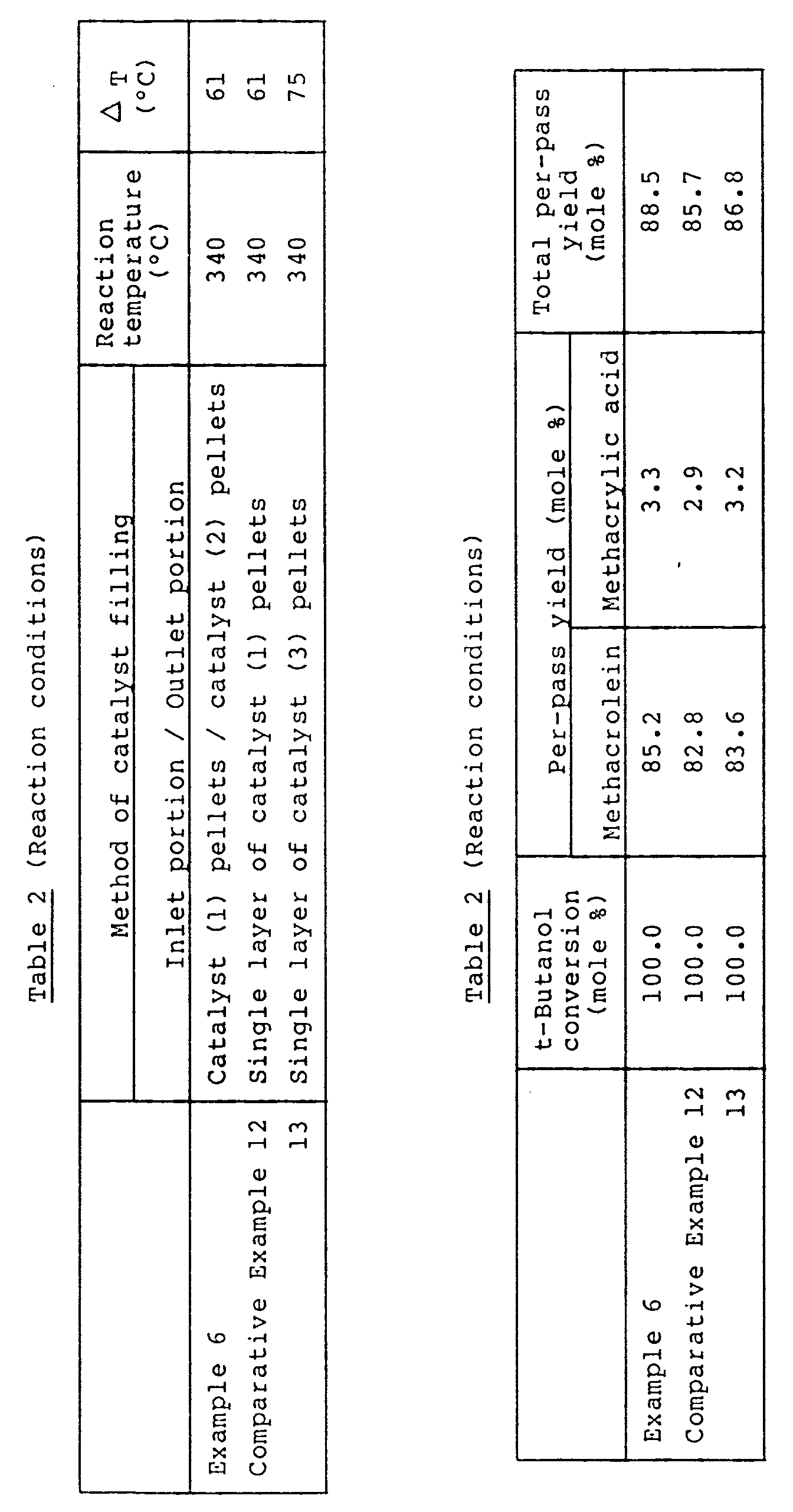


- 1,456 g of cobalt nitrate and 202 g of ferric nitrate were dissolved in 1,000 ml of water. 243 g of bismuth nitrate was dissolved in an aqueous nitric acid solution consisting of 30 ml of concentrated nitric acid and 120 ml of water.
- Separately, 1,059 g of ammonium paramolybdate and 265 g of ammonium paratungstate were dissolved in 3,000 ml of water being stirred with heating. To the resulting aqueous solution were dropwise added the above prepared two aqueous solutions, and mixing was carried out. Thereto were added an aqueous solution obtained by dissolving 68.3 g of cesium nitrate in 200 ml of water, and 203 g of silica sol of 20 weight % concentration in this order, and mixing was carried out.
- The thus obtained suspension was stirred with heating, and subjected to evaporation to dryness. The residue was molded into pellets of 6 mm in outside diameter and 6.6 mm in length. The pellets were fired at 510°C for 6 hours in an air stream to obtain a catalyst (1-a). This catalyst (1-a) had the following composition in terms of atomic ratio excluding oxygen.
Mo₁₂W₂Bi₁Fe₁Co₁₀Cs0.7Si1.35
A catalyst (2-a) was prepared in the same manner as in the preparation of the catalyst (1-a) except that the amount of cesium nitrate was changed to 9.8 g and the firing temperature was changed to 480°C. - This catalyst (2-a) had the following composition in terms of atomic ratio excluding oxygen.
Mo₁₂W₂Bi₁Fe₁Co₁₀Cs0.1Si1.35
With respect to the activities of the catalysts (1-a) and (2-a), the catalyst (2-a) has a higher activity than the catalyst (1-a), as is clear from the results of Comparative Examples 1-a and 2-a shown later. - 750 ml of the catalyst (1-a) was filled into the material gas inlet portion of a steel-made reaction tube of 25.4 mm in diameter, and 750 ml of the catalyst (2-a) was filled into the material gas outlet portion.
- A mixed gas of a composition consisting of 6 % by volume of isobutylene, 13.2 % by volume of oxygen, 10 % by volume of steam and 70.8 % by volume of nitrogen was introduced from the inlet of the reaction tube, and a reaction was carried out at a reaction temperature of 340°C at a space velocity (SV) of 1,600 hr⁻¹ (STP). The results are shown in Table 1-a.
- A reaction was carried out in the same manner as in Example 1-a except that no catalyst (2-a) was used and only the catalyst (1-a) (1,500 ml) was filled. The results are shown in Table 1-a.
- A reaction was carried out in the same manner as in Example 1-a except that no catalyst (1-a) was used and only the catalyst (2-a) (1,500 ml) was filled. The results are shown in Table 1-a.
- A catalyst (3-a) was prepared in the same manner as for the catalyst (1-a) of Example 1-a except that the amount of cesium nitrate was changed to 39 g.
- This catalyst (3-a) had the following composition in terms of atomic ratio excluding oxygen.
Mo₁₂W₂Bi₁Fe₁Co₁₀Cs0.4Si1.35
A reaction was carried out in the same manner as in Example 1-a except that only the catalyst (3-a) (1,500 ml) was filled into the reaction tube. The results are shown in Table 1-a. - A catalyst (4-a) and a catalyst (5-a) were prepared in the same manners as for the catalyst (1-a) and the catalyst (2-a), respectively, except that the firing temperatures used in the preparations of the catalyst (1-a) and the catalyst (2-a) were both changed to 500°C. 750 ml of the catalyst (4-a) was filled into the reaction gas inlet portion, and 750 ml of the catalyst (5-a) was filled into the outlet portion. Then, a reaction was carried out in the same manner as in Example 1-a. The results are shown in Table 1-a.
- It is appreciated from the results of Example 1-a and Comparative Examples 1-a to 3-a that the catalyst (1-a) has a very low activity, the catalyst (2-a) has a high activity, and both of them give a low total per-pass yield while the catalyst system of the present invention which is a combination of the catalysts (1-a) and (2-a), gives high total per-pass yield and produces intended methacrolein and methacrylic acid at high yields.
- When the catalyst (3-a) having a composition intermediate between those of the catalysts (1-a) and (2-a) is compared with the catalyst system of the present invention which is a combination of the catalysts (1-a) and (2-a), the catalyst (3-a) gives a low total per-pass yield and a very large temperature difference (a very large ΔT) between the reaction temperature and the hot spots temperature. Therefore, it is thought that catalyst deterioration due to thermal load is striking in the catalyst (3-a). Accordingly, it is appreciated that the single use of the catalyst (3-a) having substantially the same composition as the present catalyst system in unable to achieve the effect of the present invention.
- Further, it is clear that Comparative Example 4-a is superior to Comparative Examples 1-a to 3-a in yield and ΔT but, inferior to Example 1-a using the catalysts of the present invention in said properties. Thus, it is appreciated that the variation of the firing temperature in addition to the variation of the B group elements gives a further improved element.
- A reaction was carried out in the same manner as in Example 1-a except that the catalysts (1-a) and (2-a) were both molded into rings of 6 mm in outside diameter, 6.6 mm in length and 1 mm in inside diameter of through-hole. The results are shown in Table 1-a.
- A reaction was carried out in the same manner as in Comparative Example 1-a except that the catalyst (1-a) was molded into rings of 6 mm in outside diameter, 6.6 mm in length and 1 mm in inside diameter of through-hole. The results are shown in Table 1-a.
- A reaction was carried out in the same manner as in Comparative Example 2-a except that the catalyst (2-a) was molded into rings of 6 mm in outside diameter, 6.6 mm in length and 1 mm in inside diameter of through-hole. The results are shown in Table 1-a.
- A reaction was carried out in the same manner as in Comparative Example 3-a except that the catalyst (3-a) was molded into rings of 6 mm in outside diameter, 6.6 mm in length and 1 mm in inside diameter of through-hole. The results are shown in Table 1-a.
- A reaction was carried out in the same manner as in Comparative Example 4-a except that the catalysts (4-a) and (5-a) were both molded into rings of 6 mm in outside diameter, 6.6 mm in length and 1 mm in inside diameter of through-hole. The results are shown in Table 1-a.
- In Examples 2-a and Comparative Examples 5-a to 8-a, the shapes of the catalysts (1-a) to (5-a) were changed from pellets to rings. It is appreciated from the results of Table 1-a that the variation of the catalyst shape into rings gives an improvement in yield and a reduction in ΔT in each case of the catalysts (1-a) to (3-a) and the combined use of the catalysts (4-a) and (5-a), but the catalyst system of the present invention using the catalysts (1-a) and (2-a) in combination gives an even better yield and an even better ΔT.
- A reaction was carried out in the same manner as in Example 1-a except that the reaction was carried out for a longer period up to 4,000 hours. The results are shown in Table 1-a.
- It is appreciated from the results of Table 1-a that even after the reaction of 4,000 hours, the reduction in catalyst activity is very low and the reduction in yield is substantially negligible and that the catalyst system of the present invention enables very stable continuous operation over a long period of time.
- A reaction was carried out in the same manner as in Comparative Example 3-a except that the reaction was carried out for a longer period up to 4,000 hours. The results are shown in Table 1-a.
- In each case of Example 3-a and Comparative Example 9-a, the reductions in catalyst activity and yield after 4,000 hours are very small, and there is no large difference in catalyst stability between Example 3-a and Comparative Example 9-a. It is clear therefore that the superiority in yield, of Example 1-a of the present invention over Comparative Example 4-a appears even after 4,000 hours.
- A reaction was carried out in the same manner as in Example 2-a except that the reaction temperature was changed to 360°C and the space velocity was changed to 3,000 hour⁻¹ (STP). The results are shown in Table 1-a.
- A reaction was carried out in the same manner as in Comparative Example 4-a except that the reaction temperature was changed to 360°C and the space velocity was changed to 3,000 hour⁻¹ (STP). The results are shown in Table 1-a.
- It is appreciated from the results of Example 4-a and Comparative Example 10-a that the superiority in activity and yield, of the catalyst system of the present invention using the catalysts (1-a) and (2-a) in combination, over the catalyst system using the catalysts (4-a) and (5-a) in combination appears even when the space velocity is increased.
- A reaction was effected in the same manner as in Example 2-a except that the proportions of isobutylene and nitrogen in material gas were changed to 7 % by volume and 69.8 % by volume, respectively. The results are shown in Table 1-a.
- A reaction was effected in the same manner as in Comparative Example 4-a except that the proportions of isobutylene and nitrogen in material gas were changed to 7 % by volume and 69.8 % by volume, respectively. The results are shown in Table 1-a.
- It is appreciated from the results of Example 5-a and Comparative Example 11-a that the superiority in yield and ΔT, of the catalyst system of the present invention using the catalysts (1-a) and (2-a) in combination, over the catalyst system using the catalysts (4-a) and (5-a) in combination appears even when the isobutylene concentration is incerased.
- A reaction was carried out in the same manner as in Example 1-a except that t-butanol was used in place of isobutylene. The results are shown in Table 2-a.
- A reaction was carried out in the same manner as in Comparative Example 4-a except that t-butanol was used in place of isobutylene. The results are shown in Table 2-a.
- A reaction was carried out in the same manner as in Example 2-a except that there was used, as the material gas, a mixed gas consisting of 5 % by volume of methyl t-butyl ether (MTBE), 13.2 % by volume of oxygen, 10 % by volume of steam and 71.8 % by volume of nitrogen, the reaction temperature was changed to 360°C and the space velocity was changed to 1,000 hr⁻¹ (STP). The results are shown in Table 3-a.
- A reaction was carried out in the same manner as in Comparative Example 4-a except that there was used, as the material gas, a mixed gas consisting of 5 % by volume of methyl t-butyl ether (MTBE), 13.2 % by volume of oxygen, 10 % by volume of steam and 71.8 % by volume of nitrogen, the reaction temperature was changed to 360°C and the space velocity was changed to 1,000 hr⁻¹ (STP). The results are shown in Table 3-a.
- A catalyst (6-a) was prepared in the same manner as in Example 1-a except that nickel nitrate was used in place of cobalt nitrate, phosphoric acid was added after ammonium paratungstate, rubidium nitrate was used in place of cesium nitrate, stannic oxide was added after rubidium nitrate, aluminum nitrate was used in place of silica sol, and the firing temperature was changed to 520°C.
- This catalyst (6-a) had the following composition in terms of atomic ratio excluding oxygen.
Mo₁₂W₂Bi₃Fe₁Ni₇Rb₁P0.2Sn0.5Al₁
A catalyst (7-a) was prepared in the same manner as for the catalyst (6-a) except that the amount of rubidium nitrate used was changed and the firing temperature was changed to 490°C. - This catalyst (7-a) had the following composition in terms of atomic ratio excluding oxygen.
Mo₁₂W₂Bi₃Fe₁Ni₇Rb0.2P0.2Sn0.5Al₁
750 ml of the catalyst (6-a) was filled into the gas inlet portion of a steel-made reaction tube of 25.4 mm in diameter, and 750 ml of the catalyst (7-a) was filled into the gas outlet portion. - A reaction was carried out in the same manner as in Example 1-a. The results are shown in Table 4-a.
- A catalyst (8-a) and a catalyst (9-a) were prepared in the same manner as for the catalyst (6-a) and the catalyst (7-a), respectively, except that the firing temperature was changed to 500°C in each preparation. 750 ml of the catalyst (8-a) was filled into the reaction gas inlet portion, and 750 ml of the catalyst (9-a) was filled into the reaction gas outlet portion. A reaction was carried out in the same manner as in Example 8-a. The results are shown in Table 4-a.
- A catalyst (10-a) was obtained in the same manner as in Example 1-a except that no ammonium paratungstate was used, cerium nitrate was replaced by potassium nitrate, lithium nitrate, magnesium nitrate and calcium nitrate, titanium dioxide was used in place of silica sol, finally there were used cerous nitrate and niobium pentoxide, and the firing temperature was changed to 520°C.
- This catalyst (10-a) had the following composition in terms of atomic ratio excluding oxygen.
Mo₁₂Bi₁Fe₁Co₁₀K1.2Li0.5Ca0.2Mg0.2Nb0.5Ce₁Ti₁
A catalyst (11-a) was prepared in the same manner as for the catalyst (10-a) except that the amounts of potassium nitrate and lithium nitrate used were changed and the firing temperature was changed to 480°C. - This catalyst (11-a) has the following composition in terms of atomic ratio excluding oxygen.
Mo₁₂Bi₁Fe₁CO₁₀K0.5Li0.2Ca0.2Mg0.2Nb0.5Ce₁Ti₁
750 ml of the catalyst (10-a) was filled into the gas inlet portion of a steel-made reaction tube of 25.4 mm in diameter, and 750 ml of the catalyst (11-a) was filled into the gas outlet portion. - A reaction was carried out in the same manner as in Example 1-a. The results are shown in Table 4-a.
- A catalyst (12-a) and a catalyst (13-a) were prepared in the same manners as for the catalyst (10-a) and the catalyst (11-a), respectively, except that the firing temperature was 500°C in each preparation. 750 ml of the catalyst (12-a) was filled into the reaction gas inlet portion, and 750 ml of the catalyst (13-a) was filled into the reaction gas outlet portion. A reaction was carried out in the same manner as in Example 9-a. The results are shown in Table 4-a.
- A suspension was prepared in the same manner as in Example 1-a except that no ammonium paratungstate was used, thallous nitrate and strontium nitrate were used in place of cesium nitrate, thereafter there were added tellurium oxide, lead nitrate and zinc nitrate, silica sol replaced by titanium dioxide, and the firing temperature was changed to 530°C.
- The suspension was stirred with heating and subjected evaporation to dryness. The residue was molded into rings of 6 mm in outside diameter, 6.6 mm in length and 2 mm in inside diameter of through-hole, and fired at 500°C for 6 hours in an air stream to obtain a catalyst (14-a).
- The catalyst (14-a) had the following composition in terms of atomic ratio excluding oxygen.
Mo₁₂Bi₁Fe₃Co₇Tl0.7Sr0.3Te0.3Pb₁Zn0.5Ti₁
A catalyst (15-a) was prepared in the same manner as for the catalyst (14-a) except that the amount of thallous nitrate was changed and the firing temperature was changed to 480°C. - The catalyst (15-a) had the following composition in terms of atomic ratio excluding oxygen.
Mo₁₂Bi₁Fe₃Co₇Tl0.05Sr0.3Te0.3Pb₁Zn0.5Ti₁
750 ml of the catalyst (14-a) was filled into the gas inlet portion of a steel-made reactor of 25.4 mm in diameter, and 750 ml of the catalyst (15-a) was filled into the gas outlet portion. - A reaction was carried out in the same manner as in Example 1-a. The results are shown in Table 4-a.
- A catalyst (16-a) and a catalyst (17-a) were prepared in the same manners as for the catalyst (14-a) and the catalyst (15-a), respectively, except that the firing temperatures used in Example 10-a for the preparation of the catalyst (14-a) and the catalyst (15-a) were changed to 500°C. 750 ml of the catalyst (16-a) was filled into the reaction gas inlet portion, and 750 ml of the catalyst (17-a) was filled into the reaction gas outlet portion. A reaction was carried out in the same manner as in Example 10-a. The results are shown in Table 4-a.
- A suspension was prepared in the same manner as in Example 1-a except that cesium nitrate was replaced by potassium nitrate, barium nitrate and beryllium nitrate, then antimony trioxide and manganese nitrate were added, silica sol was replaced by zirconium nitrate, and the firing temperature was changed to 530°C.
- Using this suspension, the procedure of Example 10-a was repeated to prepare a catalyst (18-a).
- The catalyst (18-a) had the following composition in terms of atomic ratio excluding oxygen.
Mo₁₂W1.5Bi₁Fe1.2Co₅K1.8Ba0.2Be0.2Sb₁Mn0.5Zr₁
A catalyst (19-a) was obtained in the same manner as for the catalyst (18-a) except that potassium nitrate was replaced by sodium nitrate and the firing temperature was changed to 470°C. - The catalyst (19-a) had the following composition in terms of atomic ratio excluding oxygen.
Mo₁₂W1.5Bi₁Fe1.2Co0.5Na1.0Ba0.2Be0.2Sb₁Mn0.5Zr₁
750 ml of the catalyst (18-a) was filled into the gas inlet portion of a steel-made reaction tube of 25.4 mm in diameter, and 750 ml of the catalyst (19-a) was filled into the gas outlet portion. - A reaction was carried out in the same manner as in Example 1-a. The results are shown in Table 4-a.
- A catalyst (20-a) and a catalyst (21-a) were prepared in the same manners as for the catalyst (18-a) and the catalyst (19-a), respectively, except that the firing temperatures used in Example 11-a for the preparation of the catalyst (18-a) and the catalyst (19-a) were changed to 500°C. 750 ml of the catalyst (20-a) was filled into the reaction gas inlet portion, and 750 ml of the catalyst (21-a) was filled into the gas outlet portion. A reaction was carried out in the same manner as in Example 11-a. The results are shown in Table 4-a.


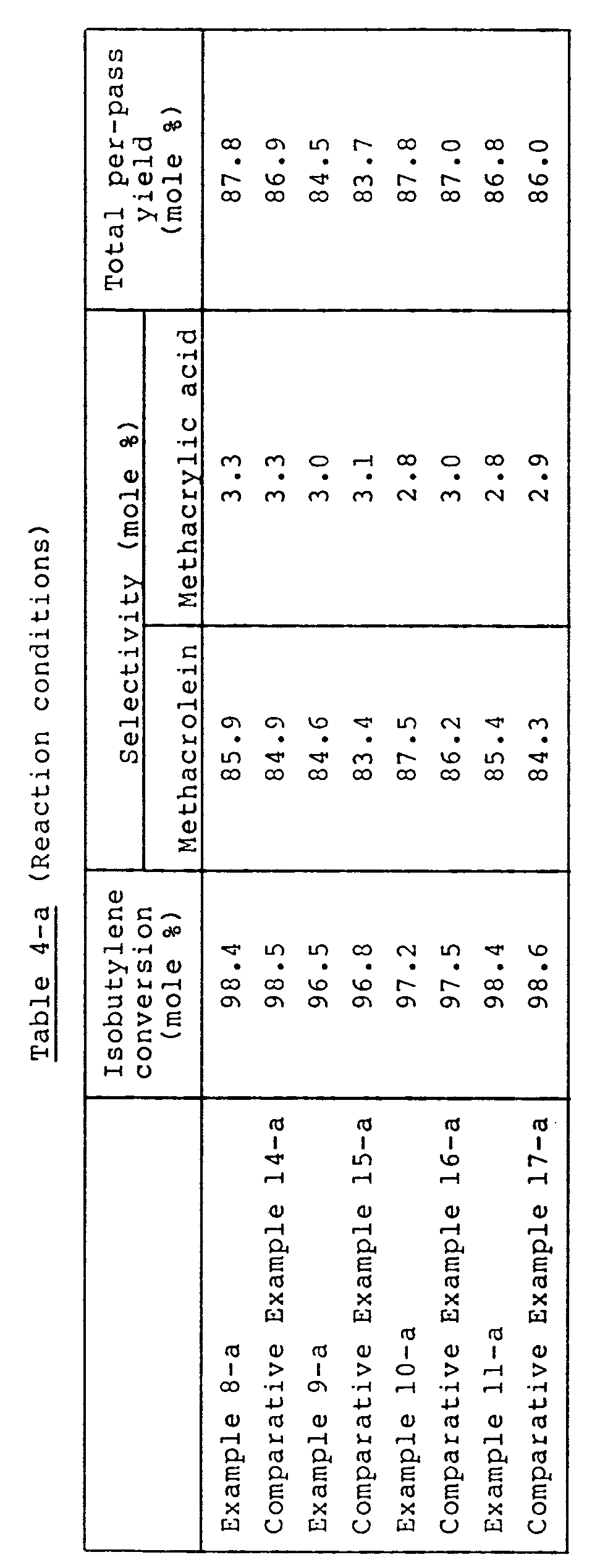
- 1,456 g of cobalt nitrate and 202 g of ferric nitrate were dissolved in 1,000 ml of water. 243 g of bismuth nitrate was dissolved in an aqueous nitric acid solution consisting of 30 ml of concentrated nitric acid and 120 ml of water.
- Separately, 1,059 g of ammonium paramolybdate and 265 g of ammonium paratungstate were dissolved in 3,000 ml of water being stirred with heating. To the resulting aqueous solution were dropwise added the above prepared two aqueous solutions, and mixing was carried out. Thereto were added an aqueous solution obtained by dissolving 68.3 g of cesium nitrate and 13.1 g of barium nitrate in 400 ml of water, and 203 g of silica sol of 20 weight % concentration in this order, and mixing was carried out.
- The thus obtained suspension was stirred with heating, and subjected to evaporation to dryness. The residue was molded into pellets of 6 mm in outside diameter and 6.6 mm in length. The pellets were fired at 500°C for 6 hours in an air stream to obtain a catalyst (1-b). This catalyst (1-b) had the following composition in terms of atomic ratio excluding oxygen.
Mo₁₂W₂Bi₁Fe₁Co₁₀Cs0.7Ba0.1Si1.35
A catalyst (2-b) was prepared in the same manner as in the preparation of the catalyst (1-b) except that the amount of barium nitrate was changed to 65.3 g. This catalyst (2-b) had the following composition in terms of atomic ratio excluding oxygen.
Mo₁₂W₂Bi₁Fe₁Co₁₀Cs0.7Ba0.6Si1.35
With respect to the activities of the catalysts (1-b) and (2-b), the catalyst (2-b) has a higher activity than the catalyst (1-b), as is clear from the results of Comparative Examples 1-b and 2-b shown later. - 750 ml of the catalyst (1-b) was filled into the material gas inlet portion of a steel-made reaction tube of 25.4 mm in diameter, and 750 ml of the catalyst (2-b) was filled into the material gas outlet portion.
- A mixed gas of a composition consisting of 6 % by volume of isobutylene, 13.2 % by volume of oxygen, 10 % by volume of steam and 70.8 % by volume of nitrogen was introduced from the inlet of the reaction tube, and a reaction was carried out at a reaction temperature of 340°C at a space velocity (SV) of 1,600 hr⁻¹ (STP). The results are shown in Table 1-b.
- A reaction was carried out in the same manner as in Example 1-b except that no catalyst (2-b) was used and only the catalyst (1-b) (1,500 ml) was filled. The results are shown in Table 1-b.
- A reaction was carried out in the same manner as in Example 1-b except that no catalyst (1-b) was used and only the catalyst (2-b) (1,500 ml) was filled. The results are shown in Table 1-b.
- A catalyst (3-b) was prepared in the same manner as for the catalyst (1-b) of Example 1-b except that the amount of barium nitrate was changed to 39.2 g. This catalyst (3-b) had the following composition in terms of atomic ratio excluding oxygen.
Mo₁₂W₂Bi₁Fe₁Co₁₀Cs0.7Ba0.35Si1.35
A reaction was carried out in the same manner as in Example 1-b except that only the catalyst (3-b) (1,500 ml) was filled into the reaction tube. The results are shown in Table 1-b. - It is appreciated from the results of Table 1-b that the catalyst (1-b) has a very low activity, the catalyst (2-b) has a high activity but a low selectivity, and both of them give a low total per-pass yield while the catalyst system of the present invention which is a combination of the catalysts (1-b) and (2-b), gives a high total per-pass yield and produces intended methacrolein and methacrylic acid at high yields.
- When the catalyst (3-b) having a composition intermediate between those of the catalysts (1-b) and (2-b) is compared with the catalyst system of the present invention which is a combination of the catalysts (1-b) and (2-b), the catalyst (3-b) gives a low total per-pass yield and a very large temperature difference ( a very large ΔT) between the reaction temperature and the highest temperature in catalyst layer. Therefore, it is thought that catalyst deterioration due to thermal load is striking in the catalyst (3-b). Accordingly, it is appreciated that the single use of the catalyst (3-b) having substantially the same composition as the present catalyst system is unable to achieve the effect of the present invention.
- A reaction was carried out in the same manner as in Example 1-b except that the catalysts (1-b) and (2-b) were both molded into rings of 6 mm in outside diameter, 6.6 mm in length and 1 mm in inside diameter of through-hole. The results are shown in Table 1-b.
- A reaction was carried out in the same manner as in Comparative Example 1-b except that the catalyst (1-b) was molded into rings of 6 mm in outside diameter, 6.6 mm in length and 1 mm in inside diameter of through-hole. The results are shown in Table 1-b.
- A reaction was carried out in the same manner as in Comparative Example 2-b except that the catalyst (2-b) was molded into rings of 6 mm in outside diameter, 6.6 mm in length and 1 mm in inside diameter of through-hole. The results are shown in Table 1-b.
- A reaction was carried out in the same manner as in Comparative Example 3-b except that the catalyst (3-b) was molded into rings of 6 mm in outside diameter, 6.6 mm in length and 1 mm in inside diameter of through-hole. The results are shown in Table 1-b.
- In Example 2-b and Comparative Examples 4-b to 6-b, the shapes of the catalysts (1-b) to (3-b) were changed from pellets to rings. It is appreciated from the results of Table 1-b that the change of catalyst shape to rings gives improvement in yield and reduction in ΔT in all of the catalysts (1-b) to (3-b), but the catalyst system of the present invention using the catalysts (1-b) and (2-b) in combination gives a higher yield and a lower ΔT than the single use of the catalyst (1-b), (2-b) or (3-b).
- A reaction was carried out in the same manner as in Example 1-b except that the reaction was carried out for an extended period of time up to 4,000 hours. The results are shown in Table 1-b.
- It is appreciated from the results of Table 1-b that activity reduction is very low even after the reaction of 4,000 hours, yield reduction is substantially negligible, and the catalyst system of the present invention enables very stable operation over a long period of time.
- A reaction was carried out in the same manner as in Comparative Example 3-b except that the reaction time was changed to 4,000 hours. The results are shown in Table 1-b.
- It is appreciated from the results of Table 1-b that in Comparative Example 7-b, as compared with Example 3-b, activity reduction and yield reduction are both large and the catalyst has a problem in stability.
- A reaction was carried out in the same manner as in Example 2-b except that the reaction temperature was changed to 360°C and the space velocity was changed to 3,000 hr⁻¹ (STP). The results are shown in Table 1-b.
- A reaction was carried out in the same manner as in Comparative Example 4-b except that the reaction temperature was changed to 360°C and the space velocity was changed to 3,000 hr⁻¹ (STP). The results are shown in Table 1-b.
- A reaction was carried out in the same manner as in Comparative Example 6-b except that the reaction temperature was changed to 360°C and the space velocity was changed to 3,000 hr⁻¹ (STP). The results are shown in Table 1-b.
- It is appreciated from the results of Example 4-b and Comparative Examples 8-b and 9-b that the superiority in activity and yield, of the catalyst system of the present invention using the catalysts (1-b) and (2-b) in combination, over the catalyst (1-b) or (3-b) appears even when space velocity is increased.
- A reaction was carried out in the same manner as in Example 2-b except that the proportions of isobutylene and nitrogen in material gas were changed to 7 % by volume and 69.8 % by volume, respectively. The results are shown in Table 1-b.
- A reaction was carried out in the same manner as in Example 4-b except that the proportions of isobutylene and nitrogen in material gas were changed to 7 % by volume and 69.8 % by volume, respectively. The results are shown in Table 1-b.
- A reaction was carried out in the same manner as in Example 6-b except that the proportions of isobutylene and nitrogen in material gas were changed to 7 % by volume and 69.8 % by volume, respectively. The results are shown in Table 1-b.
- It is appreciated from the results of Example 5-b and Comparative Examples 10-b and 11-b that the superiority in yield and ΔT, of the catalyst system of the present invention using the catalysts (1-b) and (2-b) in combination, over the catalyst (1-b) or (3-b) appears even when isobutylene concentration is increased. The present catalyst system, as compared with the single use of the catalyst (1-b) or (3-b), gives a considerably small increase in ΔT of catalyst layer, in particular. Therefore, it is thought that catalyst arrangement as in the present invention is effective for minimization of catalyst deterioration caused by thermal load.
- A reaction was carried out in the same manner as in Example 1-b except that isobutylene was replaced by t-butanol. The results are shown in Table 2-b.
- A reaction was carried out in the same manner as in Comparative Example 1-b except that isobutylene was replaced by t-butanol. The results are shown in Table 2-b.
- A reaction was carried out in the same manner as in Comparative Example 3-b except that isobutylene was replaced by t-butanol. The results are shown in Table 2-b.
- A reaction was carried out in the same manner as in Example 2-b except that there was used a material gas consisting of 5 % by volume of methyl t-butyl ether (MTBE), 13.2 % by volume of oxygen, 10 % by volume of steam and 71.8 % by volume of nitrogen, the reaction temperature was changed to 360°C and the space velocity was changed to 1,000 hr⁻¹ (STP). The results are shown in Table 3-b.
- A reaction was carried out in the same manner as in Comparative Example 4-b except that there was used a material gas consisting of 5 % by volume of MTBE, 13.2 % by volume of oxygen, 10 % by volume of steam and 71.8 % by volume of nitrogen, the reaction temperature was changed to 360°C and the space velocity was changed to 1,000 hr⁻¹ (STP). The results are shown in Table 3-b.
- A reaction was carried out in the same manner as in Comparative Example 6-b except that there was used a material gas consisting of 5 % by volume of MTBE, 13.2 % by volume of oxygen, 10 % by volume of steam and 71.8 % by volume of nitrogen, the reaction temperature was changed to 360°C and the space velocity was changed to 1,000 hr⁻¹ (STP). The results are shown in Table 3-b.
- A catalyst (4-b) was prepared in the same manner as in Example 1-b except that cobalt nitrate was replaced by nickel nitrate, phosphoric acid was added after ammonium paratungstate, there were used thallous nitrate and strontium nitrate in place of cesium nitrate and barium nitrate, then stannic oxide was added, and silica sol was replaced by ammonium nitrate.
- The catalyst (4-b) had the following composition in terms of atomic ratio excluding oxygen.
Mo₁₂W₂Bi₃Fe₁Ni₇T10.6Sr0.1P0.2Sn0.5Al₁
A catalyst (5-b) was prepared in the same manner as for the catalyst (4-b) except that the amount of strontium nitrate used was changed. - The catalyst (5-b) had the following composition in terms of atomic ratio excluding oxygen.
Mo₁₂W₂Bi₃Fe₁Ni₇Tl0.6Sr0.5P0.2Sn0.5Al₁
750 ml of the catalyst (4-b) was filled into the gas inlet side of a steel-made reaction tube of 25.4 mm in diameter, and 750 ml of the catalyst (5-b) was filled into the gas outlet side. - A reaction was carried out in the same manner as in Example 1-b. The results are shown in Table 4-b.
- A reaction was carried out in the same manner as in Example 8-b except that no catalyst (5-b) was used and only the catalyst (4-b) (1,500 ml) was filled. The results are shown in Table 4-b.
- A reaction was carried out in the same manner as in Example 8-b except that no catalyst (4-b) was used and only the catalyst (5-b) (1,500 ml) was filled. The results are shown in Table 4-b.
- A catalyst (6-b) was obtained in the same manner as in Example 1-b except that no ammonium paratungstate was used, cesium nitrate was replaced by potassium nitrate and sodium nitrate, barium nitrate was replaced by calcium nitrate and beryllium nitrate, silica sol was replaced by titanium dioxide, and cerous nitrate and niobium pentoxide were used finally. The catalyst (6-b) had the following composition in terms of atomic ratio excluding oxygen.
Mo₁₂Bi₁Fe₁Co₆K0.8Na0.2Ca0.1Be0.1Nb0.5Ce₁Ti₁
A catalyst (7-b) was prepared in the same manner as for the catalyst (6-b) except that the amounts of calcium nitrate and beryllium nitrate were changed. The catalyst (7-b) had the following composition in terms of atomic ratio excluding oxygen.
Mo₁₂Bi₁Fe₁Co₆K0.8Na0.2Ca0.7Be0.3Nb0.5Ce₁Ti₁
750 ml of the catalyst (6-b) was filled into the gas inlet portion of a steel-made reaction tube of 25.4 mm in diameter, and 750 ml of the catalyst (7-b) was filled into the gas outlet portion. - A reaction was carried out in the same manner as in Example 1-b. The results are shown in Table 4-b.
- A reaction was carried out in the same manner as in Example 9-b except that no catalyst (7-b) was used and only the catalyst (6-b) (1,500 ml) was filled. The results are shown in Table 4-b.
- A reaction was carried out in the same manner as in Example 9-b except that no catalyst (6-b) was used and only the catalyst (7-b) (1,500 ml) was filled. The results are shown in Table 4-b.
- A suspension was prepared in the same manner as in Example 1-b except that no ammonium paratungstate was used, cesium nitrate was replaced by rubidium nitrate, magnesium nitrate was used together with barium nitrate, then there were added tellurium dioxide, lead nitrate and zinc nitrate, and silica sol was replaced by titanium dioxide.
- The suspension was stirred with heating and subjected to evaporation to dryness. The residue was molded into rings of 6 mm in outside diameter, 6.6 mm in length and 2 mm in inside diameter of through-hole, and fired at 500°C for 6 hours in an air stream to obtain a catalyst (8-b). The catalyst (8-b) had the following composition in terms of atomic ratio excluding oxygen.
Mo₁₂Bi₁Fe₃Co₇Rb0.5Ba0.1Mg0.1Te0.3Pb₁Zn0.5Ti₁
A catalyst (9-b) was obtained in the same manner as for the catalyst (8-b) except that the amounts of barium nitrate and magnesium nitrate were changed. The catalyst had the following composition in terms of atomic ratio excluding oxygen.
Mo₁₂Bi₁Fe₃Co₇Rb0.5Ba0.2Mg1.0Te0.3Pb₁Zn0.5Ti₁
750 ml of the catalyst (8-b) was filled into the gas inlet side of a steel-made reactor of 25.4 mm in diameter, and 750 ml of the catalyst (9-b) was filled into the gas outlet side. A reaction was carried out in the same manner as in Example 1-b except that the reaction temperature was changed to 350°C. The results are shown in Table 4-b. - A reaction was carried out in the same manner as in Example 10-b except that no catalyst (9-b) was used and only the catalyst (8-b) (1,500 ml) was filled. The results are shown in Table 4-b.
- A reaction was carried out in the same manner as in Example 10-b except that no catalyst (8-b) was used and only the catalyst (9-b) (1,500 ml) was filled. The results are shown in Table 4-b.
- A suspension was prepared in the same manner as in Example 1-b except that lithium nitrate was used together with cesium nitrate, barium nitrate was replaced by calcium nitrate, then there were added antimony trioxide and manganese nitrate, and silica sol was replaced by zirconium nitrate.
- Using the suspension, a catalyst (10-b) was prepared in the same manner as in Example 10-b. The catalyst (10-b) had the following composition in terms of atomic ratio excluding oxygen.
Mo₁₂W1.5Bi₁Fe1.2Co₅Cs0.4Li0.1Ca0.2Sb₁Mn0.5Zr₁
A catalyst (11-b) was prepared in the same manner as for the catalyst (10-b) except that calcium nitrate was replaced by magnesium nitrate. The catalyst (11-b) had the following composition in terms of atomic ratio excluding oxygen.
Mo₁₂W1.5Bi₁Fe1.2Co₅Cs0.4Li0.1Mg0.8Sb₁Mn0.5Zr₁
750 ml of the catalyst (10-b) was filled into the gas inlet portion of a steel-made reaction tube of 25.4 mm in diameter, and 750 ml of the catalyst (11-b) was filled into the gas outlet side. - A reaction was carried out in the same manner as in Example 1-b. The results are shown in Table 4-b.
- A reaction was carried out in the same manner as in Example 11-b except that no catalyst (11-b) was used and only the catalyst (10-b) (1,500 ml) was filled. The results are shown in Table 4-b.
- A reaction was carried out in the same manner as in Example 11-b except that no catalyst (10-b) was used and only the catalyst (11-b) (1,500 ml) was filled. The results are shown in Table 4-b.
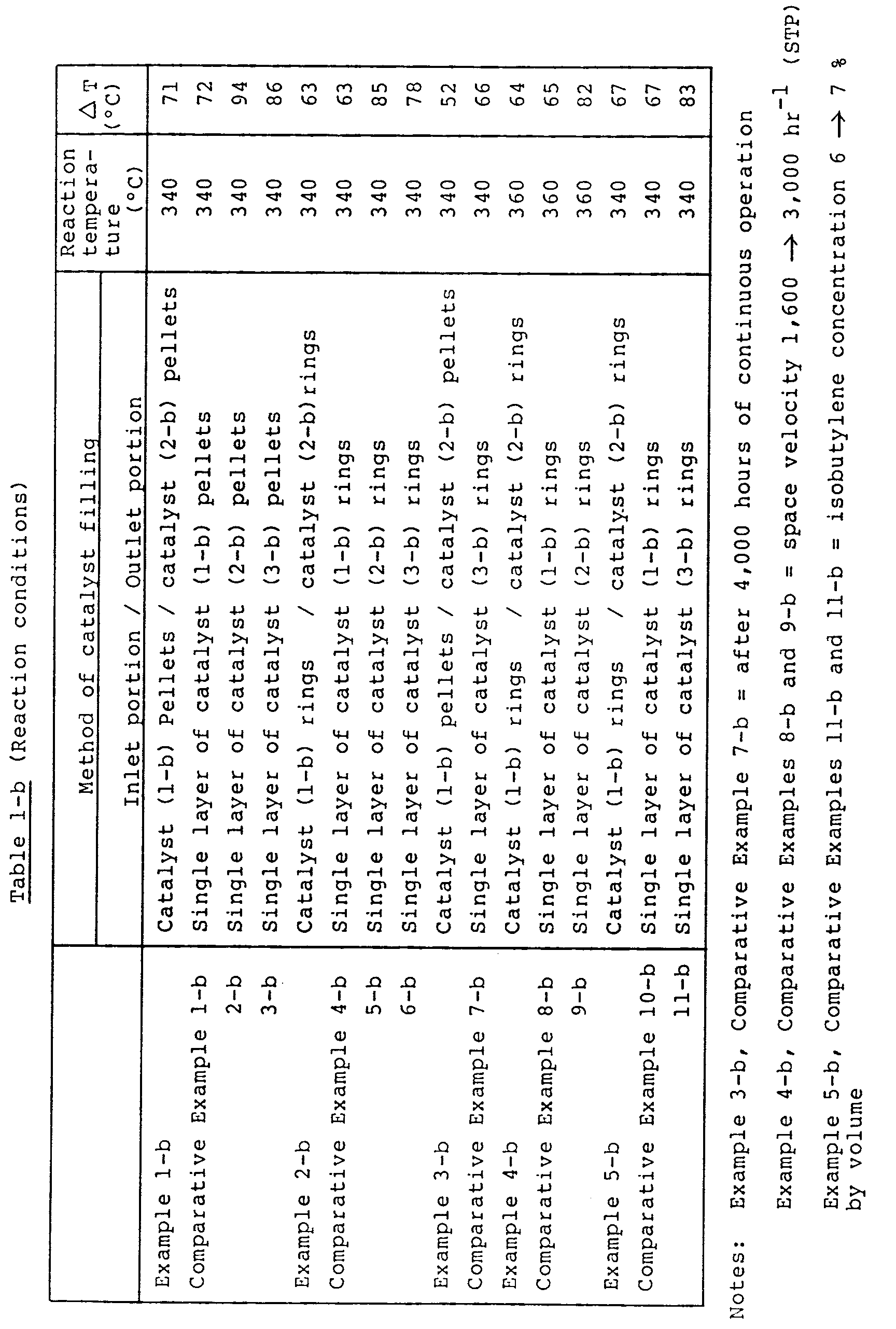


- 1,456 g of cobalt nitrate and 202 g of ferric nitrate were dissolved in 1,000 ml of water. 243 g of bismuth nitrate was dissolved in an aqueous nitric acid solution consisting of 30 ml of concentrated nitric acid and 120 ml of water.
- Separately, 1,059 g of ammonium paramolybdate and 265 g of ammonium paratungstate were dissolved in 3,000 ml of water being stirred with heating. To the resulting aqueous solution were dropwise added the above prepared two aqueous solutions, and mixing was carried out. Thereto were added an aqueous solution obtained by dissolving 9.8 g of cesium nitrate in 30 ml of water, 79.8 g of tellurium dioxide and 203 g of silica sol of 20 weight % concentration in this order, and mixing was carried out.
- The thus obtained suspension was stirred with heating, and subjected to evaporation to dryness. The residue was molded into pellets of 6 mm in outside diameter and 6.6 mm in length. The pellets were fired at 500°C for 6 hours in an air stream to obtain a catalyst (1-c). This catalyst (1-c) had the following composition in terms of atomic ratio excluding oxygen.
Mo₁₂W₂Bi₁Fe₁Co₁₀Cs0.1Te1.0Si1.35
A catalyst (2-c) was prepared in the same manner as in the preparation of the catalyst (1-c) except that the amount of tellurium dioxide was changed to 8.0 g. This catalyst (2-c) had the following composition in terms of atomic ratio excluding oxygen.
Mo₁₂W₂Bi₁Fe₁Co₁₀Cs0.1Te0.1Si1.35
With respect to the activities of the catalysts (1-c) and (2-c), the catalyst (2-c) has a higher activity than the catalyst (1-c), as is clear from the results of Comparative Examples 1-c and 2-c shown later. - 750 ml of the catalyst (1-c) was filled into the material gas inlet portion of a steel-made reaction tube of 25.4 mm in diameter, and 750 ml of the catalyst (2-c) was filled into the material gas outlet portion.
- A mixed gas of a composition consisting of 6 % by volume of isobutylene, 13.2 % by volume of oxygen, 10 % by volume of steam and 70.8 % by volume of nitrogen was introduced from the inlet of the reaction tube, and a reaction was carried out at a reaction temperature of 340°C at a space velocity (SV) of 1,600 hr⁻¹ (STP). The results are shown in Table 1-c.
- A reaction was carried out in the same manner as in Example 1-c except that no catalyst (2-c) was used and only the catalyst (1-c) (1,500 ml) was filled into the reaction tube. The results are shown in Table 1-c.
- A reaction was carried out in the same manner as in Example 1-c except that no catalyst (1-c) was used and only the catalyst (2-c) (1,500 ml) was filled into the reaction tube. The results are shown in Table 1-c.
- A catalyst (3-c) was prepared in the same manner as for the catalyst (1-c) except that the amount of tellurium dioxide used was changed to 43.9 g.
- The catalyst (3-c) had the following composition in terms of atomic ratio excluding oxygen.
Mo₁₂W₂Bi₁Fe₁Co₁₀Cs0.1Te0.55Si1.35
A reaction was carried out in the same manner as in Example 1-c except that only the catalyst (3-c) (1,500 ml) was filled into the reaction tube. The results are shown in Table 1-c. - It is appreciated from the results of Table 1-c that the catalyst (1-c) has a very low activity, the catalyst (2-c) has a high activity but a low selectivity, and both of them give a low total per-pass yield while the catalyst system of the present invention which is a combination of the catalysts (1-c) and (2-c), gives a high total per-pass yield and produces intended methacrolein and methacrylic acid at high yields.
- When the catalyst (3-c) having a composition intermediate between those of the catalysts (1-c) and (2-c) is compared with the catalyst system of the present invention which is a combination of the catalysts (1-c) and (2-c), the catalyst (3-c) gives a low total per-pass yield and a very large temperature difference (a very large ΔT) between the reaction temperature and the highest temperature in catalyst layer. Therefore, it is thought that catalyst deterioration due to thermal load is striking in the catalyst (3-c). Accordingly, it is appreciated that the single use of the catalyst (3-c) having substantially the same composition as the present catalyst system is unable to achieve the effect of the present invention. It can be said from these matters that the catalyst system of the present invention is very superior in both per-pass yield and thermal load.
- A reaction was carried out in the same manner as in Example 1-c except that both of the catalysts (1-c) and (2-c) were molded into rings of 6 mm in outside diameter, 6.6 mm in length and 1 mm in inside diameter of through-hole. The results are shown in Table 1-c.
- A reaction was carried out in the same manner as in Comparative Example 1-c except that the catalyst (1-c) was molded into rings of 6 mm in outside diameter, 6.6 mm in length and 1 mm in inside diameter of through-hole. The results are shown in Table 1-c.
- A reaction was carried out in the same manner as in Comparative Example 2-c except that the catalyst (2-c) was molded into rings of 6 mm in outside diameter, 6.6 mm in length and 1 mm in inside diameter of through-hole. The results are shown in Table 1-c.
- A reaction was carried out in the same manner as in Comparative Example 3-c except that the catalyst (3-c) was molded into rings of 6 mm in outside diameter, 6.6 mm in length and 1 mm in inside diameter of through-hole. The results are shown in Table 1-c.
- In Example 2-c and Comparative Examples 4-c to 6-c, the shapes of the catalysts (1-c) to (3-c) were changed from pellets to rings. It is appreciated from the results of Table 1-c that the change of catalyst shape to rings gives improvement in yield and reduction in ΔT in all of the catalysts (1-c) to (3-c), but the catalyst system of the present invention using the catalysts (1-c) and (2-c) in combination gives a higher yield and a lower ΔT than the single use of the catalyst (1-c), (2-c) or (3-c).
- A reaction was carried out in the same manner as in Example 1-c except that the catalyst (1-c) was molded into rings of 6.0 mm in outside diameter, 6.6 mm in length and 1.9 mm in inside diameter of through-hole. The results are shown in Table 1-c.
- It was found that the change of the catalyst filled into the inlet portion of the reaction tube, from pellet shape to ring shape gives further improvement in per-pass yield and reduction in ΔT and accordingly the combination of ring-shaped catalysts gives superior results than the combination of pellet-shaped catalysts.
- A reaction was carried out in the same manner as in Example 1-c except that the reaction was carried out for an extended period of time up to 4,000 hours. The results are shown in Table 1-c.
- It is appreciated from the results of Table 1-c that activity reduction is very low even after the reaction of 4,000 hours, yield reduction is substantially negligible, and the catalyst system of the present invention enables very stable operation over a long period of time.
- A reaction was carried out in the same manner as in Comparative Example 3-c except that the reaction time was changed to 4,000 hours. The results are shown in Table 1-c.
- It is appreciated from the results of Table 1-c that in Comparative Example 7-c, as compared with Example 4-c, activity reduction and yield reduction are both large and the catalyst has a problem in stability.
- A reaction was carried out in the same manner as in Example 2-c except that the reaction temperature was changed to 360°C and the space velocity was changed to 3,000 hr⁻¹ (STP). The results are shown in Table 1-c.
- A reaction was carried out in the same manner as in Comparative Example 4-c except that the reaction temperature was changed to 360°C and the space velocity was changed to 3,000 hr⁻¹ (STP). The results are shown in Table 1-c.
- A reaction was carried out in the same manner as in Comparative Example 6-c except that the reaction temperature was changed to 360°C and the space velocity was changed to 3,000 hr⁻¹ (STP). The results are shown in Table 1-c.
- It is appreciated from the results of Example 5-c and Comparative Examples 8-c and 9-c that the superiority in activity and yield, of the catalyst system of the present invention using the catalysts (1-c) and (2-c) in combination, over the catalyst (1-c) or (3-c) appears even when space velocity is increased.
- A reaction was carried out in the same manner as in Example 2-c except that the proportions of isobutylene and nitrogen in material gas were changed to 7 % by volume and 69.8 % by volume, respectively. The results are shown in Table 1-c.
- A reaction was carried out in the same manner as in Example 4-c except that the proportions of isobutylene and nitrogen in material gas were changed to 7 % by volume and 69.8 % by volume, respectively. The results are shown in Table 1-c.
- A reaction was carried out in the same manner as in Example 6-c except that the proportions of isobutylene and nitrogen in material gas were changed to 7 % by volume and 69.8 % by volume, respectively. The results are shown in Table 1-c.
- It is appreciated from the results of Example 6-c and Comparative Examples 10-c and 11-c that the superiority in yield and ΔT, of the catalyst system of the present invention using the catalysts (1-c) and (2-c) in combination, over the catalyst (1-c) or (3-c) appears even when isobutylene concentration is increased. The present catalyst system, as compared with the single use of the catalyst (1-c) or (3-c), gives a considerable small increase in ΔT of catalyst layer, in particular. Therefore, it is thought that catalyst arrangement as in the present invention is effective for minimization of catalyst deterioration caused by thermal load.
- A reaction was carried out in the same manner as in Example 2-c except that isobutylene was replaced by t-butanol. The results are shown in Table 2-c.
- A reaction was carried out in the same manner as in Comparative Example 4-c except that isobutylene was replaced by t-butanol. The results are shown in Table 2-c.
- A reaction was carried out in the same manner as in Comparative Example 6-c except that isobutylene was replaced by t-butanol. The results are shown in Table 2-c.
- A reaction was carried out in the same manner as in Example 2-c except that there was used a material gas consisting of 5 % by volume of methyl t-butyl ether (MTBE), 13.2 % by volume of oxygen, 10 % by volume of steam and 71.8 % by volume of nitrogen, the reaction temperature was changed to 360°C and the space velocity was changed to 1,000 hr⁻¹ (STP). The results are shown in Table 3-c.
- A reaction was carried out in the same manner as in Comparative Example 4-c except that there was used a material gas consisting of 5 % by volume of MTBE, 13.2 % by volume of oxygen, 10 % by volume of steam and 71.8 % by volume of nitrogen, the reaction temperature was changed to 360°C and the space velocity was changed to 1,000 hr⁻¹ (STP). The results are shown in Table 3-c.
- A reaction was carried out in the same manner as in Comparative Example 6-c except that there was used a material gas consisting of 5 % by volume of MTBE, 13.2 % by volume of oxygen, 10 % by volume of steam and 71.8 % by volume of nitrogen, the reaction temperature was changed to 360°C and the space velocity was changed to 1,000 hr⁻¹ (STP). The results are shown in Table 3-c.
- A suspension was prepared in the same manner as in Example 1-c except that cobalt nitrate was replaced by nickel nitrate, the amount of bismuth nitrate used was changed, cesium nitrate was replaced by rubidium nitrate and magnesium nitrate, then stannic oxide was added in place of tellurium dioxide, and aluminum nitrate was used in addition to silica sol. The suspension was subjected to the same procedure as in Example 2-c to prepare a ring-shaped catalyst (4-c).
- The catalyst (4-c) had the following composition in terms of atomic ratio excluding oxygen.
Mo₁₂W₂Bi1.2Fe₁Ni₇Rb0.1Mg0.5Sn1.0Al1.0Si1.35
A suspension was prepared in the same manner as for the catalyst (4-c) except that the amounts of stannic oxide and silica sol used were changed. The suspension was subjected to the same procedure as in Example 1-c to prepare a pellet-shaped catalyst (5-c). - The catalyst (5-c) had the following composition in terms of atomic ratio excluding oxygen.
Mo₁₂W₂Bi2.0Fe₁Ni₇Rb0.1Mg0.5Sn0.1Al1.0Si0.5
750 ml of the catalyst (4-c) was filled into the gas inlet side of a steel-made reaction tube of 25.4 mm in diameter, and 750 ml of the catalyst (5-c) was filled into the gas outlet side. - A reaction was carried out in the same manner as in Example 1-c. The results are shown in Table 4-c.
- A suspension was prepared in the same manner as in Example 1-c except that the amount of cobalt nitrate used was changed, thallous nitrate, barium nitrate and cerous nitrate were used in addition to cesium nitrate, no tellurium dioxide was used, and silica sol was replaced by aluminum nitrate. The suspension was subjected to the same procedure as in Example 2-c to obtain a ring-shaped catalyst (6-c).
- This catalyst (6-c) had the following composition in terms of atomic ratio excluding oxygen.
Mo₁₂W₂Bi₁Fe₁Co₆Cs0.1T10.2Ba0.1Ce0.2A12.0
A ring-shaped catalyst (7-c) was prepared in the same manner as for the catalyst (6-c) except that the amounts of ferric nitrate, cerous nitrate and aluminum nitrate used were changed. This catalyst (7-c) had the following composition in terms of atomic ratio excluding oxygen.
Mo₁₂W₂Bi₁Fe1.4Co₆Cs0.1T10.2Ba0.1Ce₁A12.0
750 ml of the catalyst (6-c) was filled into the gas inlet side of a steel-made reaction tube 25.4 mm in diameter, and 750 ml of the catalyst (7-c) was filled into the gas outlet side. - A reaction was carried out in the same manner as in Example 1-c. The results are shown in Table 4-c.
- A suspension was prepared in the same manner as in Example 1-c except that the amount of cobalt nitrate used was changed, cesium nitrate was replaced by potassium nitrate, lithium nitrate and beryllium nitrate, titanium oxide was used in place of tellurium and silica sol, and manganese nitrate was used finally.
- In this suspension was immersed 1,600 ml of a spherical carrier of 6 mm in diameter, consisting of α-alumina. The system was heated to a predetermined temperature with stirring, whereby the carrier was allowed to support the catalyst composition.
- The resulting supported catalyst was fired at 500°C for 6 hours in an air stream to obtain a catalyst (8-c).
- The supported oxide catalyst (8-c) had the following composition in terms of atomic ratio excluding oxygen.
Mo₁₂W₂Bi₁Fe₁Co₃Ko0.2Li1.5Be0.2Mn2.0Ti3.0
The amount of the supported oxide was 20 g per 100 ml of the carrier. - A suspension was prepared in the same manner as for the catalyst (8-c) except that the amounts of cobalt nitrate and titanium dioxide were changed and manganese nitrate was replaced by phosphorus. The suspension was subjected to the same procedure as in Example 1-c to obtain a pellet-shaped catalyst (9-c).
- The catalyst (9-c) had the following composition in terms of atomic ratio excluding oxygen.
Mo₁₂W₂Bi₁Fe₁Co₆Ko0.2Li1.5Be0.2P0.2Ti1.0
900 ml of the catalyst (8-c) was filled into the gas inlet side of a steel-made reactor of 25.4 mm in diameter, and 600 ml of the catalyst (9-c) was filled into the gas outlet side. A reaction was carried out in the same manner as in Example 1-c except that the reaction temperature was changed to 350°C. The results are shown in Table 4-c. - A suspension was prepared in the same manner as in Example 1-c except that the amounts of ammonium paratungstate, ferric nitrate and cobalt nitrate were changed, calcium nitrate was used in addition to cesium nitrate, then zinc nitrate was added, and zirconium nitrate was used in place of tellurium dioxide and silica sol.
- There were measured 1,600 ml of a ring-shaped carrier of 6 mm in outside diameter, 5 mm in length and 3 mm in inside diameter of through-hole, consisting of silica-alumina. Using this carrier, a supported catalyst (10-c) was prepared in the same manner as for the catalyst (8-c) of Example 11-c.
- The catalyst (10-c) had the following composition in terms of atomic ratio excluding oxygen.
Mo₁₂W₁Bi₁Fe1.2Co₅Cs0.1Ca0.3Zn1.0Zr2.0
The amount of the supported oxide was 24 g per 100 ml of the carrier. - A suspension was prepared in the same manner as for the catalyst (10-c) except that the amounts of ammonium paratungstate, bismuth nitrate, zinc nitrate and zirconium nitrate used were changed. Using this suspension, a ring-shaped catalyst (11-c) was obtained in the same manner as in Example 2-c.
- The catalyst (11-c) had the following composition in terms of atomic ratio excluding oxygen.
Mo₁₂W₁Bi1.4Fe1.2Co₅Cs0.1Ca0.3Zn1.2Zr1.7
1,000 ml of the catalyst (10-c) was filled into the gas inlet side of a steel-made reaction tube of 25.4 mm in diameter, and 500 ml of the catalyst (11-c) was filled into the gas outlet side. A reaction was carried out in the same manner as in Example 1-c except that the reaction temperature was changed to 350°C. The results are shown in Table 4-c. - A catalyst (12-c) was prepared in the same manner as in Example 1-c except that the amounts of ammonium paratungstate and cobalt nitrate were changed, sodium nitrate was used in addition to cesium nitrate, then lead nitrate and tellurium dioxide were added, and firing was carried out at 530°C for 6 hours in an air stream.
- The catalyst (12-c) had the following composition in terms of atomic ratio excluding oxygen.
Mo₁₂W1.5Bi₁Fe₁Co₇Cs0.1Na1.0Pb0.1Te1.0Si1.35
A catalyst (13-c) was prepared in the same manner as for the catalyst (12-c) except that the amounts of lead nitrate and tellurium dioxide were changed, antimony trioxide was used, and firing was carried out at 450°C. - The catalyst (13-c) had the following composition in terms of atomic ratio excluding oxygen.
Mo₁₂W1.5Bi₁Fe₁Co₇Cs0.1Na1.0Pb1.0Te0.2Sb0.1Si1.35
750 ml of the catalyst (12-c) was filled into the gas inlet side of a steel-made reaction tube of 25.4 mm in diameter, and 750 ml of the catalyst (13-c) was filled into the gas outlet side. A reaction was carried out in the same manner as in Example 1-c. The results are shown in Table 4-c. - A suspension was prepared in the same manner as in Example 1-c except that cobalt nitrate was replaced by nickel nitrate, cesium nitrate was replaced by rubidium nitrate and strontium nitrate, the amount of tellurium dioxide was changed, and niobium pentoxide was used. The suspension was subjected to evaporation to dryness. The residue was molded into rings of 6 mm in outside diameter, 6.6 mm in length and 2.0 mm in inside diameter of through-hole, and fired at 550°C for 6 hours in an air stream to prepare a catalyst (14-c).
- The catalyst (14-c) had the following composition in terms of atomic ratio excluding oxygen.
Mo₁₂W₂Bi₁Fe₁Ni₃Rb0.8Sr0.1Te0.8Nb0.2Si1.35
A ring-shaped catalyst (15-c) was obtained in the same manner as for the catalyst (14-c) except that the amounts of ammonium paratungstate, ferric nitrate, nickel nitrate, telurium dioxide and niobium pentoxide were changed, and the firing temperature was changed to 470°C. - The catalyst (15-c) had the following composition in terms of atomic ratio excluding oxygen.
Mo₁₂W2.4Bi₁Fe1.2Ni₇Rb0.8Sr0.1Te0.1Nb0.2Si1.35
A reaction was carried out in the same manner as in Example 1-c. The results are shown in Table 4-c.


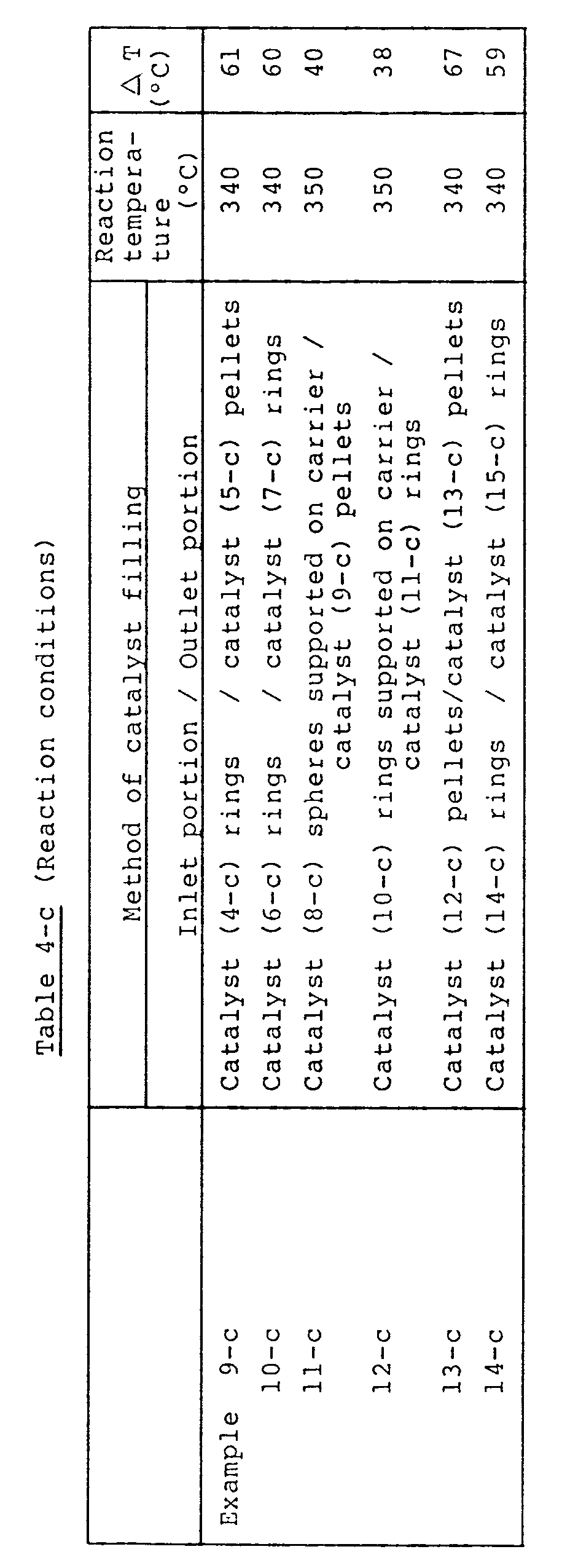

Claims (8)
- A process for producing methacrolein and methacrylic acid by subjecting at least one material selected from isobutylene, t-butanol and methyl t-butyl ether to gas phase catalytic oxidation with molecular oxygen or a molecular oxygen-containing gas using a fixed bed multi-tubular reactor, said process
(α) using as catalysts, compound oxides represented by the following general formula (I)
MoaWbBicFedAeBfCgDhEiOx
(in the formula, Mo represents molybdenum, W represents tungsten, Bi represents bismuth, Fe represents iron, A represents at least one element selected from nickel and cobalt, B represents at least one element selected from alkali metals and thallium, C represents at least one element selected from alkaline earth metals, D represents at least one element selected from phosphorus, tellurium, antimony, tin, cerium, lead, niobium, manganese, arsenic and zinc, E represents at least one element selected from silicon, aluminum, titanium and zirconium, and O represents oxygen; a, b, c, d, e, f, g, h, i and x represent the numbers of atoms of Mo, W, Bi, Fe, A, B, C, D, E and O, respectively; when a is 12, b = 0-10, c = 0.1-20, d = 0.1-20, e = 2-20, f = 0-10, g = 0-10, h = 0-4, i = 0-30 and x = a value determined by the oxidation states of individual elements), characterized in that
(β) each reaction tube has a plurality of reaction zones formed by dividing the catalyst layer in the reaction tube into two or more portions in the axial direction of the tube, and (γ) the plurality of reaction zones are filled with catalysts shown in the above (α) having different activities, prepared by varying the types and/or amounts of the elements constituting the A group, C group, D group and E group in the general formula (I) and/or with catalysts shown in the above (α) having different activities, prepared by varying the amount of at least one element of W, Bi and Fe in the general formula (I), in such a way that the activity of filled catalyst becomes higher as a material gas proceeds from the inlet to the outlet. - The process for producing methacrolein and metbacrylic acid according to Claim 1, which uses catalysts of different activities prepared by varying the types and/or amounts of the elements constituting the A group, C group, D group and E group in the general formula (I) and further by varying the firing temperature employed in catalyst preparation, and/or catalysts of different activities prepared by varying the amount of at least one element of W, Bi and Fe in the general formula (I) and further by varying the firing temperature employed in catalyst preparation.
- The process for producing methacrolein and methacrylic acid according to Claim 1, which uses catalysts of the general formula (I) (wherein when a is 12, b = 0-10, c = 0.1-10, d = 0.1-20, e = 2-20, f = 0-10, g = 0.001-10, h = 0-4, i = 0-30 and x = a value determined by the oxidation states of individual elements) of different activities, prepared by varying the type(s) and/or amount(s) of the C group element(s) in the general formula (I).
- The process for producing methacrolein and methacrylic acid according to Claim 3, which uses catalysts of different activities prepared by varying the type(s) and/or amount(s) of the C group element(s) in the general formula (I) and further by varying the firing temperature employed in catalyst preparation.
- The process for producing methacrolein and methacrylic acid according to Claim 1, which uses catalysts of the general formula (I) (wherein when a is 12, b = 0-10, c = 0.1-10, d = 0.1-20, e = 2-20, f = 0-10, g = 0-10, h = 0-4, i = 0-30 and x = a value determined by the oxidation states of individual elements, with a proviso that b, h and i do not take a value of 0 independently) of different activities, prepared by varying the types and/or amounts of the elements constituting the A group, D group and E group in the general formula (I), and/or catalysts of the general formula (I) (wherein when a is 12, b = 0-10, c = 0.1-10, d = 0.1-20, e = 2-20, f = 0-10, g = 0-10, h = 0-4, i = 0-30 and x = a value determined by the oxidation states of individual elements, with a proviso that b, h and i do not take a value of 0 independently) of different activities, prepared by varying the amount of at least one element of W, Bi and Fe in the general formula (I).
- The process for producing methacrolein and methacrylic acid according to Claim 5, which uses catalysts of different activities prepared by varying the types and/or amounts of the elements constituting the A group, D group and E group in the general formula (I) and further by varying the firing temperature employed in catalyst preparation, and/or catalysts of different activities prepared by varying the amount of at least one element of W, Bi and Fe in the general formula (I) and further by varying the firing temperature employed in catalyst preparation.
- The process for producing methacrolein and methacrylic acid according to any of Claims 1 to 6, wherein the number of the reaction zones is 2 or 3.
- The process for producing methacrolein and methacrylic acid according to any of Claims 1 to 7, wherein the catalysts are ring-shaped catalysts with a through-hole in the length direction, having an outside diameter of 3-10 mm, a length of 0.5-2 times the outside diameter and an inside diameter (the diameter of the through-hole) of 0.1-0.7 time the outside diameter.
Applications Claiming Priority (9)
| Application Number | Priority Date | Filing Date | Title |
|---|---|---|---|
| JP1315163A JP2934267B2 (en) | 1989-12-06 | 1989-12-06 | Method for producing methacrolein and methacrylic acid |
| JP315163/89 | 1989-12-06 | ||
| JP338471/89 | 1989-12-28 | ||
| JP1338471A JP2756160B2 (en) | 1989-12-28 | 1989-12-28 | Method for producing methacrolein and methacrylic acid |
| JP7200/90 | 1990-01-18 | ||
| JP2007200A JP2638241B2 (en) | 1990-01-18 | 1990-01-18 | Method for producing methacrolein and methacrylic acid |
| JP14815/90 | 1990-01-26 | ||
| JP2014815A JP2659839B2 (en) | 1990-01-26 | 1990-01-26 | Method for producing methacrolein and methacrylic acid |
| EP91900057A EP0456837B1 (en) | 1989-12-06 | 1990-12-06 | Process for producing methacrolein and methacrylic acid |
Related Parent Applications (2)
| Application Number | Title | Priority Date | Filing Date |
|---|---|---|---|
| EP91900057.0 Division | 1990-12-06 | ||
| EP91900057A Division EP0456837B1 (en) | 1989-12-06 | 1990-12-06 | Process for producing methacrolein and methacrylic acid |
Publications (2)
| Publication Number | Publication Date |
|---|---|
| EP0608917A1 true EP0608917A1 (en) | 1994-08-03 |
| EP0608917B1 EP0608917B1 (en) | 1999-04-21 |
Family
ID=27454664
Family Applications (2)
| Application Number | Title | Priority Date | Filing Date |
|---|---|---|---|
| EP94103673A Expired - Lifetime EP0608917B1 (en) | 1989-12-06 | 1990-12-06 | Process for producing methacrolein and methacrylic acid |
| EP91900057A Expired - Lifetime EP0456837B1 (en) | 1989-12-06 | 1990-12-06 | Process for producing methacrolein and methacrylic acid |
Family Applications After (1)
| Application Number | Title | Priority Date | Filing Date |
|---|---|---|---|
| EP91900057A Expired - Lifetime EP0456837B1 (en) | 1989-12-06 | 1990-12-06 | Process for producing methacrolein and methacrylic acid |
Country Status (7)
| Country | Link |
|---|---|
| US (1) | US5276178A (en) |
| EP (2) | EP0608917B1 (en) |
| KR (1) | KR950006522B1 (en) |
| DE (2) | DE69028843T2 (en) |
| ES (2) | ES2092557T3 (en) |
| SG (1) | SG50687A1 (en) |
| WO (1) | WO1991008185A1 (en) |
Cited By (2)
| Publication number | Priority date | Publication date | Assignee | Title |
|---|---|---|---|---|
| EP1052017A3 (en) * | 1999-05-13 | 2002-05-22 | Nippon Shokubai Co., Ltd | Catalyst containing Mo, Bi, Fe, Ce and Zr; its use in the production of unsaturated aldehyde and unsaturated carboxylic acid |
| US9206108B2 (en) | 2007-05-25 | 2015-12-08 | Evonik Roehm Gmbh | Use of a feed compositions in preparation of methacrylic acid by oxidation |
Families Citing this family (50)
| Publication number | Priority date | Publication date | Assignee | Title |
|---|---|---|---|---|
| JP3272745B2 (en) * | 1991-06-06 | 2002-04-08 | 三菱レイヨン株式会社 | Method for producing methacrolein and methacrylic acid |
| JP2974826B2 (en) * | 1991-07-17 | 1999-11-10 | 三菱レイヨン株式会社 | Preparation of catalysts for the production of methacrolein and methacrylic acid |
| DE69407669T3 (en) * | 1993-06-25 | 2002-04-25 | Sumitomo Chemical Co | Process for the preparation of an unsaturated aldehyde and an unsaturated carboxylic acid |
| TW309513B (en) * | 1994-05-31 | 1997-07-01 | Nippon Catalytic Chem Ind | |
| US5728894A (en) * | 1994-06-22 | 1998-03-17 | Ashahi Kasei Kogyo Kabushiki Kaisha | Method for producing methacrolein |
| US6136998A (en) * | 1996-10-15 | 2000-10-24 | Mitsubishi Rayon Co., Ltd. | Retention of activity of molybdenum-containing metallic oxide catalyst |
| JP3775872B2 (en) * | 1996-12-03 | 2006-05-17 | 日本化薬株式会社 | Method for producing acrolein and acrylic acid |
| US5864051A (en) * | 1997-11-10 | 1999-01-26 | Uop | Selective oxidation catalyst process for preparing the catalyst and process using the catalyst |
| JP4045693B2 (en) * | 1999-04-27 | 2008-02-13 | 住友化学株式会社 | Method for producing methacrylic acid |
| JP4185217B2 (en) * | 1999-05-25 | 2008-11-26 | 株式会社日本触媒 | Composite oxide catalyst and method for producing (meth) acrolein and (meth) acrylic acid |
| JP3943291B2 (en) | 1999-08-04 | 2007-07-11 | 株式会社日本触媒 | Method for producing acrolein and acrylic acid |
| JP3943311B2 (en) | 2000-05-19 | 2007-07-11 | 株式会社日本触媒 | Process for producing unsaturated aldehyde and unsaturated carboxylic acid |
| DE10046957A1 (en) * | 2000-09-21 | 2002-04-11 | Basf Ag | Process for producing a multimetal oxide catalyst, process for producing unsaturated aldehydes and / or carboxylic acids and band calciner |
| DE10063162A1 (en) * | 2000-12-18 | 2002-06-20 | Basf Ag | Process for the preparation of a Mo, Bi, Fe and Ni and / or Co-containing multimetal oxide |
| TW572885B (en) * | 2001-05-30 | 2004-01-21 | Mitsubishi Rayon Co | Method for producing (meth)acrolein and/or (meth)acrylic acid |
| BR0214811A (en) * | 2001-12-27 | 2004-12-14 | Mitsubishi Chem Corp | Process for catalytic gas phase oxidation and process for the production of (meth) acrolein or (meth) acrylic acid |
| CN1607032A (en) * | 2001-12-28 | 2005-04-20 | 三菱化学株式会社 | Method for vapor phase catalytic oxidation |
| JP3884967B2 (en) * | 2002-02-07 | 2007-02-21 | 住友化学株式会社 | Method for producing methacrylic acid |
| US6960684B2 (en) * | 2002-03-29 | 2005-11-01 | Nippon Shokubai Co., Ltd. | Production process for unsaturated aldehyde |
| US7045657B2 (en) * | 2002-04-03 | 2006-05-16 | Nippon Shokubai Co., Ltd. | Catalytic gas phase oxidation process |
| US6946422B2 (en) * | 2002-12-12 | 2005-09-20 | Saudi Basic Industries Corporation | Preparation of mixed metal oxide catalysts for catalytic oxidation of olefins to unsaturated aldehydes |
| US20040192973A1 (en) * | 2003-03-31 | 2004-09-30 | Saudi Basic Industries Corporation | Mixed metal oxide catalysts for the production of unsaturated aldehydes from olefins |
| US7361791B2 (en) * | 2003-03-31 | 2008-04-22 | Saudi Basic Industries Corporation | Mixed metal oxide catalysts for the production of unsaturated aldehydes from olefins |
| US7232788B2 (en) * | 2003-03-31 | 2007-06-19 | Saudi Basic Industries Corporation | Mixed metal oxide catalysts for the production of unsaturated aldehydes from olefins |
| US7161044B2 (en) * | 2003-10-22 | 2007-01-09 | Nippon Shokubai Co., Ltd. | Catalytic gas phase oxidation reaction |
| CN1697794A (en) * | 2003-12-03 | 2005-11-16 | 三菱化学株式会社 | Process for producing unsaturated aldehyde and unsaturated carboxylic acid |
| US7229945B2 (en) * | 2003-12-19 | 2007-06-12 | Saudi Basic Industrics Corporation | Process of making mixed metal oxide catalysts for the production of unsaturated aldehydes from olefins |
| JP2005213179A (en) * | 2004-01-29 | 2005-08-11 | Mitsubishi Rayon Co Ltd | Catalyst layer and method for forming the same, fixed bed tubular reactor, method for producing methacrolein or methacrylic acid |
| EP1748839B1 (en) | 2004-05-07 | 2020-04-01 | Basf Se | Method for structurally filling contact tubes of a bank of contact tubes |
| JP4572573B2 (en) * | 2004-05-13 | 2010-11-04 | 三菱化学株式会社 | Method for producing (meth) acrolein or (meth) acrylic acid |
| US7649112B2 (en) | 2005-07-25 | 2010-01-19 | Saudi Basic Industries Corporation | Integrated plant for producing 2-ethyl-hexanol and methacrylic acid and a method based thereon |
| US7732367B2 (en) * | 2005-07-25 | 2010-06-08 | Saudi Basic Industries Corporation | Catalyst for methacrolein oxidation and method for making and using same |
| US7649111B2 (en) * | 2005-07-25 | 2010-01-19 | Saudi Basic Industries Corporation | Catalyst for the oxidation of a mixed aldehyde feedstock to methacrylic acid and methods for making and using same |
| US7851397B2 (en) * | 2005-07-25 | 2010-12-14 | Saudi Basic Industries Corporation | Catalyst for methacrolein oxidation and method for making and using same |
| US7799946B2 (en) * | 2007-02-14 | 2010-09-21 | Saudi Basic Industries Corporation | Process for separating methacrolein from methacrylic acid in a gas phase product from the partial oxidation of isobutene |
| DE102007017080A1 (en) | 2007-04-10 | 2008-10-16 | Basf Se | Method for feeding a longitudinal section of a contact tube |
| DE102007025869A1 (en) | 2007-06-01 | 2008-07-03 | Basf Se | To service tube bundle of gas-phase hydrocarbon oxidation reactor immediately prior to re-charging with fresh bed of catalyst solids, they are brushed internally |
| DE102007028332A1 (en) | 2007-06-15 | 2008-12-18 | Basf Se | A method for feeding a reactor with a fixed catalyst bed comprising at least annular shaped catalyst bodies K. |
| EP2085376B1 (en) | 2008-01-30 | 2012-09-05 | Evonik Röhm GmbH | Process for preparation of high purity methacrylic acid |
| KR101072177B1 (en) * | 2009-06-08 | 2011-10-10 | 주식회사 엘지화학 | Catalyst for Hydrocarbon Steam Cracking, Method for Preparing the Same and Method for Preparing Olefin by Using the Same |
| US8921257B2 (en) | 2011-12-02 | 2014-12-30 | Saudi Basic Industries Corporation | Dual function partial oxidation catalyst for propane to acrylic acid conversion |
| US8722940B2 (en) | 2012-03-01 | 2014-05-13 | Saudi Basic Industries Corporation | High molybdenum mixed metal oxide catalysts for the production of unsaturated aldehydes from olefins |
| WO2013163806A1 (en) | 2012-05-03 | 2013-11-07 | Evonik Industries Ag | Process for preparation of highly pure, non-yellowing methacrylic acid |
| SG11201507796VA (en) | 2013-03-18 | 2015-10-29 | Evonik Roehm Gmbh | Process for preparation of methacrylic acid and methacrylic acid esters |
| US9656248B2 (en) | 2013-05-09 | 2017-05-23 | Nippon Kayaku Kabushiki Kaisha | Catalyst for producing unsaturated aldehyde and/or unsaturated carboxylic acid, method for producing same, and method for producing unsaturated aldehyde and/or unsaturated carboxylic acid |
| KR20160032037A (en) | 2013-07-18 | 2016-03-23 | 닛뽄 가야쿠 가부시키가이샤 | Method for producing unsaturated aldehyde and/or unsaturated carboxylic acid |
| CN104649872B (en) * | 2013-11-19 | 2016-08-17 | 中国石油天然气股份有限公司 | A kind of method of selectivity of light olefin oxidation |
| CN105801394B (en) * | 2014-12-31 | 2018-10-02 | 上海华谊新材料有限公司 | The method that methacrolein is prepared by the tert-butyl alcohol |
| JP6694884B2 (en) * | 2015-07-10 | 2020-05-20 | 日本化薬株式会社 | Process for producing unsaturated aldehyde and / or unsaturated carboxylic acid |
| CN115260015A (en) * | 2021-04-29 | 2022-11-01 | 中国石油化工股份有限公司 | Method for preparing methacrolein and methacrylic acid |
Citations (4)
| Publication number | Priority date | Publication date | Assignee | Title |
|---|---|---|---|---|
| FR2114414A5 (en) * | 1970-11-18 | 1972-06-30 | Basf Ag | |
| DE3006894A1 (en) * | 1979-02-26 | 1980-09-04 | Mitsubishi Petrochemical Co | PRODUCTION OF ACROLEIN AND ACRYLIC ACID |
| GB2063861A (en) * | 1979-11-19 | 1981-06-10 | Mitsubishi Petrochemical Co | Process for producing acrylic acid |
| DE3308625A1 (en) * | 1983-03-11 | 1984-09-13 | Basf Ag, 6700 Ludwigshafen | METHOD AND CATALYST FOR PRODUCING METHACRYLIC ACID |
Family Cites Families (19)
| Publication number | Priority date | Publication date | Assignee | Title |
|---|---|---|---|---|
| JPS5541213B2 (en) * | 1972-07-21 | 1980-10-22 | ||
| JPS5761011B2 (en) * | 1973-12-28 | 1982-12-22 | Nippon Shokubai Kagaku Kogyo Kk | |
| US4001317A (en) * | 1974-07-22 | 1977-01-04 | Standard Oil Company | Process for the oxidation of olefins using catalysts containing various promoter elements |
| IN142430B (en) * | 1975-04-21 | 1977-07-09 | Standard Oil Co | |
| US4323520A (en) * | 1976-08-02 | 1982-04-06 | The Standard Oil Co. | Preparation of methacrylic derivatives from tertiary-butyl-containing compounds |
| JPS543008A (en) * | 1977-06-09 | 1979-01-11 | Japan Synthetic Rubber Co Ltd | Preparation of methacrylic acid |
| JPS5547144A (en) * | 1977-08-10 | 1980-04-03 | Standard Oil Co | Multiple component oxide complex catalyst forming technique |
| US4148757A (en) * | 1977-08-10 | 1979-04-10 | The Standard Oil Company | Process for forming multi-component oxide complex catalysts |
| US4267386A (en) * | 1978-11-13 | 1981-05-12 | Celanese Corporation | Olefin oxidation catalyst |
| JPS5687530A (en) * | 1979-12-19 | 1981-07-16 | Asahi Chem Ind Co Ltd | Dehydrating method of gas containing unsaturated aldehyde |
| JPS56166140A (en) * | 1980-05-24 | 1981-12-21 | Asahi Chem Ind Co Ltd | Preparation of methacrolein |
| JPS58119346A (en) * | 1982-01-06 | 1983-07-15 | Nippon Shokubai Kagaku Kogyo Co Ltd | Catalyst for oxidizing propylene |
| JPS58143843A (en) * | 1982-02-17 | 1983-08-26 | ザ・スタンダ−ド・オイル・カンパニー | Catalyst available for oxidation or ammonia oxidation of olefin |
| JPS5946132A (en) * | 1982-09-06 | 1984-03-15 | Nippon Shokubai Kagaku Kogyo Co Ltd | Catalyst for synthesis of methacrolein |
| JPS59115750A (en) * | 1982-12-22 | 1984-07-04 | Nippon Shokubai Kagaku Kogyo Co Ltd | Catalyst for synthesis of methacrylic acid |
| JPS6122040A (en) * | 1984-07-10 | 1986-01-30 | Mitsubishi Rayon Co Ltd | Production of methacrolein and methacrylic acid |
| JPH0625085B2 (en) * | 1984-07-24 | 1994-04-06 | 三菱レイヨン株式会社 | Method for producing methacrolein and methacrylic acid |
| DE3562482D1 (en) * | 1984-07-18 | 1988-06-09 | Mitsubishi Rayon Co | Process for producing methacrolein and methacrylic acid |
| US5208371A (en) * | 1986-11-11 | 1993-05-04 | Mitsubishi Rayon Co., Ltd. | Process for production of methacrolein and methacrylic acid |
-
1990
- 1990-12-06 SG SG1996008755A patent/SG50687A1/en unknown
- 1990-12-06 WO PCT/JP1990/001594 patent/WO1991008185A1/en active IP Right Grant
- 1990-12-06 ES ES91900057T patent/ES2092557T3/en not_active Expired - Lifetime
- 1990-12-06 DE DE69028843T patent/DE69028843T2/en not_active Expired - Lifetime
- 1990-12-06 DE DE69033068T patent/DE69033068T2/en not_active Expired - Lifetime
- 1990-12-06 KR KR1019910700846A patent/KR950006522B1/en not_active IP Right Cessation
- 1990-12-06 EP EP94103673A patent/EP0608917B1/en not_active Expired - Lifetime
- 1990-12-06 ES ES94103673T patent/ES2130297T3/en not_active Expired - Lifetime
- 1990-12-06 US US07/721,574 patent/US5276178A/en not_active Expired - Lifetime
- 1990-12-06 EP EP91900057A patent/EP0456837B1/en not_active Expired - Lifetime
Patent Citations (4)
| Publication number | Priority date | Publication date | Assignee | Title |
|---|---|---|---|---|
| FR2114414A5 (en) * | 1970-11-18 | 1972-06-30 | Basf Ag | |
| DE3006894A1 (en) * | 1979-02-26 | 1980-09-04 | Mitsubishi Petrochemical Co | PRODUCTION OF ACROLEIN AND ACRYLIC ACID |
| GB2063861A (en) * | 1979-11-19 | 1981-06-10 | Mitsubishi Petrochemical Co | Process for producing acrylic acid |
| DE3308625A1 (en) * | 1983-03-11 | 1984-09-13 | Basf Ag, 6700 Ludwigshafen | METHOD AND CATALYST FOR PRODUCING METHACRYLIC ACID |
Cited By (5)
| Publication number | Priority date | Publication date | Assignee | Title |
|---|---|---|---|---|
| EP1052017A3 (en) * | 1999-05-13 | 2002-05-22 | Nippon Shokubai Co., Ltd | Catalyst containing Mo, Bi, Fe, Ce and Zr; its use in the production of unsaturated aldehyde and unsaturated carboxylic acid |
| SG89327A1 (en) * | 1999-05-13 | 2002-06-18 | Nippon Catalytic Chem Ind | Catalysts for production of unsaturated aldehyde and unsaturated carboxylic acid and a process for producing unsaturated aldehyde and unsaturated carboxylic acid using the catalysts |
| US6583316B1 (en) | 1999-05-13 | 2003-06-24 | Nippon Shokubai Co., Ltd. | Catalysts for production of unsaturated aldehyde and unsaturated carboxylic acid and a process for producing unsaturated aldehyde and unsaturated carboxylic acid using the catalysts |
| US9206108B2 (en) | 2007-05-25 | 2015-12-08 | Evonik Roehm Gmbh | Use of a feed compositions in preparation of methacrylic acid by oxidation |
| EP1995232B1 (en) * | 2007-05-25 | 2018-01-03 | Evonik Röhm GmbH | Use of feed compositions in preparation of methacrylic acid by oxidation |
Also Published As
| Publication number | Publication date |
|---|---|
| EP0456837A1 (en) | 1991-11-21 |
| DE69028843T2 (en) | 1997-02-27 |
| KR920701099A (en) | 1992-08-11 |
| SG50687A1 (en) | 1998-07-20 |
| EP0456837A4 (en) | 1992-01-15 |
| DE69033068T2 (en) | 1999-08-19 |
| ES2130297T3 (en) | 1999-07-01 |
| ES2092557T3 (en) | 1996-12-01 |
| EP0608917B1 (en) | 1999-04-21 |
| US5276178A (en) | 1994-01-04 |
| WO1991008185A1 (en) | 1991-06-13 |
| EP0456837B1 (en) | 1996-10-09 |
| DE69033068D1 (en) | 1999-05-27 |
| DE69028843D1 (en) | 1996-11-14 |
| KR950006522B1 (en) | 1995-06-16 |
Similar Documents
| Publication | Publication Date | Title |
|---|---|---|
| US5276178A (en) | Process for producing methacrolein and methacrylic acid | |
| EP1055662B1 (en) | A process for producing acrylic acid | |
| US4537874A (en) | Catalyst for production of unsaturated aldehydes | |
| US7531147B2 (en) | Method of producing unsaturated aldehyde and/or unsaturated acid | |
| US6781013B2 (en) | Process for producing acrolein and acrylic acid | |
| JPH0784400B2 (en) | Process for producing unsaturated aldehyde and unsaturated acid | |
| US5206431A (en) | Process for producing methacrylic acid | |
| KR100661727B1 (en) | Method of producing unsaturated aldehyde and/or unsaturated fatty acid | |
| JP2574948B2 (en) | Method for producing methacrylic acid | |
| JP3139285B2 (en) | Method for producing acrolein and acrylic acid | |
| JP4824867B2 (en) | Method for producing methacrolein and methacrylic acid | |
| JP2002212127A (en) | Method for producing methacrolein and methacrylic acid | |
| EP0441312B1 (en) | Process for producing methacrylic acid | |
| JP4824871B2 (en) | Method for producing acrolein and acrylic acid | |
| JP2988660B2 (en) | Method for producing methacrolein and methacrylic acid | |
| JP2659839B2 (en) | Method for producing methacrolein and methacrylic acid | |
| JP2638241B2 (en) | Method for producing methacrolein and methacrylic acid | |
| JP2934267B2 (en) | Method for producing methacrolein and methacrylic acid | |
| JP2000351744A (en) | Method for producing methacrolein and methacrylic acid | |
| JP2863509B2 (en) | Method for producing methacrolein and methacrylic acid | |
| JP2756160B2 (en) | Method for producing methacrolein and methacrylic acid | |
| JPH09194409A (en) | Production of methacrolein and methacrylic acid |
Legal Events
| Date | Code | Title | Description |
|---|---|---|---|
| PUAI | Public reference made under article 153(3) epc to a published international application that has entered the european phase |
Free format text: ORIGINAL CODE: 0009012 |
|
| AC | Divisional application: reference to earlier application |
Ref document number: 456837 Country of ref document: EP |
|
| AK | Designated contracting states |
Kind code of ref document: A1 Designated state(s): BE DE ES FR GB IT NL |
|
| 17P | Request for examination filed |
Effective date: 19950118 |
|
| 17Q | First examination report despatched |
Effective date: 19951115 |
|
| GRAG | Despatch of communication of intention to grant |
Free format text: ORIGINAL CODE: EPIDOS AGRA |
|
| GRAG | Despatch of communication of intention to grant |
Free format text: ORIGINAL CODE: EPIDOS AGRA |
|
| GRAG | Despatch of communication of intention to grant |
Free format text: ORIGINAL CODE: EPIDOS AGRA |
|
| GRAH | Despatch of communication of intention to grant a patent |
Free format text: ORIGINAL CODE: EPIDOS IGRA |
|
| GRAH | Despatch of communication of intention to grant a patent |
Free format text: ORIGINAL CODE: EPIDOS IGRA |
|
| GRAA | (expected) grant |
Free format text: ORIGINAL CODE: 0009210 |
|
| AC | Divisional application: reference to earlier application |
Ref document number: 456837 Country of ref document: EP |
|
| AK | Designated contracting states |
Kind code of ref document: B1 Designated state(s): BE DE ES FR GB IT NL |
|
| REF | Corresponds to: |
Ref document number: 69033068 Country of ref document: DE Date of ref document: 19990527 |
|
| REG | Reference to a national code |
Ref country code: ES Ref legal event code: FG2A Ref document number: 2130297 Country of ref document: ES Kind code of ref document: T3 |
|
| ET | Fr: translation filed | ||
| PLBE | No opposition filed within time limit |
Free format text: ORIGINAL CODE: 0009261 |
|
| STAA | Information on the status of an ep patent application or granted ep patent |
Free format text: STATUS: NO OPPOSITION FILED WITHIN TIME LIMIT |
|
| 26N | No opposition filed | ||
| PGFP | Annual fee paid to national office [announced via postgrant information from national office to epo] |
Ref country code: GB Payment date: 20011205 Year of fee payment: 12 |
|
| PGFP | Annual fee paid to national office [announced via postgrant information from national office to epo] |
Ref country code: NL Payment date: 20011228 Year of fee payment: 12 |
|
| REG | Reference to a national code |
Ref country code: GB Ref legal event code: IF02 |
|
| PG25 | Lapsed in a contracting state [announced via postgrant information from national office to epo] |
Ref country code: GB Free format text: LAPSE BECAUSE OF NON-PAYMENT OF DUE FEES Effective date: 20021206 |
|
| PG25 | Lapsed in a contracting state [announced via postgrant information from national office to epo] |
Ref country code: NL Free format text: LAPSE BECAUSE OF NON-PAYMENT OF DUE FEES Effective date: 20030701 |
|
| GBPC | Gb: european patent ceased through non-payment of renewal fee | ||
| NLV4 | Nl: lapsed or anulled due to non-payment of the annual fee |
Effective date: 20030701 |
|
| BECA | Be: change of holder's address |
Owner name: *SUMITOMO CHIMICAL CO. LTD27-1, SHINKAWA 2-CHOME, Effective date: 20051027 |
|
| REG | Reference to a national code |
Ref country code: FR Ref legal event code: TP |
|
| BECA | Be: change of holder's address |
Owner name: *SUMITOMO CHIMICAL CO. LTD27-1, SHINKAWA 2-CHOME, Effective date: 20051027 |
|
| PGFP | Annual fee paid to national office [announced via postgrant information from national office to epo] |
Ref country code: BE Payment date: 20081017 Year of fee payment: 19 |
|
| PGFP | Annual fee paid to national office [announced via postgrant information from national office to epo] |
Ref country code: FR Payment date: 20081212 Year of fee payment: 19 Ref country code: ES Payment date: 20090113 Year of fee payment: 19 |
|
| PGFP | Annual fee paid to national office [announced via postgrant information from national office to epo] |
Ref country code: IT Payment date: 20081229 Year of fee payment: 19 |
|
| BERE | Be: lapsed |
Owner name: *SUMITOMO CHIMICAL CO. LTD Effective date: 20091231 |
|
| PGFP | Annual fee paid to national office [announced via postgrant information from national office to epo] |
Ref country code: DE Payment date: 20091203 Year of fee payment: 20 |
|
| REG | Reference to a national code |
Ref country code: FR Ref legal event code: ST Effective date: 20100831 |
|
| PG25 | Lapsed in a contracting state [announced via postgrant information from national office to epo] |
Ref country code: FR Free format text: LAPSE BECAUSE OF NON-PAYMENT OF DUE FEES Effective date: 20091231 Ref country code: BE Free format text: LAPSE BECAUSE OF NON-PAYMENT OF DUE FEES Effective date: 20091231 |
|
| REG | Reference to a national code |
Ref country code: ES Ref legal event code: FD2A Effective date: 20110225 |
|
| PG25 | Lapsed in a contracting state [announced via postgrant information from national office to epo] |
Ref country code: IT Free format text: LAPSE BECAUSE OF NON-PAYMENT OF DUE FEES Effective date: 20091206 |
|
| PG25 | Lapsed in a contracting state [announced via postgrant information from national office to epo] |
Ref country code: ES Free format text: LAPSE BECAUSE OF EXPIRATION OF PROTECTION Effective date: 20101207 |
|
| PG25 | Lapsed in a contracting state [announced via postgrant information from national office to epo] |
Ref country code: DE Free format text: LAPSE BECAUSE OF EXPIRATION OF PROTECTION Effective date: 20101206 |
|
| PG25 | Lapsed in a contracting state [announced via postgrant information from national office to epo] |
Ref country code: ES Free format text: LAPSE BECAUSE OF EXPIRATION OF PROTECTION Effective date: 20091207 |