EP0608833A2 - Verfahren und Vorrichtung zur Durchführung einer Zeitskalenmodifikation von Sprachsignalen - Google Patents
Verfahren und Vorrichtung zur Durchführung einer Zeitskalenmodifikation von Sprachsignalen Download PDFInfo
- Publication number
- EP0608833A2 EP0608833A2 EP94101057A EP94101057A EP0608833A2 EP 0608833 A2 EP0608833 A2 EP 0608833A2 EP 94101057 A EP94101057 A EP 94101057A EP 94101057 A EP94101057 A EP 94101057A EP 0608833 A2 EP0608833 A2 EP 0608833A2
- Authority
- EP
- European Patent Office
- Prior art keywords
- signal
- time
- time length
- window function
- time delay
- Prior art date
- Legal status (The legal status is an assumption and is not a legal conclusion. Google has not performed a legal analysis and makes no representation as to the accuracy of the status listed.)
- Granted
Links
Images


Classifications
-
- G—PHYSICS
- G10—MUSICAL INSTRUMENTS; ACOUSTICS
- G10L—SPEECH ANALYSIS OR SYNTHESIS; SPEECH RECOGNITION; SPEECH OR VOICE PROCESSING; SPEECH OR AUDIO CODING OR DECODING
- G10L21/00—Processing of the speech or voice signal to produce another audible or non-audible signal, e.g. visual or tactile, in order to modify its quality or its intelligibility
- G10L21/04—Time compression or expansion
Definitions
- the present invention relates to a method of and an apparatus for performing time-scale modification of a speech signal, whereby the time duration of the speech signal is changed without changing the fundamental frequency components of the speech signal.
- This speech time-scale modification apparatus includes a variable delay line, a ramp level and amplitude changer, a blanking circuit, a blanking pulse generator, and a ramp pulse-train generator.
- the ramp pulse-train generator controls the ramp level and amplitude changer and the blanking pulse generator in accordance with the time-scale modification ratio.
- the ramp level and amplitude changer then reads the input signal from the variable delay line at a speed which is different from a speed in writing in accordance with the time-scale modification ratio. Specifically, for a playback of a speech signal at a higher speed, reading is done at a lower rate than writing, and for a playback of a speech signal at a lower speed, reading is done at a higher rate than writing.
- the blanking circuit applies the muting action to the output of the variable delay line.
- TDHS Time Domain Harmonic Scaling
- Be time-scale expansion
- the TDHS uses a pitch period, but it is difficult to accurately extract the pitch period. In particular, it is extremely difficult to extract a pitch period from a music signal or a signal superposed with noise. As a result, it is difficult to sample an input signal using the length (Bc or Be) that is set in terms of the pitch period p, and by overlapping or connecting input signals sampled on the basis of an incorrect pitch period, an output signal of good quality cannot be obtained.
- the apparatus of this invention for transforming an input signal having a time length L into an output signal having a time length ⁇ L in accordance with a given time-scale modification ratio ⁇ , includes: an input section for inputting a first signal which has a time length T and a second signal which has the time length T and succeeds the first signal; a correlator for calculating a value of a correlation function between the first signal and the second signal and for determining a time delay Tc at which the value of the correlation function becomes the greatest; a window function generator for generating a first window function and a second window function according to the time-scale modification ratio ⁇ and the time delay Tc; a first multiplier for multiplying the first signal by the first window function; a second multiplier for multiplying the second signal by the second window function; an adder for adding the output of the first multiplier to the output of the second multiplier with a displacement of the time delay Tc; and an outputting section for selectively outputting the output of the adder and a third signal succeeding the output
- a method for transforming an input signal having a time length L into an output signal having a time length ⁇ L in accordance with a given time-scale modification ratio ⁇ includes the steps of: (a) inputting a first signal which has a time length T from a starting point and a second signal which has the time length T and succeeds the first signal; (b) calculating a value of a correlation function between the first signal and the second signal and determining a time delay Tc at which the value of the correlation function becomes the greatest; (c) generating a first window function and a second window function according to the time-scale modification ratio ⁇ and the time delay Tc; (d) obtaining a first multiplied result by multiplying the first signal by the first window function; (e) obtaining a second multiplied result by multiplying the second signal by the second window function; (f) obtaining an added result by adding the first multiplied result to the second multiplied result with a displacement of the time delay Tc; (g) selective
- the time-scale modification ratio ⁇ satisfies a condition of ⁇ ⁇ 1
- the first window function monotonically increases and the second window function monotonically decreases in a manner complementary to the first window function
- the predetermined first time length is represented by ⁇ (T - Tc)/( ⁇ - 1)
- said third signal is a signal exceeding said first signal
- the predetermined second time length is represented by (T - Tc)/( ⁇ - 1) .
- the time-scale modification ratio ⁇ satisfies a condition of ⁇ ⁇ 1
- the first window function monotonically decreases and the second window function monotonically increases in a manner complementary to the first window function
- the predetermined first time length is represented by an equation of ⁇ (T - Tc)/(1 - ⁇ )
- said third signal is a signal exceeding said second signal
- the predetermined second time length is represented by an equation of (T - Tc)/(1 - ⁇ ) .
- an apparatus for transforming an input signal having a time length L into an output signal having a time length ⁇ L in accordance with a given time-scale modification ratio ⁇ includes: an input section for inputting a first signal which has a time length M (T ⁇ M ⁇ 2T) and a second signal which has the time length M, the starting point of the second signal being delayed from the starting point of the first signal by a time length T; a correlator for calculating a value of a correlation function between the first signal and the second signal and for determining a time delay Tc at which the value of the correlation function becomes the greatest; a window function generator for generating a first window function and a second window function according to the time-scale modification ratio ⁇ and the time delay Tc; a reading circuit for reading a portion of the first signal and a portion of the second signal according to the time delay Tc; a first multiplier for multiplying the portion of the first signal by the first window function; a second multiplier for multiplying the
- a method for transforming an input signal having a time length L into an output signal having a time length ⁇ L in accordance with a given time-scale modification ratio ⁇ which satisfies a condition of ⁇ ⁇ includes the steps of: (a) inputting a first signal which has a time length T from a starting point and a second signal which has the time length T and succeeds the first signal; (b) calculating a value of a correlation function between the first signal and the second signal and determining a time delay Tc at which the value of the correlation function becomes the greatest; (c) obtaining a third signal which has the time length T and delays from the first signal by the time delay Tc and a fourth signal which has the time length T and delays from the second signal by the time delay (-Tc); (d) generating a first window function which monotonically increases and a second window function which monotonically decreases in a manner complementary to the first window function according to the time-scale modification ratio ⁇ and the time delay Tc;
- the predetermined first time length is represented by an equation of ⁇ (T - Tc)/( ⁇ - 1) and the predetermined second time length is represented by an equation of (T - Tc)/( ⁇ - 1) .
- the step (b) includes the steps of: calculating a value of a correlation function between the first signal and a signal which has the time length T and delays from the second signal by (- ⁇ ) for -T ⁇ ⁇ ⁇ 0; calculating a value of said correlation function between the second signal and a signal which has the time length T and delays from the first signal by ⁇ for 0 ⁇ ⁇ ⁇ T; determining a time delay Tc at which the value of the correlation function becomes the greatest for -T ⁇ ⁇ ⁇ T.
- the correlation function is defined by : for -T ⁇ ⁇ ⁇ 0; and for 0 ⁇ ⁇ ⁇ T; where, ip1 denotes a starting point of said first signal and ip2 denotes a stating point of said second signal.
- a method for transforming an input signal having a time length L into an output signal having a time length ⁇ L in accordance with a given time-scale modification ratio ⁇ which satisfies a condition of ⁇ ⁇ 1 includes the steps of: (a) inputting a first signal which has a time length T from a starting point and a second signal which has the time length T and succeeds the first signal; (b) calculating a value of a correlation function between the first signal and the second signal and determining a time delay Tc at which the value of the correlation function becomes the greatest; (c) obtaining a third signal which has the time length T and delays from the first signal by the time delay Tc and a fourth signal which has the time length T and delays from the second signal by the time delay (-Tc); (d) generating a first window function which monotonically decreases and a second window function which monotonically increases in a manner complementary to the first window function according to the time-scale modification ratio ⁇ and the time delay T
- the predetermined first time length is represented by an equation of ⁇ (T - Tc)/(1 - ⁇ ) and the predetermined second time length is represented by an equation of (T - Tc)/(1 - ⁇ ) .
- the step (b) includes the steps of: calculating a value of a correlation function between the first signal and a signal which has the time length T and delays from the second signal by (- ⁇ ) for -T ⁇ ⁇ ⁇ 0; calculating a value of said correlation function between the second signal and a signal which has the time length T and delays from the first signal by ⁇ for 0 ⁇ ⁇ ⁇ T; determining a time delay Tc at which the value of the correlation function becomes the greatest for -T ⁇ ⁇ ⁇ T.
- the correlation function is defined by : for -T ⁇ ⁇ ⁇ 0; and for 0 ⁇ ⁇ ⁇ T; where, ip1 denotes a starting point of the first signal and ip2 denotes a stating point of the second signal.
- the signal produced by the addition is less prone to amplitude discontinuity, and since the first signal and the second signal multiplied by their respective window functions are added together at the position of the time delay Tc at which the value of the correlation function becomes the greatest, the number of occurrences of phase discontinuity is reduced; furthermore, since the signal resulting from the addition of the first signal and the second signal multiplied by their respective window functions, and the third signal succeeding this resulting signal are output for the time duration determined on the basis of the time-scale modification ratio ⁇ the time delay Tc at which the value of the correlation function becomes the greatest, and the time length T, a desired time-scale modification can be accomplished without significant loss of signals.
- the invention described herein makes possible the advantage of providing a method of and an apparatus for performing time-scale modification of speech signals, capable of producing natural sounding speech with reduced occurrences of signal discontinuity and without significant data loss.
- Figure 1 is a block diagram showing the configuration of a speech time-scale modification apparatus according to a first embodiment of the invention.
- Figure 2 is a block diagram showing the configuration of a correlator in the speech time-scale modification apparatus according to the first embodiment of the invention.
- Figure 3 is a flowchart illustrating a speech time-scale modification method according to the first embodiment of the invention.
- Figure 4 is a flowchart illustrating how a search is made for a time delay Tc at which the value of a correlation function becomes the greatest, in the speech time-scale modification method according to the first embodiment of the invention.
- Figures 5A to 5C are schematic diagrams illustrating how a first signal and a second signal are multiplied by their respective window functions and are added together in the speech time-scale modification method according to the first embodiment of the invention.
- Figures 6A and 6B are schematic diagrams illustrating an input signal and an output signal in the speech time-scale modification method according to the first embodiment of the invention.
- Figure 7 is a flowchart illustrating another speech time-scale modification method according to the first embodiment of the invention.
- Figures 8A to 8C are schematic diagrams illustrating how a first signal and a second signal are multiplied by their respective window functions and are added together in the speech time-scale modification method according to the first embodiment of the invention.
- Figures 9A and 9B are schematic diagrams illustrating an input signal and an output signal in the speech time-scale modification method according to the first embodiment of the invention.
- Figure 10 is a block diagram showing the configuration of a speech time-scale modification apparatus according to the second embodiment of the invention.
- Figure 11 is a block diagram showing a correlator in the speech time-scale modification apparatus according to the second embodiment of the invention.
- Figure 12 is a flowchart illustrating a speech time-scale modification method according to the second embodiment of the invention.
- Figure 13 is a flowchart illustrating a procedure for correlation function calculation in the speech time-scale modification method according to the second embodiment of the invention.
- Figure 14 is a flowchart illustrating a procedure for calculating a time length Tt in the speech time-scale modification method according to the second embodiment of the invention.
- Figure 15 is a schematic diagram showing an input signal and an output signal in the speech time-scale modification method according to the second embodiment of the invention.
- Figure 16 is a flowchart illustrating another speech time-scale modification method according to the second embodiment of the invention.
- Figure 17 is a flowchart illustrating a procedure for calculating a time length Tt in the speech time-scale modification method according to the second embodiment of the invention.
- Figure 18 is a schematic diagram showing an input signal and an output signal in the speech time-scale modification method according to the second embodiment of the invention.
- the present invention is intended to provide a speech time-scale modification apparatus and method that can be realized with simple hardware and that is capable of producing natural sounding speech with reduced occurrences of discontinuity in signal amplitude and phase and without significant loss of data.
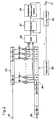
- Figure 1 shows a configuration of a speech time-scale modification apparatus according to the first embodiment of the invention.
- the speech time-scale modification apparatus includes an A/D converter 11 , a buffer 12 , a rate control circuit 13 , a demultiplexer 14 , a first memory 15 for storing an input signal having a time length T, a second memory 16 for storing an input signal having the time length T and succeeding the input signal stored in the first memory 15 , a correlator 17 for outputting a correlation function between the contents of the first memory 15 and the contents of the second memory 16 and for determining a time delay Tc at which the value of the correlation function becomes the greatest, a window function generator 18 , a first multiplier 19 , a second multiplier 20 , an adder 21 , a multiplexer 22 and a D/A converter 23 .
- an input analog signal is converted by the A/D converter 11 into a digital signal, and then written into the buffer 12 .
- the demultiplexer 14 passes the input signal stored in the buffer 12 to the first memory 15 for the duration of time length T, and then passes the input signal succeeding the contents of the first memory 15 to the second memory 16 for the duration of time length T.
- the correlator 17 calculates the correlation function by displacing timewise the contents of the first memory 15 from the contents of the second memory 16 , and determines the time delay Tc at which the value of the correlation function becomes the greatest.
- the determined time delay Tc is supplied to the rate control circuit 13 , window function generator 18 , and adder 21 .
- the window function generator 18 Based on the time delay Tc from the correlator 17 and the time-scale modification ratio ⁇ , the window function generator 18 generates a first window function whose amplitude gradually increases or decreases with time, and supplies the first window function to the first multiplier 19 .
- the window function generator 18 also generates a second window function whose amplitude is complementary to the first window function, and supplies the second window function to the second multiplier 20 .
- the first multiplier 19 multiplies the contents of the first memory 15 by the first window function from the window function generator 18
- the second multiplier 20 multiplies the contents of the second memory 16 by the second window function from the window function generator 18 .
- the adder 21 Based on the time delay Tc from the correlator 17 , the adder 21 adds the output of the first multiplier 19 and the output of the second multiplier 20 together, by shifting the latter from the former by the time delay Tc at which the value of the correlation function becomes the greatest, and supplies the resulting sum to the multiplexer 22 .
- the D/A converter 23 converts the digital signal supplied from the multiplexer 22 into an analog signal. Finally, based on the time-scale modification ratio ⁇ , the time delay Tc from the correlator 17 , and the time length T, the rate control circuit 13 determines the start position of the input signal to be passed from the buffer 12 to the first memory 15 in the next processing operation.
- the contents of the buffer 12 may be passed from the demultiplexer 14 directly to the correlator 17 , the first multiplier 19 , the second multiplier 20 , and the multiplexer 22 , respectively.
- the first memory 15 and the second memory 16 can then be eliminated.
- FIG. 2 shows a configuration of the correlator 17 in the speech time-scale modification apparatus according to the above embodiment of the invention.
- the speech time-scale modification apparatus includes an input terminal 201 for inputting the contents of the first memory 15 , an input terminal 202 for inputting the contents of the second memory 16 and an output terminal 211 .
- the speech time-scale modification apparatus further includes a memory 203 for storing the contents of the first memory 15 for the time length T, a shift register 204 having a time length of (2T - 1) for storing the contents of the second memory 16 for the time length T and for introducing a delay by every sample, multipliers 2051 - 205T , arranged in an array, for multiplying the contents of the memory 203 by the contents of the shift register 204 , an adder 206 for obtaining the total sum of the outputs of the multipliers 2051 - 205T , a comparator 207 , a correlation function maximum value memory 208 for storing the maximum value of the output of the adder 206 supplied through the comparator 207 , a delay controller 209 for controlling the time delay of the shift register 204 and a time delay memory 210 for storing the time delay of the shift register 204 at which the correlation function becomes the greatest.
- a memory 203 for storing the contents of the first memory 15 for the time length T
- the contents of the shift register 204 and the contents of the correlation function maximum value memory 208 are cleared to zero, and for the delay controller 209 and the time delay memory 210 , the time delay ⁇ is initialized to -T + 1.
- the contents of the first memory 15 is applied at the input terminal 201 and transferred to the memory 203
- the contents of the second memory 16 is applied at the input terminal 202 and transferred to the leftmost position of the shift register 204 .
- the multipliers, 2051 - 205T multiply the contents of the memory 203 by the contents of the shift register 204 .
- the adder 206 calculates the total sum of the outputs of the multipliers 2051 - 205T , and outputs the total sum as a value of a correlation function at the time delay ⁇ .
- the comparator 207 compares the output of the adder 206 with the value stored in the correlation function maximum value memory 208 . If the comparator 207 determines that the output of the adder 206 is greater than the value stored in the correlation function maximum value memory 208 , the comparator 207 supplies the output of the adder 206 to the correlation function maximum value memory 208 , and at the same time, controls the time delay memory 210 so as to store the output ⁇ from the delay controller 209 as a time delay Tc at which the value of the correlation function becomes the greatest.
- the search range of the correlation function is set at -T + 1 ⁇ ⁇ ⁇ +T -1 , but this may be set at -T + k ⁇ ⁇ ⁇ +T - j (where T > k > 1, T > j > 1). In the latter case, not only the time length of the shift register 204 can be shortened, but the number of times of correlation function calculations can also be reduced.
- the memory 203 since the memory 203 is used to store the same contents as stored in the first memory 15 , it may be configured so that the contents of the first memory 15 are input directly to the multipliers 2051 - 205T . In this case, the memory 203 can be eliminated.
- the shift register 204 since the contents to be stored in the shift register 204 are the same as the contents stored in the second memory 16 , it may be configured so that the contents of the second memory 16 are sequentially input to the multipliers 2051 - 205T each time the time delay ⁇ is changed. In this case, the shift register 204 can be eliminated.
- the first multiplier 19 and the second multiplier 20 multiply the contents of the first memory 15 and the contents of the second memory 16 with window functions whose amplitude gradually increase or decrease output from the window function generator 18 .
- the adder 21 adds the outputs of the first multiplier 19 and the second multiplier 20 together. This makes it possible to output natural a sounding speech signal with reduced occurrences of discontinuity in signal amplitude and without significant loss of data.
- the correlator 17 calculates the correlation function between the contents of the first memory 15 and the contents of the second memory 16 .
- the adder 21 adds the outputs of the first multiplier 19 and the second multiplier 20 together with a relative delay Tc at which the value of the correlation function becomes the greatest. This makes it possible to output a speech signal with high quality and with reduced occurrences of discontinuity in signal phase.
- the rate control circuit 13 controls the demultiplexer 14 and the multiplexer 22 so that the sum of the time length of the output of the adder 21 , the time length of the input signal succeeding the contents of the first memory 15 or the contents of the second memory 16 from the buffer 12 is equal to a time length determined on the basis of the time-scale modification ratio ⁇ , the time delay Tc from the correlator 17 and the time length T.
- This makes it possible to easily change the time scale modification ratio, to absorb the displacement of the time scale modification ratio which is caused by adding the outputs of the first multiplier 19 and the second multiplier 20 together with a relative delay Tc at which the value of the correlation function becomes the greatest, and to output a speech signal without significant loss of data.
- This method is intended to produce a natural sounding speech signal with reduced occurrences of discontinuity in signal amplitude and phase and without any data loss, within the range of the time-scale modification ratio ⁇ ⁇ 1.0.
- time-scale modification ratio ⁇ Reproduction time duration after time-scale modification /Reproduction time duration at normal rate .
- FIG. 3 shows a flowchart illustrating the speech time-scale modification method. The operation of this speech time-scale modification method will be described below.
- an input pointer is reset to 0.
- a first signal (XA) having a time length T is read from a position indicated by the input pointer.
- the input pointer is incremented by T.
- a second signal (XB) having the time length T is read from a position indicated by the input pointer.
- a value of the correlation function between the first signal XA and the second signal XB is calculated, and a time delay Tc at which the value of the correlation function becomes the greatest is determined.
- the first signal XA is multiplied by a window function with gradually increasing amplitude.
- the second signal XB is multiplied by a window function with gradually decreasing amplitude.
- the first signal multiplied by the window function and the second signal multiplied by the window function are added together after shifting them with a relative delay Tc at which the value of the correlation function becomes the greatest.
- the result of the addition at step 38 and a signal succeeding the first signal XA i.e. a third signal (XC) starting from a position currently indicated by the input pointer, are output for a duration of time defined by ⁇ (T - Tc)/( ⁇ - 1) .
- the input pointer is incremented by (2T - ⁇ T - Tc) /( ⁇ - 1) .
- the process returns to step 32 .
- Figure 4 shows the flowchart detailing the processing at step 35 in Figure 3 , at which the correlation function between the first signal XA and the second signal XB is calculated and a time delay Tc at which the value of the correlation function becomes the greatest is determined.
- step 401 the time delay ⁇ , the time delay Tc at which the value of the correlation function becomes the greatest, and the maximum value Rmax of the correlation function are respectively initialized to zero.
- step 404 the value of the correlation function R( ⁇ ) between the first signal XA and the second signal XB, when the time delay ⁇ is not negative, is calculated, in accordance with the following equation.
- step 405 if the value of the correlation function R( ⁇ ) obtained at step 404 is not greater than the maximum value Rmax of the correlation function which is previously obtained, the process branches to step 408 . Otherwise, the process proceeds to step 406 , at which the maximum value Rmax of the correlation function is updated by R( ⁇ ), and at step 407 , the time delay Tc at which the value of the correlation function becomes the greatest is updated by ⁇ .
- step 408 the time delay ⁇ is incremented by 1.
- step 409 if the time delay ⁇ is not greater than a predetermined value ⁇ max+, the process returns to step 404 .
- the processing steps 404 to 408 are repeated until the time delay ⁇ becomes equal to the predetermined value ⁇ max+.
- step 410 the time delay ⁇ is initialized to -1.
- step 411 the value of the correlation function R( ⁇ ) between the first signal XA and the second signal XB, when the time delay ⁇ is negative, is calculated, in accordance with the following equation. where ⁇ max- ⁇ ⁇ ⁇ 0.
- step 412 if the value of the correlation function R( ⁇ ) obtained at step 411 is not greater than the maximum value Rmax of the correlation function which is previously obtained, the process branches to step 415 .
- step 413 at which the maximum value Rmax of the correlation function is updated to be R( ⁇ )
- step 414 the time delay Tc at which the value of the correlation function becomes the greatest is updated to be ⁇ .
- step 415 the time delay ⁇ is decremented by 1.
- step 416 if the time delay ⁇ is not smaller than a predetermined value ⁇ max-, the process returns to step 411 .
- the processing steps 411 to 415 are repeated until the time delay ⁇ becomes equal to the predetermined value ⁇ max-.
- step 417 the time delay Tc at which the value of the correlation function becomes the greatest is output.
- Figures 5A to 5C show schematic diagrams for describing the processing steps 36 , 37 , and 38 shown in Figure 3 .
- Figure 5B shows the case in which the time delay Tc at which the value of the correlation function becomes the greatest is greater than 0 (Tc > 0).
- Figure 5C shows the case in which the time delay Tc at which the value of the correlation function becomes the greatest is smaller than 0 (Tc ⁇ 0).
- the first signal is multiplied by a first window function whose amplitude gradually increases with time
- the second signal is multiplied by a second window function whose amplitude gradually decreases with time
- the first signal multiplied by the first window function and the second signal multiplied by the second window function are added together after displacing them by the time delay Tc at which the correlation function becomes the greatest.
- the shape of the window function is varied in accordance with the time delay Tc at which the correlation function becomes the greatest.
- Tc the first window function monotonically increases from 0 to 1 during the time length T
- the second window function monotonically decreases from 1 to 0 in a manner complementary to the first window function during the time length T.
- Tc > the first window function has a value of 0 during the time length Tc and then monotonically increases from 0 to 1 during the time length (T - Tc)
- the second window function monotonically decreases from 1 to 0 in a manner complementary to the first window function during the time length (T - Tc) and then has a value of 0 during the time length Tc.
- the first window function monotonically increases from 0 to 1 during the time length (T - (-Tc)) and then has a value of 1 during the time length (-Tc), whereas the second window function has a value of 1 during the time length (-Tc) and then monotonically decreases from 1 to 0 in a manner complementary to the first window function during the time length (T - (-Tc)).
- the length of the resulting sum is given as T - Tc.
- FIGS 6A and 6B schematically show an example of an input signal and an output signal which are processed in accordance with the speech time-scale modification method mentioned above.
- Figure 6A shows an input signal
- the sum of the time length of the added signal and the third signal is determined on the basis of the time-scale modification ratio ⁇ , the time delay Tcn at which the value of the correlation function becomes the greatest, and the time length T.
- the first signal XA is multiplied by the first window function having a gradually increasing amplitude and the second signal XB is multiplied by the second window function having a gradually decreasing amplitude. Then, the first signal XA multiplied by the first window function and the second signal XB multiplied by the second window function are added together. This makes it possible to reduce the discontinuity of the added signal in amplitude.
- first signal XA multiplied by the first window function and the second signal XB multiplied by the second window function are added together with a relative delay Tc at which the value of the correlation function becomes the greatest. This makes it possible to reduce the discontinuity in signal phase.
- a signal obtained by adding the first signal XA multiplied by the first window function to the second signal XB multiplied by the second window function and a third signal XC succeeding the first signal XA are output for a duration of time determined on the basis of the time-scale modification ratio ⁇ , the time delay Tc at which the value of the correlation function becomes the greatest and the time length T.
- This method is intended to produce a natural sounding speech signal with reduced occurrences of discontinuity in signal amplitude and phase and without any data loss, within the range of the time-scale modification ratio ⁇ ⁇ 1.0.
- Figure 7 shows the flowchart illustrating the speech time-scale modification method according to the second embodiment of the invention.
- an input pointer is reset to 0.
- a first signal (XA) having a time length T is read from a position indicated by the input pointer.
- the input pointer is incremented by T.
- a second signal (XB) having the time length T is read from a position indicated by the input pointer.
- a value of the correlation function between the first signal XA and the second signal XB is calculated, and a time delay Tc at which the value of the correlation function becomes the greatest is determined.
- the first signal XA is multiplied by a first window function having a gradually decreasing amplitude.
- the second signal XB is multiplied by a second window function having a gradually increasing amplitude.
- the first signal multiplied by the first window function and the second signal multiplied by the second window function are added together after shifting them to the position of the time delay Tc at which the value of the correlation function becomes the greatest.
- the input pointer is incremented by T.
- the result of the addition at step 78 and a signal succeeding the second signal XB i.e. a third signal (XC) starting from a position currently indicated by the input pointer, are output for a duration of time defined by ⁇ (T - Tc)/(1 - ⁇ ) .
- the input pointer is incremented by (2 ⁇ T - T - Tc)/(1 - ⁇ ) .
- the process returns to step 72 .
- step 75 in Figure 7 at which the value of the correlation function between the first signal XA and the second signal XB is calculated and a time delay Tc at which the value of the correlation function becomes the greatest is determined, is the same as illustrated in Figure 4 .
- Figures 8A to 8C show schematic diagrams for describing the processing steps 76 , 77 , and 78 shown in Figure 7 .
- Figure 8B shows the case in which the time delay Tc at which the value of the correlation function becomes the greatest is greater than 0 (Tc > 0).
- Figure 8C shows the case in which the time delay Tc at which the value of the correlation function becomes the greatest is smaller than 0 (Tc ⁇ 0).
- the first signal is multiplied by the first window function whose amplitude gradually decreases with time
- the second signal is multiplied by the second window function whose amplitude gradually increases with time
- the results are added together after displacing them by the time delay Tc at which the correlation function becomes the greatest.
- the shape of the window function is varied in accordance with the time delay Tc at which the correlation function becomes the greatest. The time length of the resulting sum is given as T + Tc.
- FIGS 9A and 9B schematically show an example of an input signal and an output signal which are processed by the speech time-scale modification method mentioned above.
- Figure 9A shows an input signal
- the sum of the time length of a signal obtained by adding the first signal XAn to the second signal XBn and the time length of a third signal XCn succeeding the second signal XBn is equal to a time length defined by ⁇ (T - Tcn)/(1 - ⁇ ) .
- the sum of the time length of the added signal and the third signal is determined on the basis of the time-scale modification ratio ⁇ , the time delay Tcn at which the value of the correlation function becomes the greatest, and the time length T.
- the first signal XA is multiplied by the first window function having a gradually decreasing amplitude and the second signal XB is multiplied by the second window function having a gradually increasing amplitude. Then, the first signal XA multiplied by the first window function and the second signal XB multiplied by the second window function are added together. This makes it possible to reduce the discontinuity of the added signal in amplitude.
- first signal XA multiplied by the first window function and the second signal XB multiplied by the second window function are added together with a relative delay Tc at which the value of the correlation function becomes the greatest. This makes it possible to reduce the discontinuity in signal phase.
- a signal obtained by adding the first signal XA multiplied by the first window function to the second signal XB multiplied by the second window function and a third signal XC succeeding the second signal XB are output for a duration of time determined on the basis of the time-scale modification ratio ⁇ , the time delay Tc at which the value of the correlation function becomes the greatest and the time length T.
- the present invention is intended to provide a speech time-scale modification apparatus and method that can be realized with simple hardware and that is capable of producing natural sounding speech with reduced occurrences of discontinuity in signal amplitude and phase and without significant loss of data.
- Figure 10 shows a configuration of a speech time-scale modification apparatus according to the second embodiment of the invention.
- the speech time-scale modification apparatus includes an A/D converter 11 , a buffer 12 , a rate control circuit 13 , a demultiplexer 14 , a first memory 15 for storing an input signal having a time length (2T - 1), a second memory 16 for storing an input signal having the time length (2T - 1) and being delayed by time T from the input signal stored in the first memory 15 , a correlator 17 for calculating a value of the correlation function between the contents of the first memory 15 and the contents of the second memory 16 and for determining a time delay Tc at which the value of the correlation function becomes the greatest, a window function generator 18 , a first multiplier 19 , a second multiplier 20 , an adder 21 , a multiplexer 22 , a D/A converter 23 and a memory read control circuit 24 for reading a signal from the contents of the first memory 15 in accordance with
- an input analog signal is converted by the A/D converter 11 into a digital signal, and then written into the buffer 12 .
- the demultiplexer 14 passes the input signal stored in the buffer 12 to the first memory 15 for the duration of time length (2T - 1), and then passes the input signal delaying by time T from the input signal stored in the first memory 15 to the second memory 16 for the duration of time length (2T - 1).
- the correlator 17 calculates a value of the correlation function by displacing timewise the contents of the first memory 15 from the contents of the second memory 16 , and determines a time delay Tc at which the value of the correlation function becomes the greatest.
- the determined time delay Tc is supplied to the rate control circuit 13 , the window function generator 18 , the memory read control circuit 24 , and the adder 21 .
- the memory read control circuit 24 reads a signal having a time length T or a time length (T +
- time length
- indicates an absolute value operation.
- the window function generator 18 Based on the time delay Tc from the correlator 17 and the time-scale modification ratio ⁇ , the window function generator 18 generates a first window function whose amplitude gradually increases or decreases with time and whose time length is T +
- the window function generator 18 also supplies a second window function, whose amplitude is complementary to the first window function and whose time length is T or (T +
- the first multiplier 19 multiplies the output of the first memory 15 by the first window function from the window function generator 18
- the adder 21 Based on the time delay Tc from the correlator 17 , the adder 21 adds the output of the first multiplier 19 and the output of the second multiplier 20 together, with shifting the latter from the former by the time delay Tc at which the value of the correlation function becomes the greatest and with overlapping one with the other for the time length T, and supplies the resulting sum to the multiplexer 22 .
- the D/A converter 23 converts the digital signal supplied from the multiplexer 22 into an analog signal. Finally, based on the time-scale modification ratio ⁇ , the time delay Tc from the correlator 17 , and the time length T, the rate control circuit 13 determines the start position of the input signal to be passed from the buffer 12 to the first memory 15 in the next processing operation.
- the contents of the buffer 12 may be passed from the demultiplexer 14 directly to the correlator 17 , the first multiplier 19 , the second multiplier 20 , and the multiplexer 22 , respectively.
- the first memory 15 and the second memory 16 can then be eliminated.
- FIG 11 shows the configuration of the correlator 17 in the speech time-scale modification apparatus according to the second embodiment of the invention.
- the correlator 17 includes an input terminal 201 for inputting the contents of the first memory 15 , an input terminal 202 for inputting the contents of the second memory 16 , and an output terminal 211 .
- the correlator further includes a first shift register 212 having a time length (3T - 2) for storing the contents of the first memory 15 for the time length (2T - 1) and for introducing a delay by one sample, a second shift register 213 having the time length (3T - 2) for storing the contents of the second memory 16 for the time length (2T - 1) and for introducing a delay by one sample, multipliers 2051 - 205T , arranged in an array, for multiplying the contents of the first shift register 212 by the contents of the second shift register 213 , an adder 206 for obtaining the total sum of the outputs of the multipliers 2051 - 205T , a comparator 207 , a correlation function maximum value memory 208 for storing the maximum value of the output of the adder 206 supplied through the comparator 207 , a delay controller 209 for controlling the time delay of the first shift register 212 and second shift register 213 , a time delay memory 210 for storing the time delay of the first shift register
- the contents of the first shift register 212 , the contents of the second shift register 213 , the content of the correlation function maximum value memory 208 , the content of the delay controller 209 and the content of the time delay memory 210 are cleared to zero.
- the contents of the first memory 15 is applied at the input terminal 201 and transferred to the leftmost position of the first shift register 212 for the duration of time length (2T - 1), while the contents of the second memory 202 is applied at the input terminal 202 and transferred to the leftmost position of the second shift register 213 for the duration of time length (2T - 1).
- the multipliers 2051 - 205T multiply the contents of the first shift register 212 by the contents of the second shift register 213 .
- the adder 206 obtains the total sum of the outputs of the multipliers 2051 - 205T , and outputs the sum as a value of the correlation function when the time delay is ⁇ .
- the comparator 207 compares the output of the adder 206 with the content of the correlation function maximum value memory 208 . If the comparator 207 judges that the output of the adder 206 is greater than the value stored in the correlation function maximum value memory 208 , the comparator 207 supplies the output of the adder 206 to the correlation function maximum value memory 208 , and at the same time, controls the time delay memory 210 so as to store the output ⁇ of the delay controller 209 as a time delay Tc at which the value of the correlation function becomes the greatest.
- the delay controller 209 controls the first and second shift register 212 and 213 so that the contents of the second memory 16 are fixed at the leftmost position of the second shift register 213 , so that the contents of the first shift register 212 are delayed to the right direction by one sample at a time, and so that the time delay ⁇ , initialized to 0, is incremented by 1 at a time.
- the delay controller 209 controls the first and second shift registers 212 and 213 so that the contents of the first memory 15 are fixed at the leftmost position of the first shift register 212 , so that the contents of the second shift register 213 are delayed to the right direction by one sample at a time, and so that the time delay ⁇ , initialized to 0, is decremented by 1 at a time. Then, the process returns to the step where the multipliers, 2051 - 205T , multiply the contents of the first shift register 212 by the contents of the second shift register 213 . This process is repeated as long as the time delay ⁇ stays within the range of -T + 1 ⁇ ⁇ ⁇ +T -1 . When these repetitions are completed, the contents stored in the time delay memory 210 is output from the output terminal 211 as a time delay Tc at which the value of the correlation function between the contents of the first memory 15 and the contents of the second memory 16 becomes the greatest.
- the search range of the correlation function is set at -T + 1 ⁇ ⁇ ⁇ +T -1 , but this may be set at -T + k ⁇ ⁇ ⁇ +T - j (where T > k > 1, T > j > 1).
- T > k > 1, T > j > 1 the search range of the correlation function is set at -T + 1 ⁇ ⁇ ⁇ +T -1 , but this may be set at -T + k ⁇ ⁇ ⁇ +T - j (where T > k > 1, T > j > 1).
- the contents to be stored in the first shift register 212 are the same as the contents stored in the first memory 15
- the contents to be stored in the second shift register 213 are the same as the contents stored in the second memory 16
- the first shift register 212 and the second shift register 213 can be eliminated.
- the first multiplier 19 and the second multiplier 20 multiply the contents of the first memory 15 and the contents of the second memory 16 with window functions whose amplitude gradually increase or decrease output from the window function generator 18 .
- the adder 21 adds the outputs of the first multiplier 19 and the second multiplier 20 together. This makes it possible to output a natural sounding speech signal with reduced occurrences of discontinuity in signal amplitude and without significant loss of data.
- the correlator 17 calculates the correlation function between the contents of the first memory 15 and the contents of the second memory 16 .
- the adder 21 adds the outputs of the first multiplier 19 and the second multiplier 20 together with a relative delay Tc at which the value of the correlation function becomes the greatest. This makes it possible to output a speech signal with high quality and with reduced occurrences of discontinuity in signal phase.
- the rate control circuit 13 controls the demultiplexer 14 and the multiplexer 22 so that the sum of the time length of the output of the adder 21 , the time length of input signal succeeding the contents of the first memory 15 or the contents of the second memory 16 from the buffer 12 is equal to a time length determined on the basis of the time-scale modification ratio ⁇ , the time delay Tc from the correlator 17 and the time length T.
- This makes it possible to easily change the time scale modification ratio, to absorb the displacement of the time scale modification ratio which is caused by adding the outputs of the first multiplier 19 and the second multiplier 20 together with a relative delay Tc at which the value of the correlation function becomes the greatest, and to output a speech signal without significant loss of data.
- the adder 21 adds the contents of the first memory 15 which have a time length T or T +
- the correlator 17 calculates the value of the correlation function by overlapping the contents of the first memory 15 with the contents of the second memory 16 for the time length T regardless of the time delay ⁇ . Therefore, the time length during which the correlation function is calculated does not become shorter with increasing departure of the time delay ⁇ from 0, so that the correlation function can be calculated with good accuracy.
- the speech time-scale modification method can be applied when the time-scale modification ratio ⁇ is within the range defined by the following expression. (T + ⁇ max+)/(2T) ⁇ ⁇ ⁇ 1.0
- Figure 12 shows the flowchart illustrating the speech time-scale modification method. The operation will be described below.
- an address ip1 indicated by the input data pointer P1 is set to a starting address of an input signal to be reproduced.
- an address ip2 indicated by the pointer P2 is set to an address away from the address indicated by the input data pointer P1 by T.
- an address op indicated by the output data pointer is set to an initial value.
- the time-scale modification ratio ⁇ is set. The ratio ⁇ should satisfy the condition set by the above expression.
- a signal A has a time length T from the pointer P1 and a signal B has the time length T from the pointer P2.
- a value of the correlation function between the signal A and a signal which has the time length T and delays from the signal B by a time delay (- ⁇ ) for -T ⁇ ⁇ ⁇ 0 is calculated, and a value of the correlation function between the signal B and a signal which has the time length T and delays from the signal A by the time delay ⁇ for 0 ⁇ ⁇ ⁇ T is calculated.
- a time delay Tc at which the value of the correlation function becomes the greatest is determined.
- the time delay ⁇ is negative
- the signal A is fixed as the reference
- a signal B' x(ip2 - ⁇ + m) (where 0 ⁇ m ⁇ T - 1) delaying by time - ⁇ from the signal B is used, as shown in step 1303 of Figure 13 .
- a positive maximum value ⁇ max+ of the time delay ⁇ and a negative maximum value ⁇ max- of the time delay ⁇ are predetermined, to limit the range of the time delay ⁇ based on which the correlation function is to be calculated.
- the time delay Tc at which the value of the correlation function becomes the greatest can thus be obtained.
- a time length Tt, during which the input signal is outputted directly is calculated as shown in Figure 14 .
- the calculation formula is different according to the sign of the time delay Tc. More specifically, when the time delay Tc at which the value of the correlation function becomes the greatest is positive, the time length Tt during which the input signal is to be outputed directly is obtained as shown in step 1403 of Figure 14 . On the other hand, when the time delay Tc at which the value of the correlation function becomes the greatest is negative, the time length Tt during which the input signal is to be output directly is obtained as shown in step 1402 of Figure 14 .
- Wdec(i) shown in steps 1208 and 1210 is a window function wherein the size of the window is 1 when i is 0, the size decreasing monotonically in linear fashion as i increases and reaching 0 when i is T - 1.
- Winc(i) shown in steps 1208 and 1210 is a window function wherein the size of the window is 0 when i is 0, the size increasing monotonically in linear fashion as i increases and reaching 1 when i is T - 1.
- Figure 15 shows how the output signal is obtained in cases where the value of the time delay Tc at which the value of the correlation function becomes the greatest is zero, where Tc is positive, and where Tc is negative. It can be seen that when the time delay Tc at which the value of the correlation function becomes the greatest is positive, Tt is shorter than when Tc is zero. Conversely, when Tc is negative, Tt is longer. This is because the length of Tt is adjusted according to the displacement of Tc in order to prevent the occurrence of a departure from the preset time-scale modification ratio.
- a method of compressing the reproduction time for output (a method of increasing the reproduction speed without changing the pitch of speech) can be realized which has the features hereinafter described.
- a value of the correlation function is calculated using the pointer P1 or P2 as the reference, and at step 1208 or 1210 , the signal A or signal A' and the signal B' or signal B are weighted with the time delay Tc at which the value of the correlation function becomes the greatest, and then added together. This prevents a significant phase mismatch from occurring between the segments where the signals are connected together.
- the signal A or A' is multiplied by the window function Wdec(i) whose amplitude monotonically decreases with time
- the signal B' or signal B is multiplied by the window function Winc(i) whose amplitude monotonically increases with time.
- the time length Tt during which the input signal succeeding the signal B' or signal B is directly output after the weight addition is calculated on the basis of the time delay Tc at which the value of the correlation function becomes the greatest, so that a change in Tc does not cause a displacement of the time-scale modification ratio ⁇ of the actual output signal.
- the length of the segment along which the addition with weights is performed at step 1208 or 1210 is fixed to a constant time length T which is independent of the input signal or the time delay Tc at which the value of the correction function becomes the greatest, so that there is no possibility of the cross-fade length being reduced because of the value of Tc.
- the resulting reproduction sound is thus characterized by smooth low-frequency components contained in the signals connected together.
- the speech time-scale modification method can be applied when the time-scale modification ratio ⁇ is within the range defined by the following expression. 1.0 ⁇ ⁇ ⁇ T/ ⁇ max+
- Figure 16 shows the flowchart illustrating the speech time-scale modification method. The operation will be described below.
- an address ip1 indicated by the input data pointer P1 is set to a starting address of an input signal to be reproduced.
- an address ip2 indicated by the pointer P2 is set to an address away from the address indicated by the input data pointer P1 by T.
- an address op indicated by the output data pointer is set to an initial value.
- the time-scale modification ratio ⁇ is set. The ratio ⁇ should satisfy the condition set by the above expression.
- a signal A has a time length T from the pointer P1 and a signal B has the time length T from the pointer P2.
- a value of the correlation function between the signal A and a signal which has the time length T and delays from the signal B by a time delay (- ⁇ ) for -T ⁇ ⁇ ⁇ 0 is calculated, and a value of the correlation function between the signal B and a signal which has the time length T and delays from the signal A by the time delay ⁇ for 0 ⁇ ⁇ ⁇ T is calculated.
- a time delay Tc at which the value of the correlation function becomes the greatest is determined.
- the value of the correlation function COR is calculated in the following manner.
- a maximum value ⁇ max+ of the time delay ⁇ and a minimum value ⁇ max- of the time delay ⁇ are predetermined, to limit the range of the time delay ⁇ based on which the correlation function is to be calculated.
- the time delay Tc at which the value of the correlation function becomes the greatest can thus be obtained.
- a time length Tt, during which the input signal is output directly is calculated as shown in Figure 17 .
- the calculation formula is different according to the sign of Tc. More specifically, when the time delay Tc at which the value of the correlation function becomes the greatest is positive, the time length Tt during which the input signal is to be output directly is obtained as shown in step 1703 . On the other hand, when the time delay Tc at which the correlation function becomes the greatest is negative, the time length Tt during which the input signal is to be output directly is obtained as shown in step 1702 .
- Wdec(i) shown in steps 1608 and 1610 is a window function wherein the size of the window is 1 when i is 0, the size decreasing monotonically in linear fashion as i increases and reaching 0 when i is T - 1.
- Winc(i) shown in steps 1608 and 1610 is a window function wherein the size of the window is 0 when i is 0, the size increasing monotonically in linear fashion as i increases and reaching 1 when i is T - 1.
- Figure 18 shows how the output signal is obtained in cases where the value of the time delay Tc at which the value of the correlation function becomes the greatest is zero, where Tc is positive, and where Tc is negative. It can be seen that when the time delay Tc is positive, Tt is shorter than when Tc is zero. Conversely, when Tc is negative, Tt is longer. This is because the length of Tt is adjusted according to the displacement of Tc in order to prevent the occurrence of a departure from the preset time-scale modification ratio ⁇ .
- the addresses indicated by the input data pointers and output data pointer are updated as shown in step 1613 , and then, the process starting with step 1602 is repeated.
- a method of expanding the reproduction time (a method of reducing the reproduction speed without changing the pitch of speech) can be realized which has the features hereinafter described.
- a value of the correlation function is calculated using the pointer P1 or P2 as the reference, and at step 1608 or 1610 , the signal A or signal A' and the signal B' or signal B are weighted with the time delay Tc at which the value of the correlation function becomes the greatest, and then added together. This prevents a significant phase mismatch from occurring between the segments where the signals are connected together.
- the signal B' or B is multiplied by the window function Wdec(i) whose amplitude monotonically deceases with time, and the signal A or signal A' is multiplied by the window function Winc(i) whose amplitude monotonically increases with time. This ensures a good amplitude continuity between the segments where the signals are connected together.
- the time length Tt during which the input signal succeeding the signal A or signal A' is directly output after the weight addition is calculated on the basis of the time delay Tc at which the value of the correlation function becomes the greatest, so that a change in Tc does not cause a displacement of the time-scale modification ratio ⁇ of the actual output signal.
- the length of the segment along which the weight addition is performed at step 1608 or 1610 is fixed to a constant length T which is independent of the input signal or the time delay Tc, so that there is no possibility of the cross-fade length being reduced because of the value of Tc.
- the resulting reproduction sound is thus characterized by smooth low-frequency components contained in the signals connected together.
Applications Claiming Priority (6)
| Application Number | Priority Date | Filing Date | Title |
|---|---|---|---|
| JP973793 | 1993-01-25 | ||
| JP00973793A JP3147562B2 (ja) | 1993-01-25 | 1993-01-25 | 音声速度変換方法 |
| JP9737/93 | 1993-01-25 | ||
| JP14922493A JP3156020B2 (ja) | 1993-06-21 | 1993-06-21 | 音声速度変換方法 |
| JP14922493 | 1993-06-21 | ||
| JP149224/93 | 1993-06-21 |
Publications (3)
| Publication Number | Publication Date |
|---|---|
| EP0608833A2 true EP0608833A2 (de) | 1994-08-03 |
| EP0608833A3 EP0608833A3 (de) | 1995-01-25 |
| EP0608833B1 EP0608833B1 (de) | 2001-10-17 |
Family
ID=26344518
Family Applications (1)
| Application Number | Title | Priority Date | Filing Date |
|---|---|---|---|
| EP94101057A Expired - Lifetime EP0608833B1 (de) | 1993-01-25 | 1994-01-25 | Verfahren und Vorrichtung zur Durchführung einer Zeitskalenmodifikation von Sprachsignalen |
Country Status (3)
| Country | Link |
|---|---|
| US (1) | US5630013A (de) |
| EP (1) | EP0608833B1 (de) |
| DE (1) | DE69428612T2 (de) |
Cited By (12)
| Publication number | Priority date | Publication date | Assignee | Title |
|---|---|---|---|---|
| EP0865026A2 (de) * | 1997-03-14 | 1998-09-16 | GRUNDIG Aktiengesellschaft | Effizientes Verfahren zur Geschwindigkeitsmodifikation von Sprachsignalen |
| EP0883106A1 (de) * | 1996-11-11 | 1998-12-09 | Matsushita Electric Industrial Co., Ltd. | Tonwiedergabe-geschwindigkeitsumwandler |
| EP0910065A1 (de) * | 1997-03-14 | 1999-04-21 | Nippon Hoso Kyokai | Sprachschnellheitsveränderungsverfahren und vorrichtung |
| WO2005034091A1 (de) * | 2003-09-30 | 2005-04-14 | Siemens Aktiengesellschaft | Verfahren und anordnung zur audioübertragung |
| EP1501075A3 (de) * | 1998-11-13 | 2007-08-22 | Lernout & Hauspie Speech Products N.V. | Sprachsynthese mittels Verknüpfung von Sprachwellenformen |
| US7283954B2 (en) | 2001-04-13 | 2007-10-16 | Dolby Laboratories Licensing Corporation | Comparing audio using characterizations based on auditory events |
| US7313519B2 (en) | 2001-05-10 | 2007-12-25 | Dolby Laboratories Licensing Corporation | Transient performance of low bit rate audio coding systems by reducing pre-noise |
| US7461002B2 (en) | 2001-04-13 | 2008-12-02 | Dolby Laboratories Licensing Corporation | Method for time aligning audio signals using characterizations based on auditory events |
| US7610205B2 (en) | 2002-02-12 | 2009-10-27 | Dolby Laboratories Licensing Corporation | High quality time-scaling and pitch-scaling of audio signals |
| US7711123B2 (en) | 2001-04-13 | 2010-05-04 | Dolby Laboratories Licensing Corporation | Segmenting audio signals into auditory events |
| US7974837B2 (en) | 2005-06-23 | 2011-07-05 | Panasonic Corporation | Audio encoding apparatus, audio decoding apparatus, and audio encoded information transmitting apparatus |
| CN102117613B (zh) * | 2009-12-31 | 2012-12-12 | 展讯通信(上海)有限公司 | 数字音频变速处理方法及其设备 |
Families Citing this family (30)
| Publication number | Priority date | Publication date | Assignee | Title |
|---|---|---|---|---|
| DE4227826C2 (de) * | 1991-08-23 | 1999-07-22 | Hitachi Ltd | Digitales Verarbeitungsgerät für akustische Signale |
| JP2976860B2 (ja) * | 1995-09-13 | 1999-11-10 | 松下電器産業株式会社 | 再生装置 |
| KR100251497B1 (ko) * | 1995-09-30 | 2000-06-01 | 윤종용 | 음성신호 변속재생방법 및 그 장치 |
| JPH09198089A (ja) * | 1996-01-19 | 1997-07-31 | Matsushita Electric Ind Co Ltd | 再生速度変換装置 |
| US5806023A (en) * | 1996-02-23 | 1998-09-08 | Motorola, Inc. | Method and apparatus for time-scale modification of a signal |
| JP3266819B2 (ja) * | 1996-07-30 | 2002-03-18 | 株式会社エイ・ティ・アール人間情報通信研究所 | 周期信号変換方法、音変換方法および信号分析方法 |
| US5751901A (en) * | 1996-07-31 | 1998-05-12 | Qualcomm Incorporated | Method for searching an excitation codebook in a code excited linear prediction (CELP) coder |
| US6049766A (en) * | 1996-11-07 | 2000-04-11 | Creative Technology Ltd. | Time-domain time/pitch scaling of speech or audio signals with transient handling |
| JP3017715B2 (ja) * | 1997-10-31 | 2000-03-13 | 松下電器産業株式会社 | 音声再生装置 |
| US6182042B1 (en) | 1998-07-07 | 2001-01-30 | Creative Technology Ltd. | Sound modification employing spectral warping techniques |
| US6374225B1 (en) * | 1998-10-09 | 2002-04-16 | Enounce, Incorporated | Method and apparatus to prepare listener-interest-filtered works |
| DE69925932T2 (de) | 1998-11-13 | 2006-05-11 | Lernout & Hauspie Speech Products N.V. | Sprachsynthese durch verkettung von sprachwellenformen |
| US6625655B2 (en) * | 1999-05-04 | 2003-09-23 | Enounce, Incorporated | Method and apparatus for providing continuous playback or distribution of audio and audio-visual streamed multimedia reveived over networks having non-deterministic delays |
| US6625656B2 (en) * | 1999-05-04 | 2003-09-23 | Enounce, Incorporated | Method and apparatus for continuous playback or distribution of information including audio-visual streamed multimedia |
| AU4200600A (en) * | 1999-09-16 | 2001-04-17 | Enounce, Incorporated | Method and apparatus to determine and use audience affinity and aptitude |
| US6718309B1 (en) | 2000-07-26 | 2004-04-06 | Ssi Corporation | Continuously variable time scale modification of digital audio signals |
| FR2820227B1 (fr) * | 2001-01-30 | 2003-04-18 | France Telecom | Procede et dispositif de reduction de bruit |
| US7366659B2 (en) * | 2002-06-07 | 2008-04-29 | Lucent Technologies Inc. | Methods and devices for selectively generating time-scaled sound signals |
| US7426470B2 (en) * | 2002-10-03 | 2008-09-16 | Ntt Docomo, Inc. | Energy-based nonuniform time-scale modification of audio signals |
| US6999922B2 (en) * | 2003-06-27 | 2006-02-14 | Motorola, Inc. | Synchronization and overlap method and system for single buffer speech compression and expansion |
| US8340972B2 (en) * | 2003-06-27 | 2012-12-25 | Motorola Mobility Llc | Psychoacoustic method and system to impose a preferred talking rate through auditory feedback rate adjustment |
| AU2005207606B2 (en) * | 2004-01-16 | 2010-11-11 | Nuance Communications, Inc. | Corpus-based speech synthesis based on segment recombination |
| US7676362B2 (en) * | 2004-12-31 | 2010-03-09 | Motorola, Inc. | Method and apparatus for enhancing loudness of a speech signal |
| US8280730B2 (en) | 2005-05-25 | 2012-10-02 | Motorola Mobility Llc | Method and apparatus of increasing speech intelligibility in noisy environments |
| WO2007086365A1 (ja) * | 2006-01-24 | 2007-08-02 | Matsushita Electric Industrial Co., Ltd. | 変換装置 |
| US8027377B2 (en) * | 2006-08-14 | 2011-09-27 | Intersil Americas Inc. | Differential driver with common-mode voltage tracking and method |
| US8321222B2 (en) * | 2007-08-14 | 2012-11-27 | Nuance Communications, Inc. | Synthesis by generation and concatenation of multi-form segments |
| TWI365442B (en) * | 2008-04-09 | 2012-06-01 | Realtek Semiconductor Corp | Audio signal processing method |
| US20100263005A1 (en) * | 2009-04-08 | 2010-10-14 | Eric Foster White | Method and system for egnaging interactive web content |
| US20140013268A1 (en) * | 2012-07-09 | 2014-01-09 | Mobitude, LLC, a Delaware LLC | Method for creating a scripted exchange |
Citations (2)
| Publication number | Priority date | Publication date | Assignee | Title |
|---|---|---|---|---|
| US4864620A (en) * | 1987-12-21 | 1989-09-05 | The Dsp Group, Inc. | Method for performing time-scale modification of speech information or speech signals |
| EP0427953A2 (de) * | 1989-10-06 | 1991-05-22 | Matsushita Electric Industrial Co., Ltd. | Einrichtung und Methode zur Veränderung von Sprechgeschwindigkeit |
Family Cites Families (5)
| Publication number | Priority date | Publication date | Assignee | Title |
|---|---|---|---|---|
| US3786195A (en) * | 1971-08-13 | 1974-01-15 | Dc Dt Liquidating Partnership | Variable delay line signal processor for sound reproduction |
| US4246617A (en) * | 1979-07-30 | 1981-01-20 | Massachusetts Institute Of Technology | Digital system for changing the rate of recorded speech |
| US4464784A (en) * | 1981-04-30 | 1984-08-07 | Eventide Clockworks, Inc. | Pitch changer with glitch minimizer |
| US4722009A (en) * | 1985-04-02 | 1988-01-26 | Matsushita Electric Industrial Co., Ltd. | Tone restoring apparatus |
| US5175769A (en) * | 1991-07-23 | 1992-12-29 | Rolm Systems | Method for time-scale modification of signals |
-
1994
- 1994-01-25 DE DE69428612T patent/DE69428612T2/de not_active Expired - Fee Related
- 1994-01-25 EP EP94101057A patent/EP0608833B1/de not_active Expired - Lifetime
- 1994-01-25 US US08/187,295 patent/US5630013A/en not_active Expired - Lifetime
Patent Citations (2)
| Publication number | Priority date | Publication date | Assignee | Title |
|---|---|---|---|---|
| US4864620A (en) * | 1987-12-21 | 1989-09-05 | The Dsp Group, Inc. | Method for performing time-scale modification of speech information or speech signals |
| EP0427953A2 (de) * | 1989-10-06 | 1991-05-22 | Matsushita Electric Industrial Co., Ltd. | Einrichtung und Methode zur Veränderung von Sprechgeschwindigkeit |
Non-Patent Citations (1)
| Title |
|---|
| INTERNATIONAL CONFERENCE ON CONSUMER ELECTRONICS 92, 2 June 1992, ROSEMONT, IL, US pages 166 - 167 SUZUKI ET AL. 'Time-scale modification of speech signals using cross-correlation' * |
Cited By (18)
| Publication number | Priority date | Publication date | Assignee | Title |
|---|---|---|---|---|
| EP0883106A1 (de) * | 1996-11-11 | 1998-12-09 | Matsushita Electric Industrial Co., Ltd. | Tonwiedergabe-geschwindigkeitsumwandler |
| EP0883106A4 (de) * | 1996-11-11 | 2000-02-23 | Matsushita Electric Ind Co Ltd | Tonwiedergabe-geschwindigkeitsumwandler |
| US6115687A (en) * | 1996-11-11 | 2000-09-05 | Matsushita Electric Industrial Co., Ltd. | Sound reproducing speed converter |
| EP0865026A2 (de) * | 1997-03-14 | 1998-09-16 | GRUNDIG Aktiengesellschaft | Effizientes Verfahren zur Geschwindigkeitsmodifikation von Sprachsignalen |
| EP0865026A3 (de) * | 1997-03-14 | 1999-02-10 | GRUNDIG Aktiengesellschaft | Effizientes Verfahren zur Geschwindigkeitsmodifikation von Sprachsignalen |
| EP0910065A1 (de) * | 1997-03-14 | 1999-04-21 | Nippon Hoso Kyokai | Sprachschnellheitsveränderungsverfahren und vorrichtung |
| EP0910065B1 (de) * | 1997-03-14 | 2003-07-09 | Nippon Hoso Kyokai | Sprachschnellheitsveränderungsverfahren und vorrichtung |
| EP1501075A3 (de) * | 1998-11-13 | 2007-08-22 | Lernout & Hauspie Speech Products N.V. | Sprachsynthese mittels Verknüpfung von Sprachwellenformen |
| US7283954B2 (en) | 2001-04-13 | 2007-10-16 | Dolby Laboratories Licensing Corporation | Comparing audio using characterizations based on auditory events |
| US7461002B2 (en) | 2001-04-13 | 2008-12-02 | Dolby Laboratories Licensing Corporation | Method for time aligning audio signals using characterizations based on auditory events |
| US7711123B2 (en) | 2001-04-13 | 2010-05-04 | Dolby Laboratories Licensing Corporation | Segmenting audio signals into auditory events |
| US8195472B2 (en) | 2001-04-13 | 2012-06-05 | Dolby Laboratories Licensing Corporation | High quality time-scaling and pitch-scaling of audio signals |
| US8488800B2 (en) | 2001-04-13 | 2013-07-16 | Dolby Laboratories Licensing Corporation | Segmenting audio signals into auditory events |
| US7313519B2 (en) | 2001-05-10 | 2007-12-25 | Dolby Laboratories Licensing Corporation | Transient performance of low bit rate audio coding systems by reducing pre-noise |
| US7610205B2 (en) | 2002-02-12 | 2009-10-27 | Dolby Laboratories Licensing Corporation | High quality time-scaling and pitch-scaling of audio signals |
| WO2005034091A1 (de) * | 2003-09-30 | 2005-04-14 | Siemens Aktiengesellschaft | Verfahren und anordnung zur audioübertragung |
| US7974837B2 (en) | 2005-06-23 | 2011-07-05 | Panasonic Corporation | Audio encoding apparatus, audio decoding apparatus, and audio encoded information transmitting apparatus |
| CN102117613B (zh) * | 2009-12-31 | 2012-12-12 | 展讯通信(上海)有限公司 | 数字音频变速处理方法及其设备 |
Also Published As
| Publication number | Publication date |
|---|---|
| EP0608833B1 (de) | 2001-10-17 |
| US5630013A (en) | 1997-05-13 |
| DE69428612T2 (de) | 2002-07-11 |
| EP0608833A3 (de) | 1995-01-25 |
| DE69428612D1 (de) | 2001-11-22 |
Similar Documents
| Publication | Publication Date | Title |
|---|---|---|
| EP0608833B1 (de) | Verfahren und Vorrichtung zur Durchführung einer Zeitskalenmodifikation von Sprachsignalen | |
| EP0427953B1 (de) | Einrichtung und Methode zur Veränderung von Sprechgeschwindigkeit | |
| US5952596A (en) | Method of changing tempo and pitch of audio by digital signal processing | |
| US5749064A (en) | Method and system for time scale modification utilizing feature vectors about zero crossing points | |
| US5611018A (en) | System for controlling voice speed of an input signal | |
| JP4675692B2 (ja) | 話速変換装置 | |
| US20020133334A1 (en) | Time scale modification of digitally sampled waveforms in the time domain | |
| EP0114123B1 (de) | Einrichtung zur Wellenerzeugung | |
| KR0150223B1 (ko) | 악음신호발생장치 | |
| EP2063413A2 (de) | Vorrichtung zum Hinzufügen eines Widerhalleffekts | |
| JP3465628B2 (ja) | オーディオ信号の時間軸圧伸方法及び装置 | |
| EP0726560A2 (de) | System zum Abspielen mit veränderbarer Geschwindigkeit | |
| US5781885A (en) | Compression/expansion method of time-scale of sound signal | |
| US7217879B2 (en) | Reverberation sound generating apparatus | |
| US6531969B2 (en) | Resampling system and apparatus | |
| EP0883106B1 (de) | Tonwiedergabe-geschwindigkeitsumwandler | |
| JP5011803B2 (ja) | オーディオ信号伸張圧縮装置及びプログラム | |
| US7596497B2 (en) | Speech synthesis apparatus and speech synthesis method | |
| US5890126A (en) | Audio data decompression and interpolation apparatus and method | |
| US4601052A (en) | Voice analysis composing method | |
| JP3379348B2 (ja) | ピッチ変換器 | |
| JP3147562B2 (ja) | 音声速度変換方法 | |
| JPS642960B2 (de) | ||
| JP3156020B2 (ja) | 音声速度変換方法 | |
| JP2532731B2 (ja) | 音声速度変換装置と音声速度変換方法 |
Legal Events
| Date | Code | Title | Description |
|---|---|---|---|
| PUAI | Public reference made under article 153(3) epc to a published international application that has entered the european phase |
Free format text: ORIGINAL CODE: 0009012 |
|
| AK | Designated contracting states |
Kind code of ref document: A2 Designated state(s): DE FR GB NL |
|
| 17P | Request for examination filed |
Effective date: 19940615 |
|
| RAP1 | Party data changed (applicant data changed or rights of an application transferred) |
Owner name: MATSUSHITA ELECTRIC INDUSTRIAL CO., LTD. |
|
| PUAL | Search report despatched |
Free format text: ORIGINAL CODE: 0009013 |
|
| AK | Designated contracting states |
Kind code of ref document: A3 Designated state(s): DE FR GB NL |
|
| 17Q | First examination report despatched |
Effective date: 19981015 |
|
| GRAG | Despatch of communication of intention to grant |
Free format text: ORIGINAL CODE: EPIDOS AGRA |
|
| RIC1 | Information provided on ipc code assigned before grant |
Free format text: 7G 10L 21/04 A |
|
| RIC1 | Information provided on ipc code assigned before grant |
Free format text: 7G 10L 21/04 A |
|
| GRAG | Despatch of communication of intention to grant |
Free format text: ORIGINAL CODE: EPIDOS AGRA |
|
| GRAH | Despatch of communication of intention to grant a patent |
Free format text: ORIGINAL CODE: EPIDOS IGRA |
|
| GRAH | Despatch of communication of intention to grant a patent |
Free format text: ORIGINAL CODE: EPIDOS IGRA |
|
| GRAA | (expected) grant |
Free format text: ORIGINAL CODE: 0009210 |
|
| AK | Designated contracting states |
Kind code of ref document: B1 Designated state(s): DE FR GB NL |
|
| PG25 | Lapsed in a contracting state [announced via postgrant information from national office to epo] |
Ref country code: NL Free format text: LAPSE BECAUSE OF FAILURE TO SUBMIT A TRANSLATION OF THE DESCRIPTION OR TO PAY THE FEE WITHIN THE PRESCRIBED TIME-LIMIT Effective date: 20011017 |
|
| REF | Corresponds to: |
Ref document number: 69428612 Country of ref document: DE Date of ref document: 20011122 |
|
| REG | Reference to a national code |
Ref country code: GB Ref legal event code: IF02 |
|
| ET | Fr: translation filed | ||
| NLV1 | Nl: lapsed or annulled due to failure to fulfill the requirements of art. 29p and 29m of the patents act | ||
| PLBE | No opposition filed within time limit |
Free format text: ORIGINAL CODE: 0009261 |
|
| STAA | Information on the status of an ep patent application or granted ep patent |
Free format text: STATUS: NO OPPOSITION FILED WITHIN TIME LIMIT |
|
| 26N | No opposition filed | ||
| PGFP | Annual fee paid to national office [announced via postgrant information from national office to epo] |
Ref country code: DE Payment date: 20070118 Year of fee payment: 14 |
|
| PGFP | Annual fee paid to national office [announced via postgrant information from national office to epo] |
Ref country code: GB Payment date: 20070124 Year of fee payment: 14 |
|
| PGFP | Annual fee paid to national office [announced via postgrant information from national office to epo] |
Ref country code: FR Payment date: 20070109 Year of fee payment: 14 |
|
| GBPC | Gb: european patent ceased through non-payment of renewal fee |
Effective date: 20080125 |
|
| PG25 | Lapsed in a contracting state [announced via postgrant information from national office to epo] |
Ref country code: DE Free format text: LAPSE BECAUSE OF NON-PAYMENT OF DUE FEES Effective date: 20080801 |
|
| REG | Reference to a national code |
Ref country code: FR Ref legal event code: ST Effective date: 20081029 |
|
| PG25 | Lapsed in a contracting state [announced via postgrant information from national office to epo] |
Ref country code: GB Free format text: LAPSE BECAUSE OF NON-PAYMENT OF DUE FEES Effective date: 20080125 |
|
| PG25 | Lapsed in a contracting state [announced via postgrant information from national office to epo] |
Ref country code: FR Free format text: LAPSE BECAUSE OF NON-PAYMENT OF DUE FEES Effective date: 20080131 |