EP0608650A1 - Sicherheitssteuereinrichtung für einen hydraulischen Arbeitszylinder - Google Patents
Sicherheitssteuereinrichtung für einen hydraulischen Arbeitszylinder Download PDFInfo
- Publication number
- EP0608650A1 EP0608650A1 EP93403202A EP93403202A EP0608650A1 EP 0608650 A1 EP0608650 A1 EP 0608650A1 EP 93403202 A EP93403202 A EP 93403202A EP 93403202 A EP93403202 A EP 93403202A EP 0608650 A1 EP0608650 A1 EP 0608650A1
- Authority
- EP
- European Patent Office
- Prior art keywords
- distributor
- piston
- jack
- drawer
- rod
- Prior art date
- Legal status (The legal status is an assumption and is not a legal conclusion. Google has not performed a legal analysis and makes no representation as to the accuracy of the status listed.)
- Granted
Links
Images
Classifications
-
- F—MECHANICAL ENGINEERING; LIGHTING; HEATING; WEAPONS; BLASTING
- F15—FLUID-PRESSURE ACTUATORS; HYDRAULICS OR PNEUMATICS IN GENERAL
- F15B—SYSTEMS ACTING BY MEANS OF FLUIDS IN GENERAL; FLUID-PRESSURE ACTUATORS, e.g. SERVOMOTORS; DETAILS OF FLUID-PRESSURE SYSTEMS, NOT OTHERWISE PROVIDED FOR
- F15B20/00—Safety arrangements for fluid actuator systems; Applications of safety devices in fluid actuator systems; Emergency measures for fluid actuator systems
-
- B—PERFORMING OPERATIONS; TRANSPORTING
- B60—VEHICLES IN GENERAL
- B60G—VEHICLE SUSPENSION ARRANGEMENTS
- B60G17/00—Resilient suspensions having means for adjusting the spring or vibration-damper characteristics, for regulating the distance between a supporting surface and a sprung part of vehicle or for locking suspension during use to meet varying vehicular or surface conditions, e.g. due to speed or load
- B60G17/02—Spring characteristics, e.g. mechanical springs and mechanical adjusting means
- B60G17/04—Spring characteristics, e.g. mechanical springs and mechanical adjusting means fluid spring characteristics
-
- B—PERFORMING OPERATIONS; TRANSPORTING
- B60—VEHICLES IN GENERAL
- B60G—VEHICLE SUSPENSION ARRANGEMENTS
- B60G21/00—Interconnection systems for two or more resiliently-suspended wheels, e.g. for stabilising a vehicle body with respect to acceleration, deceleration or centrifugal forces
- B60G21/02—Interconnection systems for two or more resiliently-suspended wheels, e.g. for stabilising a vehicle body with respect to acceleration, deceleration or centrifugal forces permanently interconnected
- B60G21/04—Interconnection systems for two or more resiliently-suspended wheels, e.g. for stabilising a vehicle body with respect to acceleration, deceleration or centrifugal forces permanently interconnected mechanically
- B60G21/05—Interconnection systems for two or more resiliently-suspended wheels, e.g. for stabilising a vehicle body with respect to acceleration, deceleration or centrifugal forces permanently interconnected mechanically between wheels on the same axle but on different sides of the vehicle, i.e. the left and right wheel suspensions being interconnected
- B60G21/055—Stabiliser bars
- B60G21/0551—Mounting means therefor
- B60G21/0553—Mounting means therefor adjustable
- B60G21/0555—Mounting means therefor adjustable including an actuator inducing vehicle roll
-
- B—PERFORMING OPERATIONS; TRANSPORTING
- B60—VEHICLES IN GENERAL
- B60G—VEHICLE SUSPENSION ARRANGEMENTS
- B60G2202/00—Indexing codes relating to the type of spring, damper or actuator
- B60G2202/10—Type of spring
- B60G2202/13—Torsion spring
- B60G2202/135—Stabiliser bar and/or tube
-
- B—PERFORMING OPERATIONS; TRANSPORTING
- B60—VEHICLES IN GENERAL
- B60G—VEHICLE SUSPENSION ARRANGEMENTS
- B60G2204/00—Indexing codes related to suspensions per se or to auxiliary parts
- B60G2204/10—Mounting of suspension elements
-
- B—PERFORMING OPERATIONS; TRANSPORTING
- B60—VEHICLES IN GENERAL
- B60G—VEHICLE SUSPENSION ARRANGEMENTS
- B60G2400/00—Indexing codes relating to detected, measured or calculated conditions or factors
- B60G2400/25—Stroke; Height; Displacement
- B60G2400/252—Stroke; Height; Displacement vertical
-
- B—PERFORMING OPERATIONS; TRANSPORTING
- B60—VEHICLES IN GENERAL
- B60G—VEHICLE SUSPENSION ARRANGEMENTS
- B60G2600/00—Indexing codes relating to particular elements, systems or processes used on suspension systems or suspension control systems
- B60G2600/07—Inhibiting means
-
- B—PERFORMING OPERATIONS; TRANSPORTING
- B60—VEHICLES IN GENERAL
- B60G—VEHICLE SUSPENSION ARRANGEMENTS
- B60G2600/00—Indexing codes relating to particular elements, systems or processes used on suspension systems or suspension control systems
- B60G2600/08—Failure or malfunction detecting means
Definitions
- the present invention relates to a safety device for controlling a jack mounted on a hydraulic circuit.
- a hydraulic cylinder to a pressurized fluid supply circuit on which is mounted a cylinder control distributor, itself controlled by control means, so as to enslave the cylinder, it that is to say to constantly adjust its length according to the forces that are applied.
- a cylinder control distributor itself controlled by control means, so as to enslave the cylinder, it that is to say to constantly adjust its length according to the forces that are applied.
- Such jacks are for example mounted between an anti-roll bar and each suspension element of a motor vehicle train, in order to dynamically correct or stabilize the roll of this vehicle.
- safety devices have been proposed in the prior art for servo-controlled hydraulic cylinders. These safety devices detect any malfunction or failure of the distributor control means, and then interrupt the supply of hydraulic fluid to the jack.
- the object of the present invention is therefore to propose a safety device for a servo-controlled hydraulic cylinder, which overcomes among other things the drawbacks stated above of the prior art.
- the invention relates to a safety device for a slave cylinder of the type controlled by a main distributor, itself mounted on a hydraulic circuit and controlled by control means, characterized in that it comprises a second distributor mounted on a hydraulic circuit, the drawer of which is connected to the piston rod of the jack by a mechanical connection, so that a displacement of the rod moving the piston away from a predetermined intermediate position causes said drawer to move in a position corresponding to a state of the second distributor such that the piston is then moved in the opposite direction, towards said intermediate position.
- the main distributor and the second distributor are mounted on the same hydraulic circuit.
- the safety device comprises bypass means able to cut off the supply of hydraulic fluid by the main distributor, in the event of failure or malfunction of the control means.
- the device comprises deactivation means capable of interrupting the aforementioned mechanical connection, during normal operation of the control means of the main distributor.
- the aforementioned mechanical connection consists of a pivoting lever, one branch of which can be brought into play. contact with a probe connected to the cylinder rod, and the other with the drawer of the second distributor.
- the connection may also include at least one stop against which one of the arms of the lever can come to bear, and therefore capable of limiting a corresponding pivoting of this lever.
- the aforementioned probe is slidably mounted on the rod of the jack, and resiliently urged towards the pivoting lever, for example by means of a spring interposed between the probe and the rod of the jack.
- a part of the aforementioned drawer slides inside the core of an electromagnet and comprises a nozzle capable of making the drawer integral with the core of the electromagnet, when the latter is excited.
- This nozzle and the electromagnet then constitute the means for interrupting or deactivating the aforementioned mechanical connection.
- the electromagnet may also include means for returning the core, capable of urging the latter towards the pivoting lever.
- the core can include means for returning the drawer to a position where it is in contact with one end of the lever.
- the drawer of the second distributor is preferably arranged so that in the intermediate position of the piston, and therefore of the pivoting lever, the connection by the second distributor of a source of pressurized fluid and of the chamber with a large section of the jack. is interrupted, while said chamber is connected to the source of hydraulic fluid when the piston is moved in a given direction, and to the exhaust of the aforementioned hydraulic circuit, in the opposite direction of movement of the piston.
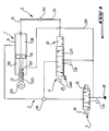
- FIG. 1 there is shown a hydraulic cylinder 1 and its fluid supply circuit 2.
- a piston 10 is slidably mounted inside the body 11 of the cylinder 1, so as to define two chambers therein. variable volume 120 and 130.
- a rod 12 integral with the piston 10 extends in a direction XX 'of sliding of the latter in the body 11.
- the rod 12 passes through the chamber 120 of the jack called “small section”, and protrudes from one end of the latter.
- the chamber 130 of the jack is called "large section”.
- the free end of the rod 12 projecting from the body 11 comprises a member 121 for anchoring the jack 1.
- the body 11 comprises another anchoring member 122, at the end of the jack 1 opposite to organ 121. It is with the aid of these organs 121 and 122 that solicitations from compression and traction along XX 'are applied to cylinder 1.
- circuit 2 contains a suitable hydraulic fluid, such as a conventional liquid. As illustrated, the circuit 2 is connected to the chambers 120 and 130 of the jack 1. This circuit comprises a source of fluid supply under high pressure 2P, as well as an exhaust 2E, such as for example a tarpaulin. It can be seen in FIG. 1 that the small section chamber 120 is permanently connected to the fluid source 2P, by a conduit 220 of the circuit 2.
- a hydraulic control distributor 3 is also shown in FIG. 1.
- This so-called "main” distributor 3 is mounted on the circuit 2, and has two inputs and a single output.
- One of the inputs of the distributor 3 is connected to the exhaust 2E of the circuit 2, and the other to the source of fluid 2P.
- the single outlet is connected, via a hydraulic connection or junction 230 of the circuit 2, to the large section chamber 130 of the jack 1.
- the distributor 3 comprises a sliding drawer with three positions, itself controlled by control means 31 and 32. These means 31 and 32 make it possible to slide the drawer of the distributor 3, and thus to modify its state.
- the 2P fluid source is connected to the chamber 130 in order to increase the volume of the latter, and therefore to cause the extension of the jack 1.
- Another position of this drawer places the distributor 3 in a state according to which the chamber 130 is connected to the exhaust 2E of the circuit. Then, the piston 10 can move in the body 11 so as to reduce the length of the jack 1. It can be said that the jack 1 is controlled by the main distributor 3.
- control of the jack 1 consists in varying the pressure in the chamber 130 so that the distance between the anchoring members 121 and 122 is substantially equal to a value permanently determined by a control circuit (not shown) appropriate and according to which the control means 31 and 32 are actuated.
- a control circuit is most often electrical or electronic, and can be equipped for example with sensors, computers or even direct controls, actuable by an operator.
- a safety device acting as an auxiliary control for controlling the jack 1.
- This device comprises a second distributor 4 with a drawer 40 connected to the rod 12 of the jack by a mechanical connection 5.
- connection 5 when the piston 10 is moved under the effect of a stress and moves away from a predetermined intermediate position, this distance causes, through the rod 12 and the connection 5, a displacement of the slide 40 in a position corresponding to a state of the second distributor 4 such that the piston 10 is then moved in the opposite direction or returned again to its intermediate position.
- the second distributor 4 which is mechanically controlled, varies the pressure in the chamber 130 of the actuator so that it resumes, after being requested, an intermediate length acceptable from the point of view of its use, and at little almost constant.
- the main distributor 3 and the second distributor 4 are both mounted on the same hydraulic circuit 2. More precisely, the distributors 3 and 4 are mounted in parallel. In fact, the distributor 4 also has a single outlet connected to the connector 230, and therefore to the chamber 130, as well as two inputs respectively connected to the source 2P and to the exhaust 2E of the circuit 2. However, one can also imagine that the main distributor and the auxiliary distributor are each connected to a separate supply circuit.
- bypass means capable of cutting off the supply of fluid under high pressure to the jack 1 by the distributor 3 in the event of failure or malfunction.
- control means 31, 32 may be advantageous in certain cases to provide in the safety device bypass means capable of cutting off the supply of fluid under high pressure to the jack 1 by the distributor 3 in the event of failure or malfunction.
- the distributor 3 of FIG. 1 is arranged so that in one of its three positions, the source 2P and the exhaust 2E, as well as the conduit of the circuit 2 connecting the outlet of the distributor 3 and the connector 230, are hydraulically isolated.
- This so-called "closed" state of the distributor 3 corresponds to the central position of its drawer.
- the bypass means have the effect of placing the distributor 3 in the closed state as soon as these control means 31 and 32 undergo a failure.
- the distributor 3 will then be of the so-called "normally closed” type. For example, such an effect can be obtained by connecting the distributor drawer 3 to two opposite balancing springs.
- the means 31 and 32 are constituted by electromagnets.
- these electromagnets 31 and 32 will be controlled so as to prevent them from being excited simultaneously.
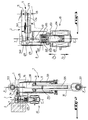
- the distributor 4 which is of the type with four positions, two of which corresponding to a closed state, comprises a housing 411 fixed to the body 11 of the jack 1.
- the drawer 40 which is formed of a series of cylindrical "blocks", is slidably mounted in this housing with its longitudinal axis YY 'of displacement substantially parallel to X-X'.
- the blocks of the drawer 40 are arranged so as to be able to close or clear at least one conduit opening into the bore of the housing 411 where the drawer 40 slide, and connecting the distributor 4 to the circuit 2.
- three conduits are formed in the housing 411 and respectively connect the bore of the drawer 40 to the source 2P, to the exhaust 2E and to the hydraulic connection 230 .
- the mechanical connection 5 is notably constituted by a pivoting lever 54 mounted inside a recess 415 defined jointly by the housing 411 and by the body of the jack 1. It will also be noted here that according to the example illustrated in Figures 2 to 7, the recess 415 constitutes a part of the hydraulic circuit 2 connected to the large section chamber 130 of this jack.
- lever 54 is articulated on a pivot axis 541, integral with the body 11 and roughly perpendicular to a plane defined by the axes X-X 'and Y-Y'.
- the free end of the slide 40 as well as of a feeler 15 connected to the rod 12, protrude into the recess 415.
- the end of one of the branches of the lever 54 extends to the right of the axis YY 'of the drawer 40, while the end of its other branch comes to the right of the axis X-X', along which the probe 15 extends.
- one of the branches of the pivoting lever 54 can come into contact and cooperate with the drawer 40, and the other with the probe 15. Since the probe 15 is connected to the rod 12 of the jack 1, when the piston 10 slides in a given direction along X-X ', the feeler 15 can tilt the lever 54 so that the slide 40 is moved along Y-Y', in a direction opposite to that of the piston.
- the probe 15 has the shape of a finger slidably mounted along XX 'inside the rod 12.
- This finger passes through the piston 10, as well as the chamber 130 of the jack 1, and comprises at its end opposite the lever 54, a projecting shoulder or end piece 151.
- This shoulder 151 is housed with play in a cylindrical recess of the rod 12 and moves along XX 'when the finger 15 slides. It appears from the figures that the end piece 151 constitutes a stop capable of coming into contact with the piston 10, to prevent the feeler 15 from separating from the rod 12 when the latter moves towards the lever 54.
- a spring 125 is interposed between the bottom of the recess of the rod 12 and the end piece 151, in order to elastically urge the feeler 15 against the pivoting lever 54.
- a spring 125 makes it possible to damping the deflections of the piston 10 and of the rod 12, the amplitude of which is greater than that of the possible pivoting of the lever 54, while maintaining contact between the latter and the probe.
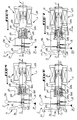
- the lever 54 of the link 5 cooperates with one or more stops, capable of limiting the pivoting thereof according to the corresponding direction of rotation.
- a stop 515 constituted by a hemispherical shoe is screwed into the recess 415 opposite the probe 15 and therefore in line with the axis XX ′.
- the lever 54 can come to bear against the stop 515 when the probe 15 is moved towards the anchoring member 122 over a sufficient length, that is to say when this lever 54 pivots in the trigonometric direction.
- a plug 540 screwed into the recess 415 opposite the drawer 40 can constitute a second stop capable of limiting the pivoting of the lever 54 clockwise in the figures, as for example under the effect of sufficient sliding of the slide 40 along Y-Y ', in a direction indicated by the arrow F1 in FIG. 3.
- the reference numeral 45 generally designates means for deactivating the security device.
- the means 45 are capable of interrupting the mechanical connection 5 between the second distributor 4 and the rod 12, when the main distributor 3 is operating normally. These deactivation or interruption means are therefore actuated alternately exclusively with the derivation means explained above.
- the means 45 are in particular constituted by an electromagnet, the movable core 454 of which is slidably mounted along the axis YY ′ in a fixed body 451 with an excitation coil, as well as by a tip 405 of the drawer 40, by which the latter can be made integral with the core 454.
- the body 451 of the electromagnet is directly fixed by screwing in a threaded housing of the housing 411, opposite the recess 415.
- a part of the drawer 40 at the end of which the end piece 405 is formed protrudes into this recess of the housing 411, as well as inside a threaded bore 453 of the movable core 454.
- This part of the drawer 40 is guided along YY 'in a socket 455, fixed by screwing in the tapped hole 453 of the core. It will be noted here that it is this socket 455 secured to the core 454 which abuts along F2 against the end piece 405 of the drawer 40, in order to separate the latter from the lever 54, when the means 45 are actuated.
- the electromagnet of the deactivation means 45 is provided with means 461 for returning the core 454, capable of request the latter towards the lever 54, that is to say to return it along F1 when the means 45 are at rest.
- return means 461 essentially consist of a helical spring interposed between the body 451 of the electromagnet, and a shoulder of the sleeve 455 projecting from the periphery of the core 454.
- the movable core 454 is provided with means 462 for returning the drawer 40 to a position where it is in contact with the corresponding branch of this lever.
- return means 462 here consist of a helical spring interposed between the sleeve 455 and a part integral with the drawer 40, in order to elastically urge the latter towards the lever 54, and more precisely in the direction of the arrow F1 in FIG. 3 .
- the drawer 40 of the second distributor 4 which is substantially of cylindrical shape, has two intermediate sections with reduced section or peripheral recesses. These peripheral recesses separate three cylindrical blocking and guiding blocks, the diameter of which corresponds to that of the housing of the housing 411 where the drawer 40 is slidably mounted. To allow the hydraulic fluid to circulate between two conduits of circuit 2 formed in the housing 411, one of these recesses devices of the drawer 40 must come opposite these two conduits, and thus establish their connection.
- the safety device is placed in its deactivated position shown in FIG. 7, as explained above.
- the distributor 3 is placed in the closed position (FIG. 1) by the bypass means, and the control of the jack 1 is then controlled by the second distributor 4, as explained below.
- the lever 54 is in a neutral or holding position, in which it is neither in contact nor with the stop 515 nor with stop 540, if provided.
- the lever 54 extends approximately perpendicularly to the axes XX 'and YY' and cooperates with the drawer 40 of the second distributor 4 so that the conduits of circuit 2 connected to the exhaust 2E and at the source 2P each come opposite one of the peripheral recesses of the drawer.
- These recesses are themselves isolated from each other by a block arranged opposite and closing the conduit formed in the housing 411 which is connected to the connector 230, and therefore to the chamber 130 of the jack 1.
- the drawer 40 is in the holding position, the supply of pressurized fluid to the chamber of large section of the jack 1 is interrupted, so that the piston 10 remains in the intermediate position.
- FIG. 6 represents a position or a state of servo-control by supplying the device according to the invention.
- the large section chamber 130 of the jack is connected by the second distributor. 4 at the source 2P of hydraulic fluid under high pressure.
- the chamber 120 is connected to this same source 2P by the conduit 220, but the area of its cross section (perpendicular to the axis XX ') is less than that of the chamber 130, the effort stress applied to the piston 10 by this pressure is greater in the chamber 130 than in the chamber 120. It is understood that in this state, the piston, and therefore the rod 12, are moved so as to move away from the member anchor 122, which has the effect of increasing the length of the jack 1.
- the second distributor 4 is placed in such a state when the piston 10 is moved away from its intermediate position in a direction tending to reduce the length of the jack 1 Indeed, in this case the feeler 15 is moved by the rod 12 until the lever 54 comes to bear against the stop 515 and the drawer 40 closes the duct connected to the exhaust 2E and connects, by l 'intermediate of one of its peripheral recesses, the chamber 130 and the sou rce 2P. Then, the servo-control by supplying the chamber 130 causes a displacement in the opposite or opposite direction of the piston 10, until it is again in its intermediate position, as illustrated in FIG. 4.
- the vehicle equipped with the safety device according to the invention will remain perfectly stable and drivable, even in the event of a malfunction of the main servo control of a stabilization jack.
Landscapes
- Engineering & Computer Science (AREA)
- Mechanical Engineering (AREA)
- Chemical & Material Sciences (AREA)
- Analytical Chemistry (AREA)
- Physics & Mathematics (AREA)
- Fluid Mechanics (AREA)
- General Engineering & Computer Science (AREA)
- Fluid-Pressure Circuits (AREA)
Applications Claiming Priority (2)
| Application Number | Priority Date | Filing Date | Title |
|---|---|---|---|
| FR9300974A FR2701069A1 (fr) | 1993-01-29 | 1993-01-29 | Dispositif de commande de sécurité pour vérin hydraulique asservi. |
| FR9300974 | 1993-01-29 |
Publications (2)
| Publication Number | Publication Date |
|---|---|
| EP0608650A1 true EP0608650A1 (de) | 1994-08-03 |
| EP0608650B1 EP0608650B1 (de) | 1996-04-03 |
Family
ID=9443530
Family Applications (1)
| Application Number | Title | Priority Date | Filing Date |
|---|---|---|---|
| EP19930403202 Expired - Lifetime EP0608650B1 (de) | 1993-01-29 | 1993-12-28 | Sicherheitssteuereinrichtung für einen hydraulischen Arbeitszylinder |
Country Status (3)
| Country | Link |
|---|---|
| EP (1) | EP0608650B1 (de) |
| DE (1) | DE69302083D1 (de) |
| FR (1) | FR2701069A1 (de) |
Cited By (7)
| Publication number | Priority date | Publication date | Assignee | Title |
|---|---|---|---|---|
| FR2722451A1 (fr) * | 1994-07-12 | 1996-01-19 | Peugeot | Systeme de suspension active pour une roue de vehicule automolbile |
| EP0729875A2 (de) * | 1995-02-28 | 1996-09-04 | Samsung Heavy Industries Co., Ltd | Automatische Hinterrad-Zentrierungsvorrichtung für Fahrzeuge mit Vierradlenkung |
| FR2770768A1 (fr) | 1997-11-12 | 1999-05-14 | Sagem | Brosse de nettoyage de dents amovible pour dispositif de pulverisation |
| FR2786132A1 (fr) * | 1998-11-25 | 2000-05-26 | Renault | Dispositif de liaison d'une barre anti-roulis a un organe mobile du train d'un vehicule automobile |
| FR2812704A1 (fr) * | 2000-08-01 | 2002-02-08 | Zf Lenksysteme Gmbh | Actionneur |
| EP1362721A3 (de) * | 2002-05-16 | 2005-03-30 | Bayerische Motoren Werke Aktiengesellschaft | Regelsystem für ein Kraftfahrzeug mit Wankstabilisierung |
| US8672337B2 (en) | 2008-08-12 | 2014-03-18 | Nederlandse Organisatie Voor Toegepast-Natuurwetenschappelijk Onderzoek Tno | Multi-point hydraulic suspension system for a land vehicle |
Citations (8)
| Publication number | Priority date | Publication date | Assignee | Title |
|---|---|---|---|---|
| GB927745A (en) * | 1961-01-05 | 1963-06-06 | Daimler Benz Ag | Apparatus for tilting a vehicle when travelling around a bend |
| US3272062A (en) * | 1965-10-07 | 1966-09-13 | Ltv Electrosystems Inc | Servo valve synchronizer |
| EP0024284A2 (de) * | 1979-08-21 | 1981-03-04 | Messerschmitt-Bölkow-Blohm Gesellschaft mit beschränkter Haftung | Notsteuereinrichtung |
| US4828283A (en) * | 1985-11-13 | 1989-05-09 | Nissan Motor Co., Ltd. | Four wheel steer vehicle control system responsive to suspension characteristic change |
| EP0354113A1 (de) * | 1988-08-02 | 1990-02-07 | Automobiles Peugeot | Vorrichtung zur Lageregelung eines Kraftfahrzeuges |
| EP0354438A1 (de) * | 1988-08-02 | 1990-02-14 | IVECO FIAT S.p.A. | Luftfederung mit konstanter Lage für Kraftfahrzeuge |
| US4936196A (en) * | 1988-11-25 | 1990-06-26 | Teijin Seiki Company Limited | Device for resetting servo actuator to neutral position |
| FR2670716A1 (fr) * | 1990-12-21 | 1992-06-26 | Renault | Dispositif de securite monte sur un verin hydraulique d'anti-roulis actif. |
-
1993
- 1993-01-29 FR FR9300974A patent/FR2701069A1/fr active Pending
- 1993-12-28 DE DE69302083T patent/DE69302083D1/de not_active Expired - Lifetime
- 1993-12-28 EP EP19930403202 patent/EP0608650B1/de not_active Expired - Lifetime
Patent Citations (8)
| Publication number | Priority date | Publication date | Assignee | Title |
|---|---|---|---|---|
| GB927745A (en) * | 1961-01-05 | 1963-06-06 | Daimler Benz Ag | Apparatus for tilting a vehicle when travelling around a bend |
| US3272062A (en) * | 1965-10-07 | 1966-09-13 | Ltv Electrosystems Inc | Servo valve synchronizer |
| EP0024284A2 (de) * | 1979-08-21 | 1981-03-04 | Messerschmitt-Bölkow-Blohm Gesellschaft mit beschränkter Haftung | Notsteuereinrichtung |
| US4828283A (en) * | 1985-11-13 | 1989-05-09 | Nissan Motor Co., Ltd. | Four wheel steer vehicle control system responsive to suspension characteristic change |
| EP0354113A1 (de) * | 1988-08-02 | 1990-02-07 | Automobiles Peugeot | Vorrichtung zur Lageregelung eines Kraftfahrzeuges |
| EP0354438A1 (de) * | 1988-08-02 | 1990-02-14 | IVECO FIAT S.p.A. | Luftfederung mit konstanter Lage für Kraftfahrzeuge |
| US4936196A (en) * | 1988-11-25 | 1990-06-26 | Teijin Seiki Company Limited | Device for resetting servo actuator to neutral position |
| FR2670716A1 (fr) * | 1990-12-21 | 1992-06-26 | Renault | Dispositif de securite monte sur un verin hydraulique d'anti-roulis actif. |
Cited By (9)
| Publication number | Priority date | Publication date | Assignee | Title |
|---|---|---|---|---|
| FR2722451A1 (fr) * | 1994-07-12 | 1996-01-19 | Peugeot | Systeme de suspension active pour une roue de vehicule automolbile |
| EP0729875A2 (de) * | 1995-02-28 | 1996-09-04 | Samsung Heavy Industries Co., Ltd | Automatische Hinterrad-Zentrierungsvorrichtung für Fahrzeuge mit Vierradlenkung |
| EP0729875A3 (de) * | 1995-02-28 | 1998-04-01 | Samsung Heavy Industries Co., Ltd | Automatische Hinterrad-Zentrierungsvorrichtung für Fahrzeuge mit Vierradlenkung |
| FR2770768A1 (fr) | 1997-11-12 | 1999-05-14 | Sagem | Brosse de nettoyage de dents amovible pour dispositif de pulverisation |
| WO1999023975A1 (fr) | 1997-11-12 | 1999-05-20 | Sagem S.A. | Brosse de nettoyage de dents amovible pour dispositif de pulverisation |
| FR2786132A1 (fr) * | 1998-11-25 | 2000-05-26 | Renault | Dispositif de liaison d'une barre anti-roulis a un organe mobile du train d'un vehicule automobile |
| FR2812704A1 (fr) * | 2000-08-01 | 2002-02-08 | Zf Lenksysteme Gmbh | Actionneur |
| EP1362721A3 (de) * | 2002-05-16 | 2005-03-30 | Bayerische Motoren Werke Aktiengesellschaft | Regelsystem für ein Kraftfahrzeug mit Wankstabilisierung |
| US8672337B2 (en) | 2008-08-12 | 2014-03-18 | Nederlandse Organisatie Voor Toegepast-Natuurwetenschappelijk Onderzoek Tno | Multi-point hydraulic suspension system for a land vehicle |
Also Published As
| Publication number | Publication date |
|---|---|
| EP0608650B1 (de) | 1996-04-03 |
| DE69302083D1 (de) | 1996-05-09 |
| FR2701069A1 (fr) | 1994-08-05 |
Similar Documents
| Publication | Publication Date | Title |
|---|---|---|
| WO1999020870A1 (fr) | Carottier | |
| FR2547257A1 (fr) | Systeme de freinage hydraulique pour vehicule automobile | |
| EP1682787B1 (de) | Hydraulisches kupplungsbetätigungssystem mit zwischen dem hauptzylinder und dem nehmerzylinder des systems angeordneten servomitteln | |
| EP0608650B1 (de) | Sicherheitssteuereinrichtung für einen hydraulischen Arbeitszylinder | |
| FR2695616A1 (fr) | Frein de bicyclette à leviers articulés. | |
| EP0428439B1 (de) | Antirollvorrichtung für ein Kraftfahrzeug | |
| FR2935128A1 (fr) | Procede d'autopilotage de transmission et dispositif de transmission autopilotable pour vehicules remorques, en particulier pour machines a vendanger tractees, attelables a un vehicule auto propulseur | |
| FR2468775A1 (fr) | Distributeur hydraulique | |
| FR2522109A1 (fr) | Soupape a regeneration | |
| EP0835482B1 (de) | Druckregelndes elektromagnetventil für hydraulischen kreis | |
| FR2471524A1 (fr) | Dispositif hydrodynamique pour transmettre un couple mecanique, et notamment frein hydrodynamique | |
| EP1592600B1 (de) | Verfahren zur steuerung der richtung eines kraftfahrzeugs | |
| EP0037348A2 (de) | Sicherheitseinrichtung für eine hydraulisch arbeitende Hebevorrichtung | |
| WO1996011828A1 (fr) | Electrovalve de regulation de pression hydraulique et application aux circuits de freinage | |
| EP0028544A1 (de) | In verschiedenen Stellungen blockierbares Scharnier | |
| EP0939715B1 (de) | Hilfskraftunterstütztes bremssystem mit verbesserter hydraulischer reaktion | |
| EP0801232A1 (de) | Hydraulisches Steuerventil für Servosteuerung eines Luftfahrzeugs, insbesondere Hubschraubers | |
| FR2757223A1 (fr) | Installation hydraulique a au moins un circuit d'utilisation du type a centre ferme | |
| EP1599375B1 (de) | Verfahren zur richtungssteuerung eines kraftfahrzeugs | |
| EP0033690A1 (de) | Vorrichtung zur Anpassung der Bremskraft bei Zweikreis-Bremsanlagen | |
| FR2697473A1 (fr) | Dispositif de suspension, notamment pour une roue arrière d'un véhicule automobile et amortisseur utilisé dans un tel dispositif. | |
| EP0054469A1 (de) | Trommelbremse mit Bremskraftregelung | |
| FR2746154A1 (fr) | Frein a commande hydropneumatique | |
| FR2508566A1 (fr) | Distributeur de commande de verin | |
| FR2577188A1 (fr) | Direction assistee hydraulique de vehicule automobile |
Legal Events
| Date | Code | Title | Description |
|---|---|---|---|
| PUAI | Public reference made under article 153(3) epc to a published international application that has entered the european phase |
Free format text: ORIGINAL CODE: 0009012 |
|
| AK | Designated contracting states |
Kind code of ref document: A1 Designated state(s): DE GB IT |
|
| 17P | Request for examination filed |
Effective date: 19950130 |
|
| 17Q | First examination report despatched |
Effective date: 19950222 |
|
| GRAH | Despatch of communication of intention to grant a patent |
Free format text: ORIGINAL CODE: EPIDOS IGRA |
|
| GRAA | (expected) grant |
Free format text: ORIGINAL CODE: 0009210 |
|
| AK | Designated contracting states |
Kind code of ref document: B1 Designated state(s): DE GB IT |
|
| PG25 | Lapsed in a contracting state [announced via postgrant information from national office to epo] |
Ref country code: IT Free format text: LAPSE BECAUSE OF FAILURE TO SUBMIT A TRANSLATION OF THE DESCRIPTION OR TO PAY THE FEE WITHIN THE PRESCRIBED TIME-LIMIT;WARNING: LAPSES OF ITALIAN PATENTS WITH EFFECTIVE DATE BEFORE 2007 MAY HAVE OCCURRED AT ANY TIME BEFORE 2007. THE CORRECT EFFECTIVE DATE MAY BE DIFFERENT FROM THE ONE RECORDED. Effective date: 19960403 Ref country code: GB Effective date: 19960403 |
|
| REF | Corresponds to: |
Ref document number: 69302083 Country of ref document: DE Date of ref document: 19960509 |
|
| PG25 | Lapsed in a contracting state [announced via postgrant information from national office to epo] |
Ref country code: DE Effective date: 19960704 |
|
| GBV | Gb: ep patent (uk) treated as always having been void in accordance with gb section 77(7)/1977 [no translation filed] |
Effective date: 19960403 |
|
| PLBE | No opposition filed within time limit |
Free format text: ORIGINAL CODE: 0009261 |
|
| STAA | Information on the status of an ep patent application or granted ep patent |
Free format text: STATUS: NO OPPOSITION FILED WITHIN TIME LIMIT |
|
| 26N | No opposition filed |