EP0607433B1 - Quartz glass plate large in size and high in purity, and method and device for making said plate - Google Patents
Quartz glass plate large in size and high in purity, and method and device for making said plate Download PDFInfo
- Publication number
- EP0607433B1 EP0607433B1 EP92916522A EP92916522A EP0607433B1 EP 0607433 B1 EP0607433 B1 EP 0607433B1 EP 92916522 A EP92916522 A EP 92916522A EP 92916522 A EP92916522 A EP 92916522A EP 0607433 B1 EP0607433 B1 EP 0607433B1
- Authority
- EP
- European Patent Office
- Prior art keywords
- quartz glass
- tube
- glass tube
- plate
- opening
- Prior art date
- Legal status (The legal status is an assumption and is not a legal conclusion. Google has not performed a legal analysis and makes no representation as to the accuracy of the status listed.)
- Expired - Lifetime
Links
Images


Classifications
-
- C—CHEMISTRY; METALLURGY
- C03—GLASS; MINERAL OR SLAG WOOL
- C03B—MANUFACTURE, SHAPING, OR SUPPLEMENTARY PROCESSES
- C03B20/00—Processes specially adapted for the production of quartz or fused silica articles, not otherwise provided for
-
- C—CHEMISTRY; METALLURGY
- C03—GLASS; MINERAL OR SLAG WOOL
- C03B—MANUFACTURE, SHAPING, OR SUPPLEMENTARY PROCESSES
- C03B23/00—Re-forming shaped glass
- C03B23/04—Re-forming tubes or rods
- C03B23/047—Re-forming tubes or rods by drawing
-
- C—CHEMISTRY; METALLURGY
- C03—GLASS; MINERAL OR SLAG WOOL
- C03B—MANUFACTURE, SHAPING, OR SUPPLEMENTARY PROCESSES
- C03B23/00—Re-forming shaped glass
- C03B23/02—Re-forming glass sheets
- C03B23/037—Re-forming glass sheets by drawing
-
- C—CHEMISTRY; METALLURGY
- C03—GLASS; MINERAL OR SLAG WOOL
- C03B—MANUFACTURE, SHAPING, OR SUPPLEMENTARY PROCESSES
- C03B23/00—Re-forming shaped glass
- C03B23/04—Re-forming tubes or rods
- C03B23/06—Re-forming tubes or rods by bending
-
- Y—GENERAL TAGGING OF NEW TECHNOLOGICAL DEVELOPMENTS; GENERAL TAGGING OF CROSS-SECTIONAL TECHNOLOGIES SPANNING OVER SEVERAL SECTIONS OF THE IPC; TECHNICAL SUBJECTS COVERED BY FORMER USPC CROSS-REFERENCE ART COLLECTIONS [XRACs] AND DIGESTS
- Y10—TECHNICAL SUBJECTS COVERED BY FORMER USPC
- Y10S—TECHNICAL SUBJECTS COVERED BY FORMER USPC CROSS-REFERENCE ART COLLECTIONS [XRACs] AND DIGESTS
- Y10S65/00—Glass manufacturing
- Y10S65/08—Quartz
-
- Y—GENERAL TAGGING OF NEW TECHNOLOGICAL DEVELOPMENTS; GENERAL TAGGING OF CROSS-SECTIONAL TECHNOLOGIES SPANNING OVER SEVERAL SECTIONS OF THE IPC; TECHNICAL SUBJECTS COVERED BY FORMER USPC CROSS-REFERENCE ART COLLECTIONS [XRACs] AND DIGESTS
- Y10—TECHNICAL SUBJECTS COVERED BY FORMER USPC
- Y10S—TECHNICAL SUBJECTS COVERED BY FORMER USPC CROSS-REFERENCE ART COLLECTIONS [XRACs] AND DIGESTS
- Y10S65/00—Glass manufacturing
- Y10S65/09—Tube
Definitions
- the present invention relates to large quartz glass plate and the manufacturing method and equipment to produce it.
- the present invention relates to large quartz glass plate of high transparency and purity, in the form of flat plate and the manufacturing method and equipment to produce it.
- the quartz glass used for these applications retains high viscosity even at high temperatures, which makes it difficult to form and cast it when it is melted and, therefore, difficult to form it into plate.
- quartz glass plate is produced.
- One is by cutting a block of quartz glass into thin sheets.
- the other is a process in which a quartz glass tube is opened to form a quartz glass plate.
- the prior art applied in the former method employs a technology in which plate is formed from pulverized powder by refining natural crystal or quartzite and then heating the powder electrically or with a gas burner to melt and fuse it into a block of quartz glass, which is then cut into plate using a diamond cutter or the like.
- the surface of the plate thus obtained is rough, necessitating a surface smoothing treatment, such as a special separate polishing operation to make the surface transparent.
- Quartz glass is a material with superior transparency and light transmission, and particularly in applications such as observation ports, lamp covers and the like, the material is usually required to have excellent optical transparency. Therefore, it is necessary to perform transparency finishing with some type of surface treatment, for example, surface fusing with fire or specular glossing with a granular abrasive after the coarse polishing on the plate material, which leaves a rough surface and reduced transparency as described in the previous paragraph.
- This transparency finishing treatment is extremely labor intensive and time consuming.
- the material can be easily contaminated by impurities and metal elements which will have detrimental effects on semiconductors. In the surface fusing treatment using fire, thermal distortion tends to cause cracking, so this method is highly disadvantageous from an industrial point of view.
- the aforementioned block forms are manufactured by melting and fusing a pulverized powder of natural crystal or quartzite in a special die, impurities or reactive gasses originating in the die body, as well as residual gasses within the melted substance tend to be retained in the form of bubbles in the melted, high viscosity quartz glass. Since this tendency becomes more pronounced as the size of the block body increases, inevitably there are foreign substances and bubbles in large plate cut from such blocks. This makes it difficult to use such plate for products that require a high degree of transparency such as quartz glass observation ports and lamp covers.
- a quartz glass tube 100 is slit open in the direction of the axis or the quartz glass tube is cut into two and a quartz glass dowel is welded, centered onto its edge, to form an operating handle 101. While holding the handle 101, the opened quartz glass tube 100 is heated and softened all over.
- the whole quartz glass tube is opened into a curved plate, then while heating and softening part of it, the softened section 100a is pressed and flattened on a carbon plate 103 with a carbon press 104 or the like. After that, the operation is repeated while the welded position of the handle 101 is relocated to flatten other areas sequentially in stages to create the quartz glass plate.
- Another method of the prior art is that in which the quartz glass tube 100, already opened in the form of a curved plate as described above, is then sandwiched between carbon slabs while being heated and softened to make it into a flat plate.
- the objective of the present invention is to address these problems of the prior art: to provide a large quartz glass plate with no bubbles and to provide a manufacturing method and manufacturing equipment to produce such a plate.
- This object is solved by the method of claim 1, the manufacturing device of claim 13 and the quartz glass plate of claim 23.
- Claim 12 is directed to a method for manufacturing a curved quartz glass plate.
- the subclaims relate to preferred embodiments of the invention.
- Embodiments of the invention provide quartz glass plates with no surface waviness or surface roughness and with a high degree of flatness and provide manufacturing methods and manufacturing equipment to produce them.
- the means of pulling 2 that has the leading edge 1b of the glass tube 1 fixed onto it is made to pull linearly in an approximately tangential direction from the opening leading edge 1b to make the glass tube 1 into a flat plate.
- the initial heating position for the heating bodies 3A and 3B is not necessarily set at the leading edge 1b of the opening.
- the means of pulling 2 grips the leading edge 1b of the opening, it may not be possible to directly heat the leading edge 1b of the opening. In this case, heating may be started at a position slightly further in than the leading edge 1b of the opening, out of the way of the gripped area.
- the peripheral speed of the quartz glass tube 1 and the pulling speed of the means of pulling 2 are not necessarily the same. By setting these speeds appropriately, it is possible to adjust the thickness of the formed flat plate thicker or thinner in relation to the thickness of the glass tube 1. For example, by setting the pulling speed higher than the peripheral speed of the quartz glass tube 1, large, flat glass plate thinner than the tube material can be produced. Conversely, by setting the pulling speed slower than the peripheral speed of the quartz glass tube 1, large, flat glass plate thicker than the tube material can be produced.
- This structure can be embodied by making the means of pulling 2 directly grip the leading edge 1b of the opening in the quartz glass tube 1. It would be difficult to form a high-purity quartz glass plate if the grip was made of a metal, since impurities would enter from the grip due to the heat during the heating and softening process. Therefore, it is desirable to grip with a high-purity, highly heat resistant carbon or ceramic material such as alumina, SiC, zirconia, silicon nitride or the like. However, it is still quite difficult to completely eliminate contamination of impurities spreading from the grip area.
- the heating of the aforementioned glass tube 1 may be performed from one side. However, if there is a difference in temperature between the front and rear sides, consistent and even pulling becomes difficult.
- heating should be done from both the front and rear of the quartz glass tube 1 over the entire width in the direction of the tube shaft.
- the aforementioned heating bodies 3A and 3B may take the form of bar heating bodies made of SiC, carbon or the like. Or, another possible structure is a body of integrated burners in which a great number of burner nozzles are arranged in a row.
- it is advisable to move them in a reciprocating motion in the heating area relative to the quartz glass tube 1 in the direction of the tube shaft in order to eliminate inconsistency of heat supply in the direction of the shaft of the quartz glass tube1. It will be even more preferable to soften the glass tube 1 over the entire width in a band-like area while moving the heating bodies 3A and 3B in a reciprocating motion.
- the heat source may be placed inside the quartz glass tube 1 which is the base material in the present invention, it is not feasible to use a tube with an extremely small diameter. In practice, it is desirable to use a transparent quartz glass tube with a diameter ranging from 100 to 500mm and a thickness of 2 to 20mm.
- the quartz glass plate should have a high degree of transparency and purity.
- the total content of the following elements: Na, Li, Fe, Al, Cu, Ca, Ni, B, Mg, Y, Ti and Cr, should be 100 ppm (weight) or less. Even more preferably, the content of elements such as Na, K and Cu and especially Ca, which contaminates particularly easily, should be 0.5 ppm or less.
- the present invention relates to a method in which flat plate material is formed from a quartz glass tube 1, and also relates to the reverse process, in which a large quartz glass plate is provided and then heated and softened linearly from one end to the other sequentially over the entire width, and is simultaneously pulled in such a way that it becomes curved from one end to a specific shape in order to form a curved glass plate.
- the second aspect of the present invention provides optimum equipment for implementing the manufacturing method comprising a quartz glass tube 1 which has an opening 1a over a specific width in the direction of the tube shaft, preferably in the form of a band, means 5 to rotate the aforementioned glass tube 1 with its tube shaft as the center of the rotation and means 2 for pulling the glass tube 1 in a line approximately tangential to the leading edge 1b of the opening in the glass tube 1 while the glass tube 1 is heated and softened in a band-like area over the entire width of the tube, in the direction of the tube shaft.
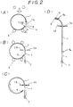
- means 6 for supporting the quartz glass tube 1 by the circumferential surface is provided and the present invention is embodied by a structure A in which the axis of the means 5 of rotation and the axis of the quartz glass tube 1 are made to align and coincide.
- structure B the means 6 of support and means 5 of rotation are structured so that they can move freely in the plane of cross section of the glass tube.
- the trailing edge 1c of the opening that faces the leading edge 1b of the opening, be positioned at a location that does not intersect the line tangential to the leading edge 1b. Therefore, it is desirable to structure the apparatus in such a way that it is possible to set the initial support position of the means of support for the quartz glass tube 1 at a location that makes the leading edge 1b of the opening further out, horizontally, from a vertical line through the tube axis, than the trailing edge 1c of the opening.
- the means 5 of rotation is structured so that it directly grips the leading edge 1b of the opening in the quartz glass tube 1 by using a clamping member or the like, because impurities are likely to be transferred from the clamping member at the time of heating and softening.
- the structure of the means 5 of rotation should be a rotating plate or arm member that can rotate around the rotating shaft as the center of rotation without the clamping member directly gripping the leading edge 1b of the opening. It is preferable to structure it in this way; some quartz glass material 8 or the like is fused to the trailing edge 1c of the opening of the glass tube 1, that is clamped by the arm member, thus making it possible to rotate the quartz glass tube 1 in conformance with the rotation of the arm part.
- the gripping member that grips the trailing edge 1c of the said opening via a carbon or ceramic material with high heat resistance, including alumina SiC, zirconia, silicon nitride and the like, first clamps and secures the trailing edge 1c of the opening of the glass tube 1 and then the quartz glass tube 1 rotates in conformance with the rotation of the arm member.
- a carbon or ceramic material with high heat resistance including alumina SiC, zirconia, silicon nitride and the like.
- the means of heating be structured with the heating bodies 3A and 3B, being a pair of bar heaters that are placed facing each other across the glass tube 1, or heating bodies 3A and 3B can take the form of burners or the like, in which case, the pair of heating bodies 3A and 3B are moved back and forth in the direction of the tube shaft to evenly soften a band-shaped area over the entire width of the glass tube 1.
- the quartz glass tube 1 that can be processed with the aforementioned equipment have a diameter of at least 100mm because it is manufactured by pulling the glass tube 1 from the leading edge 1b of the opening in the direction of a tangential line. Also, if it is too thin, it will be deformed at the time of heating and softening and if it is too thick, heating cannot be done evenly. Therefore, the ideal thickness is 2 ⁇ 20mm.
- a flat plate which is manufactured thus from such a quartz glass tube 1 will be a flat, high-purity, high transparency quartz glass plate with its long side at least 300mm with a thickness of 2 ⁇ 20mm.
- quartz glass tube 1 is formed from a relatively small quartz glass ingot, it has almost no bubbles or impurities present, as is likely in a large block. Therefore, a quartz glass plate formed from this ingot will have a high degree of purity and transparency, ideal for observation ports and square tanks.
- a transparent quartz glass plate in which the total content of the following elements; Na, Li, Fe, Al, Cu, Ca, Ni, B, Mg, Y, Ti, and Cr is 100 ppm (weight) or less. Furthermore, the content of elements such as Na, K and Cu and especially Ca, which contaminates particularly easily, can be held down to 0.5 ppm or less.
- the resulting transparent quartz glass plate will be ideal for observation ports, single-crystal, pull-up devices and square wash tanks for wafers.
- Figure 1 is a basic structural diagram of the manufacturing system of the present invention.
- Figure 2 is a series of operation diagrams showing the manufacturing process.
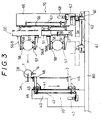
- Figure 3 is a front view of the overall structure of the equipment.
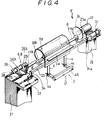
- Figure 4 is a perspective view of the structure of key parts.
- Figure 5 shows the prior art process in which a quartz glass tube is flattened into a plate.
- Figure 3 shows a overall structural view of the flat plate manufacturing system in an embodiment of the present invention, which includes a support mechanism 50 that supports a quartz glass tube 1 which has a band-like opening running in the direction of the tube shaft which is supported with two pairs of support rollers 57, 58, one each at the top and bottom, a support delivery device 70 consisting of a delivery mechanism 60 that transports the support mechanism 50 to a specific position in front of the flat plate forming device 10, means 5 of rotation that rotates the quartz glass tube 1 around the tube shaft center, means 3 of heating to heat and soften the glass tube 1 in a band-shaped area over-the entire width in the direction of the tube shaft.
- the flat plate forming device 10 consisting of a means 2 of pulling that pulls the heated and softened glass tube 1 in a line approximately tangential to the leading edge 1b of the opening.
- the delivery mechanism 60 consists of a screw shaft 61 that is provided on the base body 80 and runs horizontally, extending towards the flat plate forming device 10, a horizontal table 64 that advances toward, and withdraws from the flat plate forming device 10 by means of forward and reverse rotation of the drive motor 63 via the nut section 62 that is threaded on to the said screw shaft 61 and the vertical tower 65 that is erected vertically on the horizontal table 64.
- a vertical guide rail 66 is provided and inside the tower 65, a vertical screw shaft 67 is provided that extends vertically, parallel with the guide rail 66.
- a drive motor 68 that rotates the said vertical screw shaft 67 in both forward and reverse directions is also provided in the tower.
- the vertical stay section 51 is securely mounted in a bracket frame 52, which is fitted to the guide rail 66 so that the bracket frame can be freely elevated and lowered, being linked to the vertical screw shaft 67 via the nut section 52a.
- the support mechanism 50 is elevated and lowered via the bracket frame 52 along the guide rail 66 by rotating the vertical screw shaft 67 in the forward and reverse directions, driven by the drive motor 68.
- the support mechanism 50 consisting of the drive motor 53 and the vertical stay 51, in which a rotating screw shaft 54 rotates in the forward and reverse directions, driven by the drive motor 53, is vertically mounted, extending almost the entire length of the stay.
- a pair of support stays 56A and 56B are elevated and lowered, traveling toward and away from each other through the reverse and forward rotation of the rotating screw shaft 54 on to which the nut section 55 is threaded.
- the support stays 56A and 56B extend horizontally from the vertical stay 51 where the aforementioned nut section 55 is mounted, to support the pairs of support rollers 57 and 58 at their shafts which are located one pair each on the upper and lower surfaces that face each other. Between the support rollers 57 and 58, it is possible to clamp and secure the quartz glass tube 1.
- the quartz glass tube 1 After mounting the quartz glass tube 1 on the pair of support rollers 57 on support stay 56A , the quartz glass tube 1 can be clamped as the two support stays 56A and 56B approach each other by rotating the screw shaft 54 in the forward direction through the drive motor 53.
- the means 5 of rotation includes support bases 21 and 22, located on either side in the direction of the shaft and a space between them for placing the quartz glass tube 1.
- a drive motor 23 is provided with an attached rotating plate 24.
- a driven rotating mechanism 6B is provided, aligned with the extended line of the shaft of the drive motor 23.
- the circular rotating plate 24 is mounted facing opposite the quartz glass tube 1 on the rotating shaft 23a of the drive motor 23.
- a clamping member 11A is provided to clamp the band-like glass plate 8, one edge of which is fused to the trailing edge 1c of the opening in the quartz glass tube 1.
- the distance between the center of the rotating plate 24 and the clamping position of the clamping member 11A (radius) must match the radius of the quartz glass tube 1.
- the driven rotating mechanism 6B includes a pair of shaft bearings 26A and 26B that are mounted on a sliding table 26 which can move along the two parallel rails 25 which extend across the base 21 in the direction of the shaft.
- the distance between the center of the aforementioned large diameter shaft 28 and the clamping position of the clamping member 11B (radius) must be the same as the radius of the quartz glass tube 1.
- a hydraulic cylinder 31 is mounted parallel with the axis that connects the drive motor 23 and the large diameter shaft 28.
- a guide rail 32 is provided along the same axis.
- These two rails are bridged by a support body 33, which is provided with a pair of heating bodies 3A and 3B mounted on to it.
- One end of the support body 33 is secured on to the shaft section of the hydraulic cylinder 31 and the other end is secured on to the perpendicular bracket 34 which is fitted onto the guide rail 32 in such a way that back and forth movement of the structure is possible along the axis by advancing and retracting the hydraulic cylinder 31.
- a sub support body 33B that is bent to form an L shape is provided at the half way position through the range of movement along the axis so that it is opposite support body 33, facing it across the leading edge 1b of the opening in the quartz glass tube 1.
- Heating members 3A and 3B which are more or less flat bars in shape, and are each integrated body consisting of a great number of burner nozzles, are provided on the two support bodies 33 and 33B.
- the length of the stroke of the hydraulic cylinder 31 and the guide rail 32 must be set at a length which makes it possible to keep the sub support body 33B from coming into contact with the quartz glass tube 1.
- the heating bodies 3A and 3B are structured by providing a great number of burner nozzles in rows so that the jets are aimed toward the quartz glass tube 1. They are structured in such a way that jets of flame from propane or oxyhydrogen fuel can be provided along their length, which should be slightly greater than the length of the shaft of the quartz glass tube.
- the means of pulling 2 includes a vertical guide rail 41 mounted on the front side of the vertical table 40 that is erected vertically on the base 80, a vertical screw shaft 42 that extends vertically and parallel with the guide rail 41 inside the vertical table 40, and a drive motor 43 that rotates the vertical screw shaft 42 in the forward and reverse directions.
- the pulling table 45 connected with the vertical screw shaft 42 via the nut section 46 is fitted on the guide rail 41 so that it can be elevated and lowered freely.
- clamping members 44 are provided to clamp the band-like glass plate 4.
- the pulling table 45 has arm sections on both sides extending toward the quartz glass tube 1 with the clamping members 44 for the band-like glass plate 4, one end of which are bonded to the leading edge of the opening 1b in the quartz glass tube 1 and the other end of which extends vertically down to the clamping members 44 attached to the end of the arm sections.
- the drive motor 23 must have an internal speed changer so that its rotating speed can be freely adjusted.
- a high-purity, high transparency quartz glass tube 1 with an external diameter of 240mm and a thickness of 4mm is cut to a length of 500mm . Then a band-like opening is created in the tube to a width of ⁇ : approximately 10 ⁇ 15° (approximately 30mm) to create an opened quartz glass tube 1.
- the impurity contents of the glass tube 1 is 200ppb or less in total content of Na, Li, Fe, Al, Cu, Ca, Ni, B, Mg, Y, Ti and Cr.
- the aforementioned distance h can be any distance as long as there is no hindrance to the band-like glass plate 4, a more detailed explanation of which will be given later, which is fused to the leading edge 1b of the opening for pulling the glass tube 1.
- the opening angle ⁇ can be set arbitrarily within the range of 10 ⁇ 15° according to the distance required.
- the quartz glass tube 1 After the quartz glass tube 1 is set in the specific position, it is positioned with the lower and upper support stays 56A and 56B which approach each other by rotating the drive motor 53 within the vertical stay 51 and then the quartz glass tube 1 is held within the upper and lower pairs of support rollers 57 and 58.
- the support mechanism 50 that is now holding the quartz glass tube 1 first elevates the quartz glass tube 1 via the drive motor in the vertical tower 65, to a height that matches the axis of the means 5 of rotation on the flat plate forming device 10. Then it moves the glass tube 1 horizontally to a position that is aligned with the axis of the means 5 of rotation on the flat plate forming device 10 by sliding the horizontal table 64.
- the piston shaft 31a of the hydraulic cylinder 31 must be extended so that the glass tube 1 will not contact the sub-support body 33B of the heating mechanism 3A.3B at this time.
- band-like quartz glass plates 8 made of high-purity synthetic quartz glass are fused horizontally in the direction of the shaft on to each end of the tube aligned with the trailing edge 1c of the opening. Then, each of them is clamped by clamping member 11a of the rotating plate 24, or the clamping member at the end of the rotating arm 29.
- band-like quartz glass plates 4 are fused on to the end surface of the leading edge 1b of the opening at both the right and left sides in such a way that they will extend vertically downwards along a line tangential to the quartz glass tube 1 and their lower ends are clamped by the clamping members 44 of the pulling table 45.
- the drive motor 53 inside the vertical stay 51 is rotated in the reverse direction to increase the distance between the lower and upper support stays 56A and 56B which have been positioning and supporting the quartz glass tube 1. Then, the delivery mechanism 60 is retracted from the supporting position and returned to its original position.
- the hydraulic cylinder 31 is retracted so that the sub-support body 33 of the heating mechanism 30 can enter the quartz glass tube 1.
- the hydraulic cylinder 31 should be structured so that heating bodies 3A and 3B can face each other across the leading edge 1b of the opening at this time.
- the pulling speed is made to perfectly match the rotation speed throughout the entire period, then the thickness of the resulting flat plate will be exactly the same as that of the quartz glass tube. If the pulling speed is set slightly higher, a flat plate that is slightly thinner will result. Conversely, by making the pulling speed slower, a flat plate that is slightly thicker than the quartz glass tube 1 will result.
- plate forming is performed to the position indicated in Figure 2(D).
- the three operations; heating by the heating bodies 3A and 3B, rotation by means 5 of rotation and pulling by means 2 of pulling, are all stopped simultaneously.
- the section at the trailing edge 1c of the opening which has not been flattened is cut off to form a completed flat plate .
- specified finishing treatments such as washing, annealing or the like have been performed, the plate is ready to be shipped as a product.
- the quartz glass plate thus stretched into a flat plate in this manner is then cooled and formed into a large, high transparency quartz glass plate.
- the plate prepared in this manner does not have any waviness on the surface and the impurity content is 200ppb or less in Na, Li, Fe, Al, Cu, Ca, Ni, B, Mg, Y, Ti and Cr, showing hardly any change from the impurity content before processing.
- a similar transparent quartz glass tube 1 with an external diameter of 240mm, a thickness of 4mm, a length of 500mm and an opening width of approximately 30mm was used to produce a quartz glass plate by following a procedure similar to that described above with a rotating speed of 60mm/min. In this case, the pulling speed was changed to: 50mm/minute, 60mm/minute, 65mm/ minute and 70mm/minute.
- the resulting plate had differing thicknesses of 4.8mm, 4.0mm, 3.7mm and 3.4mm respectively.
- the flat plate formed in this way did not have any surface waviness and were otherwise good quality plate.
Landscapes
- Chemical & Material Sciences (AREA)
- Engineering & Computer Science (AREA)
- Materials Engineering (AREA)
- Organic Chemistry (AREA)
- Glass Melting And Manufacturing (AREA)
- Re-Forming, After-Treatment, Cutting And Transporting Of Glass Products (AREA)
Abstract
Description
On the front of the
Claims (25)
- A method for manufacturing a quartz glass plate, whereina quartz glass tube (1) is provided with an opening (1a) which extends in the direction of the tube axis, andsaid tube is heated and softened in a band-like area which extends over the entire tube length in the direction of the tube axis and said band-like area of heating is moved relative to the tube along its circumference while said tube (1) is pulled in approximately tangential direction from said band-like area, to convert said tube into a flat plate.
- The method of claim 1, wherein:a position of heating said tube (1) is fixed at the initial position of the leading edge (1b) of said opening (1a) in said tube (1), and while said tube (1) is rotated towards said fixed heating position, it is pulled in approximately tangential direction from said leading edge (1b) of said opening (1a), to flatten said tube (1).
- The method of claim 1 or 2, wherein said quartz glass tube (1) is pulled at a pulling speed approximately equal to the peripheral speed of said quartz glass tube (1).
- The method of claim 1 or 2, wherein said quartz glass tube (1) is pulled at a pulling speed which is faster than the peripheral speed of said quartz glass tube (1) to form a large quarts glass plate with reduced thickness.
- The method of claim 1 or 2, wherein said quartz glass tube (1) is pulled at a pulling speed which is slower than the peripheral speed of said quartz glass tube (1) to form a large quartz glass plate with increased thickness.
- The method of claim 2, wherein said quartz glass tube (1) is rotated and pulled in such a manner that it does not come in direct contact with either means (2) of pulling or means (5) of rotating.
- The method of claim 6, wherein said quartz glass tube (1) is pulled while the leading edge (1b) of the opening (1a) of said glass tube (1) is linked to said means (2) of pulling by a quartz glass connecting piece.
- The method of any of claims 1 to 7, wherein said quartz glass tube (1) is heated from both the inner and the outer sides in said band-like area.
- The method of any of claims 1 to 8, wherein said quartz glass tube (1) is evenly softened in said band-like area by heating means (3a, 3b) which are moved in relative reciprocal motion, in the direction of the tube axis.
- The method of any of the preceding claims, wherein said quartz glass tube (1) has a minimum diameter of 100 mm and a thickness of 2 to 20 mm.
- The method of any of the preceding claims, wherein said quartz glass tube (1) is made of transparent synthetic quartz glass.
- A method for manufacturing a curved quartz glass plate, whereina flat quartz glass plate is provided, andsaid plate is heated and softened in a band-like area which extends over its entire width and said band-like area is moved while said plate is pulled in such a direction that said curved glass plate is formed.
- A device for manufacturing a quartz glass plate from a quartz glass tube (1) provided with an opening (1a) which extends in the direction of the tube axis, comprising;heating means (3a, 3b) for heating and softening said tube (1) in a band-like area which extends over the entire tube length in the direction of the tube axis,rotation means (5) for letting said band-like area of heating move relative to said tube (1) along the tube's circumference, andpulling means (2) for pulling said tube (1) in approximately tangential direction from said band-like area, to convert said tube into a flat plate.
- The device of claim 13 whereinsaid heating means (3a, 3b) is fixed at the initial position of the leading edge (1b) of said opening (1a) of said quartz glass tube (1);said rotation means (5) rotates said quartz glass tube (1) towards said fixed heating position; andsaid pulling means (2) pulls said quartz glass tube (1) in approximately tangential direction from said leading edge of said opening.
- The device of claim 13 or 14, wherein:a means of support (6) is provided which supports said quartz glass tube (1) on its peripheral surface and said means of support (6) and said means of rotation (5) are structured so that they can move, relative to each other in the plane of the cross section of said quartz glass tube (1) that intersects the axis of said quartz glass tube (1) at a right angle, and so that a shaft of said means of rotation (5) and said axis of said quartz glass tube (1) are aligned.
- The device of claim 15, wherein:means are provided to set an initial supporting position of said means of support (6) for said quartz glass tube (1) outside of the tube axis in the direction of the tube radius, from the vantage point of said leading edge (1b) of said opening (1a) in relation to said trailing edge (1c) of said opening (1a).
- The device of any of claims 13 to 16, wherein:said means of rotation (5) is structured with a rotating member (24) that rotates centered on said axis of said quartz glass tube (1) so that, once said rotating member is connected to said trailing edge side of said opening of said quartz glass tube (1) via a fused quartz glass member (8), said quartz glass tube (1) rotates in conformance with the rotation of said rotating member (24).
- The device of any of claims 13 to 17, wherein:the peripheral speed of the quartz glass tube (1), rotated by said means of rotation (5), is equal to the pulling speed of said means of pulling (2).
- The device of any of claims 13 to 17, comprising means for changing the peripheral speed of said quartz glass tube (1) rotated by said means of rotation (5) relative to said pulling speed of said means of pulling (2).
- The device of any of claims 13 to 19, wherein:said means of pulling (2) is linked with said leading edge (1b) of said opening (1a) of said quartz glass tube (1) by a quartz glass member (4).
- The device of any of claims 13 to 20, wherein:said heating means (3a, 3b) comprises a pair of burner members (3a, 3b) or a pair of bar heating bodies that are positioned facing each other across said quartz glass tube (1).
- The device of claim 21, wherein:said glass tube (1) is evenly softened in a linear, band-shaped area over its entire width while said pair of heating bodies (3a, 3b) are moved back and forth in the direction of the tube axis.
- A large quartz glass plate which is characterised by the procedure of its manufacture, wherein:a quartz glass tube (1) with an opening (1a) of a specific width in the direction of the tube axis is heated and softened in a band-shaped area which progresses in the direction of the circumference, to form a flat plate, and wherein:the length of said flat plate is at least 300 mm and the thickness is 20 mm or less.
- The large quartz glass plate according to claim 23, which meets the following specifications:the maximum total content of metal elements in said glass plate is 100 ppm for Na, Li, Fe, Al, Cu, Ca, Ni, B, Mg, Y, Ti and Cr and, in particular, each of the following elements, Na, K, Cu and Ca are present at 0.5 ppm or less.
- The large quartz glass plate according to claim 23, which meets the following specifications:the maximum total content of metal elements in said glass plate is 200 ppb for Na, Li, Fe, Al, Cu, Ca, Ni, B, Mg, Y, Ti and Cr.
Applications Claiming Priority (1)
| Application Number | Priority Date | Filing Date | Title |
|---|---|---|---|
| PCT/JP1992/000976 WO1994003404A1 (en) | 1992-07-31 | 1992-07-31 | Quartz glass plate large in size and high in purity, and method and device for making said plate |
Publications (4)
| Publication Number | Publication Date |
|---|---|
| EP0607433A1 EP0607433A1 (en) | 1994-07-27 |
| EP0607433A4 EP0607433A4 (en) | 1995-03-01 |
| EP0607433B1 true EP0607433B1 (en) | 1998-11-04 |
| EP0607433B2 EP0607433B2 (en) | 2003-03-05 |
Family
ID=14042458
Family Applications (1)
| Application Number | Title | Priority Date | Filing Date |
|---|---|---|---|
| EP92916522A Expired - Lifetime EP0607433B2 (en) | 1992-07-31 | 1992-07-31 | Method for making a quartz glass plate large in size and high in purity |
Country Status (7)
| Country | Link |
|---|---|
| US (1) | US5683483A (en) |
| EP (1) | EP0607433B2 (en) |
| JP (1) | JP2825977B2 (en) |
| KR (2) | KR970009008B1 (en) |
| DE (1) | DE69227521T3 (en) |
| TW (1) | TW309511B (en) |
| WO (1) | WO1994003404A1 (en) |
Cited By (5)
| Publication number | Priority date | Publication date | Assignee | Title |
|---|---|---|---|---|
| US6242136B1 (en) | 1999-02-12 | 2001-06-05 | Corning Incorporated | Vacuum ultraviolet transmitting silicon oxyfluoride lithography glass |
| US6265115B1 (en) | 1999-03-15 | 2001-07-24 | Corning Incorporated | Projection lithography photomask blanks, preforms and methods of making |
| US6319634B1 (en) | 1999-03-12 | 2001-11-20 | Corning Incorporated | Projection lithography photomasks and methods of making |
| US6783898B2 (en) | 1999-02-12 | 2004-08-31 | Corning Incorporated | Projection lithography photomask blanks, preforms and method of making |
| US6782716B2 (en) | 1999-02-12 | 2004-08-31 | Corning Incorporated | Vacuum ultraviolet transmitting silicon oxyfluoride lithography glass |
Families Citing this family (9)
| Publication number | Priority date | Publication date | Assignee | Title |
|---|---|---|---|---|
| KR19990008146A (en) * | 1995-04-28 | 1999-01-25 | 미우라아끼라 | Manufacturing method of synthetic quartz powder and manufacturing method of quartz glass molded body |
| US6143676A (en) * | 1997-05-20 | 2000-11-07 | Heraeus Quarzglas Gmbh | Synthetic silica glass used with uv-rays and method producing the same |
| US6682859B2 (en) | 1999-02-12 | 2004-01-27 | Corning Incorporated | Vacuum ultraviolet trasmitting silicon oxyfluoride lithography glass |
| EP1088789A3 (en) * | 1999-09-28 | 2002-03-27 | Heraeus Quarzglas GmbH & Co. KG | Porous silica granule, its method of production and its use in a method for producing quartz glass |
| US7797966B2 (en) | 2000-12-29 | 2010-09-21 | Single Crystal Technologies, Inc. | Hot substrate deposition of fused silica |
| US20070059533A1 (en) * | 2005-09-12 | 2007-03-15 | Burdette Steven R | Thermal reflow of glass and fused silica body |
| JP2010192679A (en) * | 2009-02-18 | 2010-09-02 | Shinetsu Quartz Prod Co Ltd | Wafer processing tank made of quartz glass, and method of manufacturing the same |
| CN102826751B (en) * | 2012-09-17 | 2014-11-05 | 东海县圣达石英制品有限公司 | Low-hydroxy black quartz tube and preparation method of low-hydroxy black quartz tube |
| PL3287421T3 (en) * | 2015-04-24 | 2021-05-17 | Nipro Corporation | Method for producing medical glass container, and fire blast device provided with rotator |
Family Cites Families (8)
| Publication number | Priority date | Publication date | Assignee | Title |
|---|---|---|---|---|
| US1283333A (en) * | 1918-03-07 | 1918-10-29 | William G Shaw | Process for forming glass sheets. |
| GB257590A (en) * | 1925-08-27 | 1927-03-24 | Societe Anonyme Des Manufactures Des Glaces Et Produits Chimiques De St. Gobain, Chauny Et Cirey | |
| FR20600E (en) * | 1970-07-22 | 1918-07-02 | Philippe Adolphe Cauet | Artificial articulated arms and forearms and their control device |
| DE2443556C3 (en) † | 1974-09-11 | 1982-05-06 | Corning Ltd., Sunderland, Durham | Device for bending glass |
| DE3226451C2 (en) * | 1982-07-15 | 1984-09-27 | Heraeus Quarzschmelze Gmbh, 6450 Hanau | Process for the production of streak-free, bubble-free and homogeneous quartz glass plates and device for carrying out the process |
| JPS62235223A (en) * | 1986-04-03 | 1987-10-15 | Toshiba Ceramics Co Ltd | Production of high silicic acid glass member and apparatus therefor |
| JPH0441148Y2 (en) † | 1986-12-15 | 1992-09-28 | ||
| WO1989007580A1 (en) † | 1988-02-22 | 1989-08-24 | Nippon Electric Glass Co., Ltd. | Method of and apparatus for manufacturing thin glass plates |
-
1992
- 1992-07-31 WO PCT/JP1992/000976 patent/WO1994003404A1/en active IP Right Grant
- 1992-07-31 EP EP92916522A patent/EP0607433B2/en not_active Expired - Lifetime
- 1992-07-31 KR KR1019940701006A patent/KR970009008B1/en active
- 1992-07-31 KR KR1019940701006A patent/KR940702469A/en not_active IP Right Cessation
- 1992-07-31 DE DE69227521T patent/DE69227521T3/en not_active Expired - Fee Related
- 1992-07-31 JP JP6505171A patent/JP2825977B2/en not_active Expired - Lifetime
- 1992-08-27 TW TW081106772A patent/TW309511B/zh active
-
1994
- 1994-07-31 US US08/211,455 patent/US5683483A/en not_active Expired - Lifetime
Cited By (6)
| Publication number | Priority date | Publication date | Assignee | Title |
|---|---|---|---|---|
| US6242136B1 (en) | 1999-02-12 | 2001-06-05 | Corning Incorporated | Vacuum ultraviolet transmitting silicon oxyfluoride lithography glass |
| US6783898B2 (en) | 1999-02-12 | 2004-08-31 | Corning Incorporated | Projection lithography photomask blanks, preforms and method of making |
| US6782716B2 (en) | 1999-02-12 | 2004-08-31 | Corning Incorporated | Vacuum ultraviolet transmitting silicon oxyfluoride lithography glass |
| US6848277B2 (en) | 1999-02-12 | 2005-02-01 | George Edward Berkey | Projection lithography photomasks and method of making |
| US6319634B1 (en) | 1999-03-12 | 2001-11-20 | Corning Incorporated | Projection lithography photomasks and methods of making |
| US6265115B1 (en) | 1999-03-15 | 2001-07-24 | Corning Incorporated | Projection lithography photomask blanks, preforms and methods of making |
Also Published As
| Publication number | Publication date |
|---|---|
| EP0607433B2 (en) | 2003-03-05 |
| WO1994003404A1 (en) | 1994-02-17 |
| DE69227521T2 (en) | 1999-07-15 |
| EP0607433A4 (en) | 1995-03-01 |
| DE69227521T3 (en) | 2003-12-24 |
| JP2825977B2 (en) | 1998-11-18 |
| KR940702469A (en) | 1994-08-20 |
| EP0607433A1 (en) | 1994-07-27 |
| KR970009008B1 (en) | 1997-06-03 |
| US5683483A (en) | 1997-11-04 |
| TW309511B (en) | 1997-07-01 |
| DE69227521D1 (en) | 1998-12-10 |
Similar Documents
| Publication | Publication Date | Title |
|---|---|---|
| EP0607433B1 (en) | Quartz glass plate large in size and high in purity, and method and device for making said plate | |
| US4682003A (en) | Laser beam glass cutting | |
| US5871134A (en) | Method and apparatus for breaking and cutting a glass ribbon | |
| KR900002552B1 (en) | Glass cutting method and apparatus | |
| JPH0798670B2 (en) | Glass cutting method and device | |
| WO2005092807A1 (en) | Method and apparatus for processing glass matrix for optical fiber | |
| TWI383856B (en) | Method for cutting brittle material substrates | |
| FR2693183A1 (en) | Method and device for bending glass sheets | |
| JP2553791B2 (en) | Method for flame-polishing glass base material | |
| US2073144A (en) | Process of heat application and equipment therefor | |
| US4211040A (en) | Process for machining silicon rods and tubes by abrasion | |
| US3656925A (en) | Method and apparatus for joining two glass parts or articles | |
| EP3686165B1 (en) | High-strength welding process for making heavy glass preforms with large cross sectional areas | |
| US4853018A (en) | Method and apparatus for forming a glass sheet | |
| JP3938523B2 (en) | Workpiece machining method and machine | |
| CN108083621B (en) | Glass tube cutting and bottom sealing device | |
| JP2003238185A (en) | Method and apparatus for elongating glass rod | |
| EP0373265A1 (en) | Method and apparatus for forming a glass sheet | |
| CA1324257C (en) | Method and apparatus for forming a glass sheet | |
| JPH07330362A (en) | Method for processing tip of preformed material for spinning glass fiber and apparatus therefor | |
| US20030230113A1 (en) | Methods for manufacturing glass articles | |
| CN214978389U (en) | Large-scale skew roller axle fracture welding set of ring rolling mill | |
| CN219985821U (en) | Panel bending device | |
| JP2003146687A (en) | Method for manufacturing optical fiber preform | |
| US2057357A (en) | Method of drawing glass sheets |
Legal Events
| Date | Code | Title | Description |
|---|---|---|---|
| PUAI | Public reference made under article 153(3) epc to a published international application that has entered the european phase |
Free format text: ORIGINAL CODE: 0009012 |
|
| 17P | Request for examination filed |
Effective date: 19940429 |
|
| AK | Designated contracting states |
Kind code of ref document: A1 Designated state(s): DE FR GB NL |
|
| A4 | Supplementary search report drawn up and despatched | ||
| AK | Designated contracting states |
Kind code of ref document: A4 Designated state(s): DE FR GB NL |
|
| 17Q | First examination report despatched |
Effective date: 19970210 |
|
| GRAG | Despatch of communication of intention to grant |
Free format text: ORIGINAL CODE: EPIDOS AGRA |
|
| GRAG | Despatch of communication of intention to grant |
Free format text: ORIGINAL CODE: EPIDOS AGRA |
|
| GRAG | Despatch of communication of intention to grant |
Free format text: ORIGINAL CODE: EPIDOS AGRA |
|
| GRAH | Despatch of communication of intention to grant a patent |
Free format text: ORIGINAL CODE: EPIDOS IGRA |
|
| GRAH | Despatch of communication of intention to grant a patent |
Free format text: ORIGINAL CODE: EPIDOS IGRA |
|
| GRAA | (expected) grant |
Free format text: ORIGINAL CODE: 0009210 |
|
| AK | Designated contracting states |
Kind code of ref document: B1 Designated state(s): DE FR GB NL |
|
| REF | Corresponds to: |
Ref document number: 69227521 Country of ref document: DE Date of ref document: 19981210 |
|
| ET | Fr: translation filed | ||
| PLBQ | Unpublished change to opponent data |
Free format text: ORIGINAL CODE: EPIDOS OPPO |
|
| PLBI | Opposition filed |
Free format text: ORIGINAL CODE: 0009260 |
|
| PLBF | Reply of patent proprietor to notice(s) of opposition |
Free format text: ORIGINAL CODE: EPIDOS OBSO |
|
| 26 | Opposition filed |
Opponent name: GE QUARTZ EUROPE GMBH Effective date: 19990730 |
|
| NLR1 | Nl: opposition has been filed with the epo |
Opponent name: GE QUARTZ EUROPE GMBH |
|
| PLBF | Reply of patent proprietor to notice(s) of opposition |
Free format text: ORIGINAL CODE: EPIDOS OBSO |
|
| PLBF | Reply of patent proprietor to notice(s) of opposition |
Free format text: ORIGINAL CODE: EPIDOS OBSO |
|
| PLBF | Reply of patent proprietor to notice(s) of opposition |
Free format text: ORIGINAL CODE: EPIDOS OBSO |
|
| PLBF | Reply of patent proprietor to notice(s) of opposition |
Free format text: ORIGINAL CODE: EPIDOS OBSO |
|
| REG | Reference to a national code |
Ref country code: GB Ref legal event code: IF02 |
|
| PLAW | Interlocutory decision in opposition |
Free format text: ORIGINAL CODE: EPIDOS IDOP |
|
| PLAW | Interlocutory decision in opposition |
Free format text: ORIGINAL CODE: EPIDOS IDOP |
|
| RTI2 | Title (correction) |
Free format text: METHOD FOR MAKING A QUARTZ GLASS PLATE LARGE IN SIZE AND HIGH IN PURITY |
|
| PUAH | Patent maintained in amended form |
Free format text: ORIGINAL CODE: 0009272 |
|
| STAA | Information on the status of an ep patent application or granted ep patent |
Free format text: STATUS: PATENT MAINTAINED AS AMENDED |
|
| 27A | Patent maintained in amended form |
Effective date: 20030305 |
|
| AK | Designated contracting states |
Designated state(s): DE FR GB NL |
|
| NLR2 | Nl: decision of opposition |
Effective date: 20030305 |
|
| NLR3 | Nl: receipt of modified translations in the netherlands language after an opposition procedure | ||
| ET3 | Fr: translation filed ** decision concerning opposition | ||
| PGFP | Annual fee paid to national office [announced via postgrant information from national office to epo] |
Ref country code: DE Payment date: 20080528 Year of fee payment: 17 |
|
| PGFP | Annual fee paid to national office [announced via postgrant information from national office to epo] |
Ref country code: NL Payment date: 20080722 Year of fee payment: 17 Ref country code: FR Payment date: 20080529 Year of fee payment: 17 |
|
| PGFP | Annual fee paid to national office [announced via postgrant information from national office to epo] |
Ref country code: GB Payment date: 20080926 Year of fee payment: 17 |
|
| GBPC | Gb: european patent ceased through non-payment of renewal fee |
Effective date: 20090731 |
|
| NLV4 | Nl: lapsed or anulled due to non-payment of the annual fee |
Effective date: 20100201 |
|
| REG | Reference to a national code |
Ref country code: FR Ref legal event code: ST Effective date: 20100331 |
|
| PG25 | Lapsed in a contracting state [announced via postgrant information from national office to epo] |
Ref country code: FR Free format text: LAPSE BECAUSE OF NON-PAYMENT OF DUE FEES Effective date: 20090731 |
|
| PG25 | Lapsed in a contracting state [announced via postgrant information from national office to epo] |
Ref country code: GB Free format text: LAPSE BECAUSE OF NON-PAYMENT OF DUE FEES Effective date: 20090731 |
|
| PG25 | Lapsed in a contracting state [announced via postgrant information from national office to epo] |
Ref country code: DE Free format text: LAPSE BECAUSE OF NON-PAYMENT OF DUE FEES Effective date: 20100202 |
|
| PG25 | Lapsed in a contracting state [announced via postgrant information from national office to epo] |
Ref country code: NL Free format text: LAPSE BECAUSE OF NON-PAYMENT OF DUE FEES Effective date: 20100201 |