EP0606087A1 - Device for taking out, preparing and distributing of animal fodder - Google Patents
Device for taking out, preparing and distributing of animal fodder Download PDFInfo
- Publication number
- EP0606087A1 EP0606087A1 EP94100172A EP94100172A EP0606087A1 EP 0606087 A1 EP0606087 A1 EP 0606087A1 EP 94100172 A EP94100172 A EP 94100172A EP 94100172 A EP94100172 A EP 94100172A EP 0606087 A1 EP0606087 A1 EP 0606087A1
- Authority
- EP
- European Patent Office
- Prior art keywords
- container
- cutting
- feed
- arms
- mixing
- Prior art date
- Legal status (The legal status is an assumption and is not a legal conclusion. Google has not performed a legal analysis and makes no representation as to the accuracy of the status listed.)
- Granted
Links
- 238000005520 cutting process Methods 0.000 claims abstract description 77
- 241000283690 Bos taurus Species 0.000 claims abstract description 5
- 238000002360 preparation method Methods 0.000 claims abstract description 4
- 238000009826 distribution Methods 0.000 claims abstract description 3
- 239000004459 forage Substances 0.000 claims description 6
- 230000008878 coupling Effects 0.000 claims description 4
- 238000010168 coupling process Methods 0.000 claims description 4
- 238000005859 coupling reaction Methods 0.000 claims description 4
- 239000004460 silage Substances 0.000 claims description 3
- 238000005303 weighing Methods 0.000 claims description 3
- 230000009471 action Effects 0.000 claims description 2
- 238000011156 evaluation Methods 0.000 claims description 2
- 230000001681 protective effect Effects 0.000 claims 1
- 238000000605 extraction Methods 0.000 abstract 1
- 239000000835 fiber Substances 0.000 description 4
- 238000000034 method Methods 0.000 description 4
- 230000008569 process Effects 0.000 description 4
- 238000010276 construction Methods 0.000 description 3
- 239000002184 metal Substances 0.000 description 3
- 241000209149 Zea Species 0.000 description 2
- 235000005824 Zea mays ssp. parviglumis Nutrition 0.000 description 2
- 235000002017 Zea mays subsp mays Nutrition 0.000 description 2
- 235000013405 beer Nutrition 0.000 description 2
- 235000005822 corn Nutrition 0.000 description 2
- 230000000694 effects Effects 0.000 description 2
- 235000021050 feed intake Nutrition 0.000 description 2
- 239000004461 grass silage Substances 0.000 description 2
- 239000004458 spent grain Substances 0.000 description 2
- 244000025254 Cannabis sativa Species 0.000 description 1
- 238000010521 absorption reaction Methods 0.000 description 1
- 230000008859 change Effects 0.000 description 1
- 239000000470 constituent Substances 0.000 description 1
- 238000011161 development Methods 0.000 description 1
- 230000018109 developmental process Effects 0.000 description 1
- 230000002349 favourable effect Effects 0.000 description 1
- 239000002657 fibrous material Substances 0.000 description 1
- 239000010419 fine particle Substances 0.000 description 1
- 230000007246 mechanism Effects 0.000 description 1
- 230000007704 transition Effects 0.000 description 1
Images


Classifications
-
- A—HUMAN NECESSITIES
- A01—AGRICULTURE; FORESTRY; ANIMAL HUSBANDRY; HUNTING; TRAPPING; FISHING
- A01K—ANIMAL HUSBANDRY; AVICULTURE; APICULTURE; PISCICULTURE; FISHING; REARING OR BREEDING ANIMALS, NOT OTHERWISE PROVIDED FOR; NEW BREEDS OF ANIMALS
- A01K5/00—Feeding devices for stock or game ; Feeding wagons; Feeding stacks
- A01K5/001—Fodder distributors with mixer or shredder
- A01K5/002—Fodder distributors with mixer or shredder with mixing or shredding element rotating on horizontal axis
-
- A—HUMAN NECESSITIES
- A01—AGRICULTURE; FORESTRY; ANIMAL HUSBANDRY; HUNTING; TRAPPING; FISHING
- A01F—PROCESSING OF HARVESTED PRODUCE; HAY OR STRAW PRESSES; DEVICES FOR STORING AGRICULTURAL OR HORTICULTURAL PRODUCE
- A01F25/00—Storing agricultural or horticultural produce; Hanging-up harvested fruit
- A01F25/16—Arrangements in forage silos
- A01F25/20—Unloading arrangements
- A01F25/2027—Unloading arrangements for trench silos
- A01F2025/2054—Machinery for cutting successive parallel layers of material in a trench silo
-
- A—HUMAN NECESSITIES
- A01—AGRICULTURE; FORESTRY; ANIMAL HUSBANDRY; HUNTING; TRAPPING; FISHING
- A01F—PROCESSING OF HARVESTED PRODUCE; HAY OR STRAW PRESSES; DEVICES FOR STORING AGRICULTURAL OR HORTICULTURAL PRODUCE
- A01F25/00—Storing agricultural or horticultural produce; Hanging-up harvested fruit
- A01F25/16—Arrangements in forage silos
- A01F25/20—Unloading arrangements
- A01F25/2027—Unloading arrangements for trench silos
- A01F2025/2063—Machinery for shredding successive parallel layers of material in a trench silo
Definitions
- the invention relates to a device for the removal, preparation and distribution of cattle feed, according to the preamble of claim 1.
- a device of the type mentioned is known from NL-OS 90 00 682.
- the cutting blade is rigidly arranged at the front end of the extension arm.
- the cantilever arm itself is designed as a telescopic arm and is variable in length.
- two mixing vanes are arranged as juxtaposed in the transverse direction of the feed container and rotatable about two parallel axes running in the longitudinal direction of the device.
- the two wings rotate in opposite directions, the areas of rotation overlap so that an intensive mixing of the feed is achieved.
- the blades ensure that the processed feed is conveyed to two discharge screws, with which the feed can either be discharged to the left or right.
- a disadvantage of the known device is that the design with a telescopic extension arm is structurally very complex and the loading of feed into the feed container is thus relatively cumbersome takes place.
- larger amounts of non-mixed, non-disposable feed remain within the feed container, which requires additional manual work.
- a good forage mixing is achieved with the two agitator blades, but these cannot ensure effective comminution of long-fiber forage, eg grass silage.
- Non-shredded long-fiber feed components lead to more frequent operational failures on the device and, on the other hand, are unfavorable in terms of absorption and utilization by the cattle fed with them.
- the feed is not only mixed intensively, but is also cut up in the desired manner by cutting by means of the cutting edges on the rotating arms in cooperation with the fixed counter cutting edges in the container.
- the technical construction of the device remains comparatively simple and a relatively low effort and low shaft speeds are sufficient for its operation.
- the shredded chuck hardly tends to be attached to the shaft and the arms attached to it, so that virtually complete emptying of the container is ensured without manual intervention becomes.
- the uptake and utilization of the thus prepared, namely finely chopped and homogeneously mixed feed by the cattle fed with it is also improved, as a result of which a more favorable degree of feed utilization is achieved.
- the invention proposes that the cutting blade can be pivoted relative to the extension arm about an axis running near its upper edge. With this configuration, the cutting blade can be adjusted appropriately depending on the particular removal situation, in particular the removal height on the silo.
- the cutting blade can also be used to push the cut feed into the interior of the feed container. In the lowered and inwardly pivoted position, the cutting plate then forms the rear wall of the feed container and closes it off towards the rear. This means that feed can also be transported with the device without loss of feed.
- Preferred cutting means for the cutting blade are specified in claim 8.
- the design of the bottom of the feed container according to claim 9 ensures that a simple swivel movement already completely detects the feed and moved inside the feed container.
- At least the bottom of the feed container is designed as a cylinder jacket section in the area that can be covered by the mixing and comminuting member, the radius of which essentially corresponds to the maximum radius of the mixing and comminuting member plus a clearance dimension. In this way, dead spaces within the feed container are avoided, so that all feed components which are in the container are included in the mixing and comminution process.
- the cutting plate on its side facing the interior of the container can also be adapted to this cylinder jacket shape mentioned above, which results in a shape when the container is closed, which is cylindrical jacket-shaped at least in the lower half.
- the end wall of the feed container opposite the cutting shield can also be at least partially included in this cylindrical jacket shape.
- a lattice or plate-shaped cover covering the feed container upward in its / its lowered position can be arranged on the extension arm or the extension arms, whereby a closed feed container is formed on all sides in the lowered and pivoted-in state of the extension arm and cutting blade.
- the cover prevents the feed from being able to move upward out of the area of engagement of the mixing and comminuting member.
- Preferred embodiments of the parts of the device provided for the lateral discharge of the processed feed are set out in claims 13 to 18. These configurations allow an optional after Left or right hand delivery of the feed, which is expediently carried out only after sufficient mixing and comminution has been carried out with the container still closed.
- the arms forming the mixing and comminuting member are expediently arranged on their shaft at such an angular offset that there is a certain lateral conveying effect, depending on the direction of rotation of the shaft to one or the other side of the container. By selecting the direction of rotation of the shaft with the arms, the feed can then be fed into the left or right part of the container, which is advantageous if there are two separate openings in the container bottom.
- the offset achieves a uniform power requirement in the course of one revolution of the shaft.
- the number of arms on the shaft depends essentially on the width of the feed container; it is preferably between five and fifteen.
- the wiping grate in the opening ensures that feed with a high proportion of fine particles, such as corn silage or beer spent grains, can only pass through the opening in a metered manner and is thus evenly discharged through the cross conveyor belt.
- the device In order to be able to use the device according to the invention as inexpensively and as profitably as possible, it is provided that it is designed as a trailer that can be pulled and actuated by a tractor or a tractor, with two wheels and a drawbar, and that at least the container is located between the wings running in the longitudinal direction attached wheels for feed intake can be lowered to ground level. Conversely, the container can be raised to a certain height, so that even silos several meters high pose no problems when cutting out forage.
- the device can also be used as a self-driving vehicle with at least three wheels and its own drive motor and steering and driver's cab.
- the device can also be designed as an attachment which can be carried by a wheel loader or a tractor on the lifting members of the latter.
- the device does not require wheels or a drawbar, but is preferably equipped with coupling elements that match the vehicle carrying the device, e.g. with a known three-point hitch or a front loader adapter.
- the rotatable parts of the device can expediently be driven by a PTO drive or by hydraulic motors, and the parts that can be raised, lowered and swiveled can be actuated by hydraulic piston-cylinder units.
- the drive and actuating devices mentioned are easy to handle and can be supplied from the tractor or the tractor by their hydraulic system when the device is designed as a trailer. In addition, the required, sometimes relatively large forces can be easily generated.
- the device be designed with an integrated weighing device.
- an electrical or electronic load-bearing element as is known per se, is arranged at support points of the two rockers and the drawbar or the coupling members, and that these load-bearing elements are connected to an evaluation and weight display unit which is also known per se.
- the exemplary embodiment of the device 1 shown here is designed as a trailer to be pulled by a tractor or a tractor with a drawbar 18 and wheels 16.
- the supporting part of the device 1 is formed by a supporting frame 10, which is assembled in the usual way from different profiles, preferably welded together.
- the central part of the device 1 is formed by a feed container 11, which extends downwards from a base 12, 12 ', towards the front, ie to the right in the drawing, from one End wall 13 and to the sides by side walls 13 'is limited.
- the end wall 13 runs obliquely inwards in its upper part and merges at its upper end into a cover 13 ′′, which is designed as a grid or sheet metal plate.
- the feed container 11 is closed by a cutting shield 2 in the operating state of the device 1 shown in FIG.
- This cutting blade 2 is held on a pair of cantilever arms 23 extending over the feed container 11, to which the cover 13 ′′ is also attached, so as to be pivotable about a pivot axis 21.
- At least one piston-cylinder unit 22 in the upper part of the device 1 is used to execute the pivoting movement of the cutting blade 2 about the pivot axis 21.
- the extension arms 23 are in turn together with the cutting blade around a further pivot axis 24 by means of a piston-cylinder unit 25 in each case can be raised and lowered.
- Both pivot axes 21, 24 run in a substantially horizontal direction transverse to the longitudinal axis of the device 1, i.e. perpendicular to the plane of the drawing.
- a mixing and comminuting member 3 is arranged inside the feed container 11.
- This consists of a single shaft 30, on which several, here in total eleven, arms 31 are attached at an angle, the first and the eleventh arm being congruent.
- the shaft 30 with the arms 31 can be set in rotation by a drive 34 via a PTO shaft connection 34 '.
- the ends of the arms 31 carry triangular cutting edges 32 tapering to the outside, which are designed here as double cutting edges, as a result of which a cutting effect in both directions of rotation of the shaft 30 is achieved.
- the cutting edges 32 cooperate with fixed counter cutting edges 33, which are arranged in the feed container 11, the Cutting geometry, for example, can resemble that of metal shears.
- these counter cutting edges 33 are designed as approximately triangular sheet metal plates which run in the vertical direction and are attached in the transition region between the base 12 and the end wall 13 of the feed container 11. Both the cutting edges 32 on the arms 31 and the counter cutting edges 33 are expediently releasably attached to the feed container 11, for example by means of screw connections, in order to enable an exchange or temporary removal for the purpose of reworking the cutting edges or renewing individual cutting edges.
- each conveyor channel 36 is connected to the feed container 11 via an opening 37 in the base 12, the opening 37 being selectively closable or releasable by means of a slide 37 '.
- the already mentioned wheels 16, of which the front one is visible here, are mounted on rockers 15 running in the longitudinal direction of the device 1, which are pivotably supported on the one hand on the device 1 below the bottom 12 of the feed container 11 and on which the wheel 16 supporting end via a piston-cylinder unit 17 with another point of the device 1 laterally connected to the upper part of the container 11.
- the piston rod of the piston-cylinder unit 17 is fully extended, as a result of which the device 1 assumes a raised position.
- the device 1 In this raised position of the device 1 and with the cutting blade 2 pivoted downwards and inwards, the device 1 can be like a trailer from a tractor or be traversed by a tractor.
- FIG. 2 of the drawing shows the device 1 in the same representation as in FIG. 1 in an operating state during the intake of feed into the feed container 11.
- the device 1 is brought into a lowered position for this purpose by retracting the piston rod of the piston-cylinder unit 17, whereby a settling plate 14, which forms the lower rear part of the device 1, on the existing surface, for example the floor area of a driving silo is lowered.
- the settling plate 14 is formed with a loading edge 14 'which is pointed-wedge-shaped and with which the settling plate 14 can be pushed into a feed supply by moving the device 1 backwards.
- the drawbar 18 consequently assumes an obliquely upward position.
- the cutting blade 2 is moved upwards by means of lifting the extension arms 21 to receive forage.
- the piston rod of the piston-cylinder unit 25 has been brought into its extended position. From its raised position, the cutting plate 2 can then be moved from top to bottom and cut feed from the end face of a feed supply.
- cutting means 20 are provided on the lower edge of the cutting shield 2, for example oscillating cutting knives known per se, which make the desired cut through the feed supply.
- Lateral cutting discs 20 ' which can be driven in rotation are additionally provided.
- the required amounts of feed can be cut out gradually and conveyed into the interior of the feed container 11.
- the cutting blade 2 is slowly pivoted inwards from the outside in its lowered position, the mixing process being able to begin by rotating the mixing and comminuting member 3, preferably counterclockwise in FIG. 2, whereby the feed packs or chunks supplied are immediately comminuted .
- the device 1 By lifting the device 1 by actuating the piston-cylinder unit 17, the device 1 is brought back into a movable state and can then be moved into a stable aisle, for example.
- the feed can be discharged by means of one of the two discharge screws 35 either to the left or to the right side of the device 1 with constant forward movement thereof.
- the amount of feed that is discharged per unit of time can be influenced by the driving speed or by the degree of opening of the slide 37 'in the opening 37.
- the bottom 12, 12 'of the feed container 11 is in its front, ie right part 12 in the drawing, the radius of the mixing and comminuting member 3 and in its rear, ie in the Drawing left part 12 'adapted to the swivel radius of the cutting blade 2 in its lowered position.
- the cutting plate 2 is also adapted in its lower part to the radius of the mixing and comminuting member 3.
- the cover 13 ′′ prevents the feed from being evaded and ejected. As a result, dead spaces in the feed container 11 are avoided and the entire amount of feed contained therein is subjected to the mixing and comminution process.
- FIGS. 3 and 4 only show one of the ten arms 31 in the exemplary embodiment shown in FIGS. 1 and 2, which is mounted here in a suitable manner on the shaft 30 in a suitable manner.
- the outer end of the arm 31 is formed with two cutting edges 32, 32 'which cooperate with a counter cutting edge 33 which is fixedly attached to the bottom 12 of the feed container 11.
- the outer end of the arm 31 is formed with a passage slot for the fixed shear bar 33.
- two cutting edges 32 - or 32 'in the opposite direction of rotation - work together with the fixed counter cutting edge 33, in particular to cut and shred long-fiber forage, such as grass silage or hay, and also to mix, if different types of feed are in the container were filled.
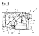
- FIG. 5 of the drawing shows an exemplary embodiment of the device 1, in which a transverse conveyor belt 135 is provided instead of the conveying channels and the discharge screws therein, as were explained with reference to FIGS. 1 and 2.
- This cross conveyor belt 135 extends over the entire width of the device 1, i.e. in Figure 5 perpendicular to the plane of the drawing.
- an opening 137 is recessed in the bottom 12 of the feed container 11, which opening can be optionally closed or released by means of a swivel flap 137 '.
- the cross conveyor belt 135 is preferably equipped with a switchable drive, so that either left or right conveyance by means of the cross conveyor belt 135 is made possible.
- An actuating element is merely indicated at 138 for adjusting the pivoting flap 137 ', which can be a hydraulically actuated piston-cylinder arrangement or an actuating lever mechanism or a cable-spring arrangement.
- a wiping grate 139 is inserted into the opening 137, which here consists of a plurality of strips arranged parallel to one another and next to one another, which are connected, preferably screwed or welded, to the base 12 of the container 11.
- the edge of the strips of the wiping grate 139 facing the arms 31 is made concave.
- the strips of the scraper grate are attached so that they are spaced apart so that small-scale feed, such as corn silage or beer spent grains, is dosed, i.e. can only pass through the opening 137 in small quantities.
- the feed is conveyed through the opening 137 by the tips 32 of the arms 31 passing by.
- a larger or smaller number of strips with a correspondingly larger or smaller mutual distance can be provided on the wiping grate 139 in which Practice, for example, between seven and three strips.
- the scraper grate 139 can also be designed as an exchangeable component in order to enable a quick change.
Landscapes
- Life Sciences & Earth Sciences (AREA)
- Environmental Sciences (AREA)
- Birds (AREA)
- Animal Husbandry (AREA)
- Biodiversity & Conservation Biology (AREA)
- Apparatuses For Bulk Treatment Of Fruits And Vegetables And Apparatuses For Preparing Feeds (AREA)
Abstract
Description
Die Erfindung betrifft eine Vorrichtung für die Entnahme, Zubereitung und Verteilung von Viehfutter, gemäß dem Oberbegriff des Anspruches 1.The invention relates to a device for the removal, preparation and distribution of cattle feed, according to the preamble of claim 1.
Eine Vorrichtung der genannten Art ist aus der NL-OS 90 00 682 bekannt. Bei dieser bekannten Vorrichtung ist der Schneidschild starr an dem vorderen Ende des Auslegerarmes angeordnet. Der Auslegerarm selbst ist als Teleskoparm ausgebildet und längenveränderlich. Als Mischorgan sind bei dieser Vorrichtung zwei in Querrichtung des Futterbehälters nebeneinander angeordnete, um zwei parallele, in Längsrichtung der Vorrichtung verlaufende Achsen drehbare Mischflügel vorgesehen. Die beiden Flügel drehen sich in einander entgegengesetzter Richtung, wobei sich die Drehbereiche überschneiden, so daß eine intensive Mischung des Futters erreicht wird. Gleichzeitig sorgen die Flügel für eine Förderung des aufbereiteten Futters zu zwei Austragschnecken, mit denen wahlweise das Futter nach links oder rechts ausgetragen werden kann.A device of the type mentioned is known from NL-OS 90 00 682. In this known device, the cutting blade is rigidly arranged at the front end of the extension arm. The cantilever arm itself is designed as a telescopic arm and is variable in length. In this device, two mixing vanes are arranged as juxtaposed in the transverse direction of the feed container and rotatable about two parallel axes running in the longitudinal direction of the device. The two wings rotate in opposite directions, the areas of rotation overlap so that an intensive mixing of the feed is achieved. At the same time, the blades ensure that the processed feed is conveyed to two discharge screws, with which the feed can either be discharged to the left or right.
Als nachteilig wird bei der bekannten Vorrichtung angesehen, daß die Ausführung mit einem teleskopierbaren Auslegerarm konstruktiv sehr aufwendig ist und das Einladen von Futter in den Futterbehälter hiermit relativ umständlich vonstatten geht. Außerdem verbleiben aufgrund dieser Konstruktion größere nicht durchmischte, nicht austragbare Futtermengen innerhalb des Futtermittelbehälters, was zusätzliche Handarbeit erforderlich macht. Mit den beiden Rührflügeln wird zwar eine gute Futterdurchmischung erreicht, jedoch können diese nicht für eine wirkungsvolle Zerkleinerung von langfaserigem Futter, z.B. Grassilage, sorgen. Unzerkleinerte langfaserige Futterbestandteile führen aber einerseits zu häufigeren betrieblichen Störungen an der Vorrichtung und sind andererseits hinsichtlich der Aufnahme und Verwertung durch das damit gefütterte Vieh ungünstig.A disadvantage of the known device is that the design with a telescopic extension arm is structurally very complex and the loading of feed into the feed container is thus relatively cumbersome takes place. In addition, due to this construction, larger amounts of non-mixed, non-disposable feed remain within the feed container, which requires additional manual work. A good forage mixing is achieved with the two agitator blades, but these cannot ensure effective comminution of long-fiber forage, eg grass silage. Non-shredded long-fiber feed components, on the one hand, lead to more frequent operational failures on the device and, on the other hand, are unfavorable in terms of absorption and utilization by the cattle fed with them.
Es stellt sich daher die Aufgabe, eine Vorrichtung der eingangs genannten Art zu schaffen, die die aufgeführten Nachteile vermeidet und die insbesondere neben einer guten Futterdurchmischung auch eine wirkungsvolle Zerkleinerung von langfaserigen Futterbestandteilen sicherstellt und bei der weiterhin das Befüllen und Entleeren des Futterbehälters einfach und zuverlässig erfolgt.It is therefore the task of creating a device of the type mentioned at the outset which avoids the disadvantages mentioned and which, in addition to good feed mixing, also ensures effective comminution of long-fiber feed constituents and in which the feed container is filled and emptied simply and reliably .
Die Lösung dieser Aufgabe gelingt erfindungsgemäß durch eine Vorrichtung der eingangs genannten Art mit den kennzeichnenden Merkmalen des Anspruches 1.This object is achieved according to the invention by a device of the type mentioned at the outset with the characterizing features of claim 1.
Mit der Erfindung wird erreicht, daß das Futter nicht nur intensiv gemischt, sondern auch mittels der Schneiden an den rotierenden Armen im Zusammenwirken mit den feststehenden Gegenschneiden im Behälter in gewünschter Weise durch Zerschneiden zerkleinert wird. Dabei bleibt die technische Konstruktion der Vorrichtung vergleichsweise einfach und für ihren Betrieb genügen ein relativ geringer Kraftaufwand und niedrige Drehzahlen der Welle. Das zerkleinerte Futter neigt im Gegensatz zu langfaserigem Gut kaum zum Anhängen an der Welle und den daran befestigten Armen, so daß eine praktisch vollständige Entleerung des Behälters ohne manuelle Eingriffe sichergestellt wird. Die Aufnahme und Verwertung des so aufbereiteten, nämlich kleingeschnittenen und homogen durchmischten Futters durch das damit gefütterte Vieh wird ebenfalls verbessert, wodurch ein günstigerer Futterverwertungsgrad erzielt wird.With the invention it is achieved that the feed is not only mixed intensively, but is also cut up in the desired manner by cutting by means of the cutting edges on the rotating arms in cooperation with the fixed counter cutting edges in the container. The technical construction of the device remains comparatively simple and a relatively low effort and low shaft speeds are sufficient for its operation. In contrast to long-fiber material, the shredded chuck hardly tends to be attached to the shaft and the arms attached to it, so that virtually complete emptying of the container is ensured without manual intervention becomes. The uptake and utilization of the thus prepared, namely finely chopped and homogeneously mixed feed by the cattle fed with it is also improved, as a result of which a more favorable degree of feed utilization is achieved.
Bevorzugt ist lediglich eine einzelne, horizontal quer durch den Futterbehälter verlaufende Welle vorgesehen, was bei Erfüllung aller vorgesehenen Funktionen eine einfache Konstruktion der Vorrichtung ermöglicht.Preferably, only a single shaft running horizontally across the feed container is provided, which enables a simple construction of the device when all the functions provided are fulfilled.
Bevorzugte Ausgestaltungen und Weiterbildungen der Schneiden und Gegenschneiden sind in den Ansprüchen 3 bis 5 angegeben, wobei insbesondere eine gute Schneidwirkung nach Art von Scheren erreicht wird.Preferred refinements and developments of the cutting and counter cutting are specified in
Hinsichtlich des Schneidschildes der Vorrichtung schlägt die Erfindung vor, daß der Schneidschild um eine nahe dessen oberer Kante verlaufende Achse relativ zum Auslegearm verschwenkbar ist. Durch diese Ausgestaltung kann der Schneidschild in Abhängigkeit von der jeweiligen Entnahmesituation, insbesondere der Entnahmehöhe am Silo, passend eingestellt werden. Außerdem kann der Schneidschild dazu benutzt werden, das ausgeschnittene Futter in das Innere des Futterbehälters zu schieben. In der abgesenkten und nach innen verschwenkten Stellung bildet der Schneidschild dann die Rückwand des Futterbehälters und schließt diesen nach hinten hin ab. Damit sind auch Transporte von Futter mit der Vorrichtung möglich, ohne daß Futterverluste auftreten.With regard to the cutting blade of the device, the invention proposes that the cutting blade can be pivoted relative to the extension arm about an axis running near its upper edge. With this configuration, the cutting blade can be adjusted appropriately depending on the particular removal situation, in particular the removal height on the silo. The cutting blade can also be used to push the cut feed into the interior of the feed container. In the lowered and inwardly pivoted position, the cutting plate then forms the rear wall of the feed container and closes it off towards the rear. This means that feed can also be transported with the device without loss of feed.
Bevorzugte Schneidmittel für den Schneidschild sind im Anspruch 8 angegeben.Preferred cutting means for the cutting blade are specified in claim 8.
Durch die Ausgestaltung des Bodens des Futterbehälters nach dem Anspruch 9 wird erreicht, daß eine einfache Schwenkbewegung schon das Futter vollständig erfaßt und in das Innere des Futterbehälters bewegt.The design of the bottom of the feed container according to claim 9 ensures that a simple swivel movement already completely detects the feed and moved inside the feed container.
In ähnlicher Weise ist vorgesehen, daß zumindest der Boden des Futterbehälters in dem von dem Misch- und Zerkleinerungsorgan überstreichbaren Bereich als Zylindermantelabschnitt ausgebildet ist, dessen Radius im wesentlichen dem maximalen Radius des Misch- und Zerkleinerungsorgans zuzüglich eines Freigangmaßes entspricht. Hierdurch werden Toträume innerhalb des Futterbehälters vermieden, so daß sämtliche Futterbestandteile, die sich im Behälter befinden, in den Misch- und Zerkleinerungsvorgang einbezogen werden.Similarly, it is provided that at least the bottom of the feed container is designed as a cylinder jacket section in the area that can be covered by the mixing and comminuting member, the radius of which essentially corresponds to the maximum radius of the mixing and comminuting member plus a clearance dimension. In this way, dead spaces within the feed container are avoided, so that all feed components which are in the container are included in the mixing and comminution process.
Ergänzend kann auch der Schneidschild an seiner dem Behälterinneren zugewandten Seite dieser zuvor erwähnten Zylindermantelform angepaßt sein, wodurch sich bei geschlossenem Zustand des Behälters eine Form ergibt, die zumindest in der unteren Hälfte zylindermantelförmig ist. Zusätzlich kann die dem Schneidschild gegenüberliegende Stirnwand des Futterbehälters in diese Zylindermantelform noch wenigstens teilweise einbezogen sein.In addition, the cutting plate on its side facing the interior of the container can also be adapted to this cylinder jacket shape mentioned above, which results in a shape when the container is closed, which is cylindrical jacket-shaped at least in the lower half. In addition, the end wall of the feed container opposite the cutting shield can also be at least partially included in this cylindrical jacket shape.
Weiterhin kann an dem Auslegerarm oder den Auslegerarmen ein in dessen/deren abgesenkter Stellung den Futterbehälter nach oben hin abdeckender gitter- oder plattenförmiger Deckel angeordnet sein, wodurch in abgesenktem und nach innen verschwenktem Zustand von Auslegerarm und Schneidschild ein allseitig geschlossener Futterbehälter gebildet wird. Insbesondere bei lockeren Futtermitteln, wie Heu oder Gras, wird durch den Deckel verhindert, daß das Futter sich nach oben hin aus dem Eingriffsbereich des Misch- und Zerkleinerungsorgans entfernen kann.Furthermore, a lattice or plate-shaped cover covering the feed container upward in its / its lowered position can be arranged on the extension arm or the extension arms, whereby a closed feed container is formed on all sides in the lowered and pivoted-in state of the extension arm and cutting blade. In particular in the case of loose feedstuffs, such as hay or grass, the cover prevents the feed from being able to move upward out of the area of engagement of the mixing and comminuting member.
Bevorzugte Ausgestaltungen der für den seitlichen Austrag des aufbereiteten Futters vorgesehenen Teile der Vorrichtung sind in den Ansprüchen 13 bis 18 dargelegt. Diese Ausgestaltungen ermöglichen eine wahlweise nach links oder rechts erfolgende Ausgabe des Futters, wobei eine Ausgabe zweckmäßig erst erfolgt, nachdem bei noch verschlossenem Behälter eine ausreichende Mischung und Zerkleinerung vorgenommen wurde. Im Zusammenhang hiermit sind die das Misch- und Zerkleinerungsorgan bildenden Arme auf ihrer Welle zweckmäßig so winkelversetzt zueinander angeordnet, daß sich eine gewisse seitliche Förderwirkung, je nach Drehrichtung der Welle zu der einen oder anderen Seite des Behälters, ergibt. Durch Wahl der Drehrichtung der Welle mit den Armen kann dann eine Zuförderung des Futters in den linken oder den rechten Teil des Behälters bewirkt werden, was vorteilhaft ist, wenn zwei getrennte Öffnungen im Behälterboden vorhanden sind. Außerdem wird durch den Versatz ein gleichmäßiger Kraftbedarf im Verlauf einer Umdrehung der Welle erreicht. Die Zahl der Arme an der Welle richtet sich im wesentlichen nach der Breite des Futterbehälters; sie liegt bevorzugt zwischen fünf und fünfzehn. Der Abstreifrost in der Öffnung sorgt dafür, daß Futter mit einem hohen Anteil an feinteiligen Bestandteilen, wie Maissilage oder Biertreber, nur dosiert durch die Öffnung hindurchtreten kann und so auch gleichmäßig durch das Querförderband ausgetragen wird.Preferred embodiments of the parts of the device provided for the lateral discharge of the processed feed are set out in
Um die Vorrichtung gemäß der Erfindung möglichst kostengünstig und nutzbringend einsetzen zu können, ist vorgesehen, daß diese als von einer Zugmaschine oder einem Traktor ziehbarer und betätigbarer Anhänger mit zwei Laufrädern und einer Zugdeichsel ausgeführt ist und daß zumindest der Behälter zwischen den an in Längsrichtung verlaufenden Schwingen angebrachten Rädern zur Futteraufnahme bis auf Bodenniveau absenkbar ist. Umgekehrt kann entsprechend der Behälter in eine bestimmte Höhe angehoben werden, so daß auch mehrere Meter hohe Silos bei dem Ausschneiden von Futter keine Probleme bereiten. Alternativ kann die Vorrichtung auch als selbstfahrendes Fahrzeug mit wenigstens drei Rädern, einem eigenen Antriebsmotor und Lenkung sowie Führerstand ausgeführt sein.In order to be able to use the device according to the invention as inexpensively and as profitably as possible, it is provided that it is designed as a trailer that can be pulled and actuated by a tractor or a tractor, with two wheels and a drawbar, and that at least the container is located between the wings running in the longitudinal direction attached wheels for feed intake can be lowered to ground level. Conversely, the container can be raised to a certain height, so that even silos several meters high pose no problems when cutting out forage. Alternatively, the device can also be used as a self-driving vehicle with at least three wheels and its own drive motor and steering and driver's cab.
Alternativ zu der vorangehend beschriebenen Ausführung kann die Vorrichtung auch als von einem Radlader oder einem Schlepper an dessen Hebeorganen tragbares Anbaugerät ausgeführt sein. In dieser Ausführung benötigt die Vorrichtung keine Räder und keine Deichsel, sondern ist vorzugsweise mit Kupplungsorganen, die zu dem die Vorrichtung tragenden Fahrzeug passen, ausgestattet, z.B. mit einer bekannten Dreipunktkupplung oder einem Frontladeradapter.As an alternative to the embodiment described above, the device can also be designed as an attachment which can be carried by a wheel loader or a tractor on the lifting members of the latter. In this embodiment, the device does not require wheels or a drawbar, but is preferably equipped with coupling elements that match the vehicle carrying the device, e.g. with a known three-point hitch or a front loader adapter.
Zweckmäßig sind die drehbaren Teile der Vorrichtung durch einen Zapfwellenantrieb oder durch Hydromotoren antreibbar und die heb- und senkbaren und die verschwenkbaren Teile der Vorrichtung durch hydraulische Kolben-Zylinder-Einheiten betätigbar. Die genannten Antriebs- und Betätigungseinrichtungen sind problemlos handhabbar und können bei Ausführung der Vorrichtung als Anhänger von der Zugmaschine oder dem Traktor aus durch deren Hydraulikanlage versorgt werden. Außerdem können damit die benötigten, teilweise relativ großen Kräfte ohne weiteres erzeugt werden.The rotatable parts of the device can expediently be driven by a PTO drive or by hydraulic motors, and the parts that can be raised, lowered and swiveled can be actuated by hydraulic piston-cylinder units. The drive and actuating devices mentioned are easy to handle and can be supplied from the tractor or the tractor by their hydraulic system when the device is designed as a trailer. In addition, the required, sometimes relatively large forces can be easily generated.
Um dem Benutzer der Vorrichtung eine möglichst genaue Kenntnis von der Menge des aufgenommenen Futters sowie gegebenenfalls der Mengenanteile von miteinander zu vermischenden, unterschiedlichen Futtersorten zu geben, wird vorgeschlagen, daß die Vorrichtung mit einer integrierten Wägeeinrichtung ausgebildet ist. Hierzu ist bevorzugt vorgesehen, daß an Abstützpunkten der beiden Schwingen und der Deichsel oder der Kupplungsorgane jeweils ein elektrisches oder elektronisches Lastaufnahmeelement, wie es an sich bekannt ist, angeordnet ist und daß diese Lastaufnahmeelemente mit einer an sich ebenfalls bekannten Auswerte- und Gewichtsanzeigeeinheit verbunden sind. Mit dieser Einrichtung kann unmittelbar nach der Futteraufnahme eine Wägung und damit eine Mengenbestimmung des im Behälter befindlichen Futters durchgeführt werden. Dies erlaubt genau dosierte Futterzubereitungen und -zuteilungen und damit einen besonders wirtschaftlichen Futtereinsatz.In order to provide the user of the device with the most precise knowledge possible of the amount of feed consumed and, if appropriate, of the proportions of different types of feed to be mixed with one another, it is proposed that the device be designed with an integrated weighing device. For this purpose, it is preferably provided that an electrical or electronic load-bearing element, as is known per se, is arranged at support points of the two rockers and the drawbar or the coupling members, and that these load-bearing elements are connected to an evaluation and weight display unit which is also known per se. With this facility you can immediately after the feed intake, a weighing and thus a quantity determination of the feed in the container can be carried out. This allows precisely metered feed preparations and allocations and thus a particularly economical use of feed.
Ein Ausführungsbeispiel der Erfindung wird im folgenden anhand einer Zeichnung erläutert. Die Figuren der Zeichnung zeigen:
- Figur 1
- die Vorrichtung in Seitenansicht in einem ersten Betriebszustand,
Figur 2- die Vorrichtung aus Figur 1 in einem zweiten Betriebszustand,
Figur 3- ein Detail eines Misch- und Zerkleinerungsorgans der Vorrichtung in Seitenansicht, teils im Vertikalschnitt,
- Figur 4
- das Detail des Misch- und Zerkleinerungsorgans gemäß
Figur 3 in Draufsicht und - Figur 5
- die Vorrichtung in einer zweiten Ausführung, im Ausschnitt in einer der Figur 1 entsprechenden Darstellung.
- Figure 1
- the device in side view in a first operating state,
- Figure 2
- 1 in a second operating state,
- Figure 3
- 1 shows a detail of a mixing and comminuting member of the device in a side view, partly in vertical section,
- Figure 4
- the detail of the mixing and crushing element according to Figure 3 in plan view and
- Figure 5
- the device in a second embodiment, in a detail in a representation corresponding to Figure 1.
Wie die Figur 1 der Zeichnung zeigt, ist das hier dargestellte Ausführungsbeispiel der Vorrichtung 1 als von einem Traktor oder einer Zugmaschine zu ziehender Anhänger mit einer Deichsel 18 und Rädern 16 ausgeführt. Den tragenden Teil der Vorrichtung 1 bildet ein Tragrahmen 10, der in üblicher Weise aus verschiedenen Profilen zusammengesetzt, vorzugsweise zusammengeschweißt ist. Den zentralen Teil der Vorrichtung 1 bildet ein Futterbehälter 11, der nach unten hin von einem Boden 12, 12', nach vorne hin, d.h. in der Zeichnung nach rechts, von einer Stirnwand 13 und zu den Seiten hin durch Seitenwände 13' begrenzt ist. Die Stirnwand 13 verläuft in ihrem oberen Teil schräg nach innen und geht an ihrem oberen Ende in einen Deckel 13'' über, der als Gitter- oder Blechplatte ausgebildet ist.As FIG. 1 of the drawing shows, the exemplary embodiment of the device 1 shown here is designed as a trailer to be pulled by a tractor or a tractor with a
Nach hinten hin, d.h. in der Zeichnung nach links, ist der Futterbehälter 11 in dem in Figur 1 gezeigten Betriebszustand der Vorrichtung 1 durch einen Schneidschild 2 verschlossen. Dieser Schneidschild 2 ist an einem Paar von über den Futterbehälter 11 verlaufenden Auslegerarmen 23, an denen auch der Deckel 13'' angebracht ist, um eine Schwenkachse 21 verschwenkbar gehaltert. Zur Ausführung der Schwenkbewegung des Schneidschildes 2 um die Schwenkachse 21 dient mindestens eine Kolben-Zylinder-Einheit 22 im oberen Teil der Vorrichtung 1. Die Auslegearme 23 sind ihrerseits zusammen mit dem Schneidschild um eine weitere Schwenkachse 24 mittels jeweils einer Kolben-Zylinder-Einheit 25 heb- und senkbar. Beide Schwenkachsen 21, 24 verlaufen in einer im wesentlichen horizontalen Richtung quer zur Längsachse der Vorrichtung 1, d.h. senkrecht zur Zeichnungsebene.Backwards, i.e. to the left in the drawing, the
Im Inneren des Futterbehälters 11 ist ein Misch- und Zerkleinerungsorgan 3 angeordnet. Dieses besteht aus einer einzelnen Welle 30, an der winkelversetzt mehrere, hier insgesamt elf Arme 31 angebracht sind, wobei der erste und der elfte Arm deckungsgleich liegen. Die Welle 30 mit den Armen 31 ist durch einen Antrieb 34 über einen Zapfwellenanschluß 34' in Drehung versetzbar. Die Enden der Arme 31 tragen nach außen hin spitz zulaufende, dreieckförmige Schneiden 32, die hier als Doppelschneiden ausgebildet sind, wodurch eine Schneidwirkung in beiden Drehrichtungen der Welle 30 erzielt wird. Die Schneiden 32 wirken mit feststehenden Gegenschneiden 33, die im Futterbehälter 11 angeordnet sind, zusammen, wobei die Schneidengeometrie beispielsweise der von Blechscheren ähneln kann. Bei dem hier gezeigten Ausführungsbeispiel sind diese Gegenschneiden 33 als in vertikaler Richtung verlaufende, annähernd dreieckförmige Blechplatten ausgebildet, die im Übergangsbereich zwischen dem Boden 12 und der Stirnwand 13 des Futterbehälters 11 angebracht sind. Zweckmäßig sind sowohl die Schneiden 32 an den Armen 31 als auch die Gegenschneiden 33 an dem Futterbehälter 11 lösbar angebracht, z.B. mittels Verschraubungen, um einen Austausch oder einen vorübergehenden Ausbau zwecks Nachbearbeitung der Schneiden oder Erneuerung einzelner Schneiden zu ermöglichen.A mixing and
Unterhalb des Bodens 12 des Futterbehälters 11 liegen zwei in Flucht zueinander ausgerichtete Förderkanäle 36, von denen hier der vordere sichtbar ist. In jedem Förderkanal 36 liegt eine Austragschnecke 35. Jeder der beiden Förderkanäle 36 ist über eine Öffnung 37 im Boden 12 mit dem Futterbehälter 11 verbunden, wobei mittels je eines Schiebers 37' die Öffnung 37 wahlweise verschließbar oder freigebbar ist.Below the bottom 12 of the
Die schon erwähnten Räder 16, von denen hier das vordere sichtbar ist, sind an in Längsrichtung der Vorrichtung 1 verlaufenden Schwingen 15 gelagert, die sich einerseits unmittelbar verschwenkbar an der Vorrichtung 1 unterhalb des Bodens 12 des Futterbehälters 11 abstützen und die an ihrem das Rad 16 tragenden Ende über eine Kolben-Zylinder-Einheit 17 mit einem weiteren Punkt der Vorrichtung 1 seitlich am oberen Teil des Behälters 11 verbunden sind. In dem in Figur 1 gezeigten Betriebszustand der Vorrichtung 1 ist die Kolbenstange der Kolben-Zylinder-Einheit 17 vollständig ausgefahren, wodurch die Vorrichtung 1 eine angehobene Stellung einnimmt. In dieser angehobenen Stellung der Vorrichtung 1 und mit nach unten und innen verschwenktem Schneidschild 2 kann die Vorrichtung 1 wie ein Anhänger von einer Zugmaschine oder einem Schlepper verfahren werden.The already mentioned
Figur 2 der Zeichnung zeigt die Vorrichtung 1 in gleicher Darstellungsweise wie in Figur 1 in einem Betriebszustand während der Aufnahme von Futter in den Futterbehälter 11. Die Vorrichtung 1 ist hierzu durch Einfahren der Kolbenstange der Kolben-Zylinder-Einheit 17 in eine abgesenkte Stellung gebracht, wodurch eine Absetzplatte 14, die den unteren hinteren Teil der Vorrichtung 1 bildet, auf den vorhandenen Untergrund, z.B. die Bodenfläche eines Fahrsilos, abgesenkt ist. An ihrem Stirnende ist die Absetzplatte 14 mit einer Ladekante 14' ausgebildet, die spitz-keilförmig ist und mit der die Absetzplatte 14 durch Rückwärtsbewegen der Vorrichtung 1 in einen Futtermittelvorrat eingestoßen werden kann. Die Deichsel 18 nimmt demzufolge eine schräg nach oben verlaufende Lage ein.FIG. 2 of the drawing shows the device 1 in the same representation as in FIG. 1 in an operating state during the intake of feed into the
Weiterhin ist zur Aufnahme von Futter der Schneidschild 2 mittels Anhebens der Auslegearme 21 nach oben hin bewegt. Hierzu ist die Kolbenstange der Kolben-Zylinder-Einheit 25 in ihre ausgefahrene Stellung gebracht worden. Aus seiner angehobenen Stellung kann dann der Schneidschild 2 von oben nach unten verfahren werden und dabei Futter aus der Stirnfläche eines Futtermittelvorrats ausschneiden. Hierzu sind an der Unterkante des Schneidschildes 2 Schneidmittel 20 vorgesehen, z.B. an sich bekannte oszillierende Schneidmesser, die den gewünschten Schnitt durch den Futtermittelvorrat ausführen. Zusätzlich sind seitliche drehantreibbare Schneidscheiben 20' vorgesehen. Durch wiederholtes Anheben und schneidendes Absenken des Schneidschildes unter stufenweiser Vorschwenkung des unteren Endes des Schneidschildes, wie in der Zeichnung durch gestrichelte Bewegungslinien angedeutet, können nach und nach die benötigten Futtermengen ausgeschnitten und in das Innere des Futterbehälters 11 befördert werden. Zum Abschluß des Beladevorganges wird der Schneidschild 2 in seiner abgesenkten Stellung von außen langsam nach innen verschwenkt, wobei schon der Mischvorgang durch Drehen des Misch- und Zerkleinerungsorgans 3, vorzugsweise gegen den Uhrzeigersinn in der Figur 2, beginnen kann, wodurch die zugeführten Futterpakete oder -brocken umgehend zerkleinert werden. Durch Anheben der Vorrichtung 1 mittels Betätigung der Kolben-Zylinder-Einheit 17 wird die Vorrichtung 1 wieder in einen verfahrbaren Zustand überführt und kann anschließend beispielsweise in einen Stallgang verfahren werden.Furthermore, the
Nach einer ausreichend langen Mischung und Zerkleinerung des im Futterbehälter 11 befindlichen Futters mittels des Misch- und Zerkleinerungsorgans 3 kann das Futter mittels der einen der beiden Austragschnecken 35 wahlweise zur linken oder rechten Seite der Vorrichtung 1 unter stetiger Vorwärtsbewegung derselben ausgetragen werden. Die Futtermenge, die pro Zeiteinheit ausgetragen wird, kann durch die Fahrgeschindigkeit oder auch durch den Öffnungsgrad des Schiebers 37' in der Öffnung 37 beeinflußt werden.After a sufficiently long mixing and comminution of the feed located in the
Wie sowohl aus Figur 1 als auch aus Figur 2 ersichtlich ist, ist der Boden 12, 12' des Futterbehälters 11 in seinem vorderen, d.h. in der Zeichnung rechten Teil 12 dem Radius des Misch- und Zerkleinerungsorgans 3 und in seinem hinteren, d.h. in der Zeichnung linken Teil 12' dem Schwenkradius des Schneidschildes 2 in dessen abgesenkter Stellung angepaßt. Außerdem ist der Schneidschild 2 in seinem unteren Teil ebenfalls dem Radius des Misch- und Zerkleinerungsorgans 3 angepaßt. Nach oben hin wird durch den Deckel 13'' ein Ausweichen und Auswerfen von Futter verhindert. Hierdurch werden Toträume im Futterbehälter 11 vermieden und die gesamte darin befindliche Futtermenge wird dem Misch- und Zerkleinerungsvorgang unterzogen.As can be seen from both Figure 1 and Figure 2, the bottom 12, 12 'of the
Anhand von Figur 3 und 4 der Zeichnung wird die Funktion des Misch- und Zerkleinerungsorgans 3 besonders deutlich. Die Figuren 3 und 4 zeigen lediglich einen der bei dem in Figur 1 und 2 gezeigten Ausführungsbeispiel insgesamt zehn Arme 31, der hier auf der Welle 30 in geeigneter Weise verdrehfest montiert ist. Das äußere Ende des Armes 31 ist mit zwei Schneiden 32, 32' ausgebildet, die mit einer Gegenschneide 33, die feststehend am Boden 12 des Futterbehälters 11 angebracht ist, zusammenwirken. Hierzu ist, wie besonders deutlich aus Figur 4 der Zeichnung hervorgeht, das äußere Ende des Armes 31 mit einem Durchtrittsschlitz für die feststehende Gegenschneide 33 ausgebildet. Je Arm 31 wirken somit zwei Schneiden 32 - bzw. 32' bei umgekehrter Drehrichtung - mit der feststehenden Gegenschneide 33 zusammen, um insbesondere langfaseriges Futter, wie Grassilage oder Heu, zu zerschneiden und zu zerkleinern und außerdem zu vermischen, falls unterschiedliche Futtersorten in den Behälter gefüllt wurden.With reference to Figures 3 and 4 of the drawing, the function of the mixing and
Figur 5 der Zeichnung schließlich zeigt ein Ausführungsbeispiel der Vorrichtung 1, bei dem anstelle der Förderkanäle und der darin liegenden Austragsschnecken, wie sie anhand von Figur 1 und 2 erläutert wurden, ein Querförderband 135 vorgesehen ist. Dieses Querförderband 135 verläuft über die gesamte Breite der Vorrichtung 1, d.h. in Figur 5 senkrecht zur Zeichnungsebene. Oberhalb des Querförderbandes 135 ist in dem Boden 12 des Futterbehälters 11 eine Öffnung 137 ausgespart, die mittels einer Schwenkklappe 137' wahlweise verschließbar oder freigebbar ist.Finally, FIG. 5 of the drawing shows an exemplary embodiment of the device 1, in which a
Befindet sich die Schwenkklappe 137' in ihrer Schließstellung, so bildet diese einen Teil des Bodens 12; wenn die Schwenkklappe 137' sich in ihrer Öffnungsstellung befindet, die in der Figur 5 dargestellt ist, wird die Öffnung 137 freigegeben und Futter kann aus dem Inneren des Behälters 11 nach unten fallen und so auf das Querförderband 135 gelangen. Das Querförderband 135 ist vorzugsweise mit einem umschaltbaren Antrieb ausgestattet, so daß wahlweise eine Förderung nach links oder rechts mittels des Querförderbandes 135 ermöglicht wird.If the swivel flap 137 'is in its closed position, it forms part of the
Zur Verstellung der Schwenkklappe 137' ist bei 138 ein Betätigungsorgan lediglich angedeutet, wobei es sich hier um eine hydraulisch betätigbare Kolben-Zylinder-Anordnung oder ein Betätigungs-Hebelwerk oder eine Seilzug-Feder-Anordnung handeln kann.An actuating element is merely indicated at 138 for adjusting the pivoting flap 137 ', which can be a hydraulically actuated piston-cylinder arrangement or an actuating lever mechanism or a cable-spring arrangement.
Die Schwenkklappe 137' kann so ausgeführt sein, daß sie über einen Teil oder über die Gesamtheit der Breite des Bodens 12 des Behälters 11 reicht; auch können zwei oder mehr Schwenkklappen 137' nebeneinander vorgesehen sein.The pivoting flap 137 'can be designed so that it extends over part or all of the width of the bottom 12 of the
Im dargestellten Ausführungsbeispiel ist in die Öffnung 137 ein Abstreifrost 139 eingesetzt, der hier aus mehreren parallel zueinander und nebeneinander angeordneten Streifen besteht, die mit dem Boden 12 des Behälters 11 verbunden, bevorzugt verschraubt oder verschweißt, sind. Entsprechend dem zylindermantelförmigen Verlauf des Bodens 12 ist die den Armen 31 zugewandte Kante der Streifen des Abstreifrostes 139 konkav verlaufend ausgeführt. Die Streifen des Abstreifrostes sind so voneinander beabstandet angebracht, daß kleinteiliges Futter, wie Maissilage oder Biertreber, dosiert, d.h. lediglich in kleinen Mengen durch die Öffnung 137 hindurchtreten kann. Die Beförderung des Futters durch die Öffnung 137 wird dabei durch die vorbeilaufenden Spitzen bzw. Schneiden 32 der Arme 31 bewirkt.In the exemplary embodiment shown, a wiping
Je nach Art des überwiegend zu verarbeitenden Futters kann eine größere oder kleinere Anzahl von Streifen mit entsprechend größerem oder kleinerem gegenseitigen Abstand am Abstreifrost 139 vorgesehen werden, in der Praxis beispielsweise zwischen sieben und drei Streifen. Auch kann der Abstreifrost 139 als auswechselbares Bauteil ausgebildet sein, um eine schnelle Änderung zu ermöglichen.Depending on the type of feed to be processed predominantly, a larger or smaller number of strips with a correspondingly larger or smaller mutual distance can be provided on the wiping
Die in Figur 5 sichtbaren weiteren Teile der Vorrichtung 1 entsprechen in ihrer Bezifferung den in den Figuren 1 bis 4 schon erläuterten Teilen.The other parts of the device 1 visible in FIG. 5 correspond in their numbers to the parts already explained in FIGS. 1 to 4.
Claims (23)
dadurch gekennzeichnet,
daß das Misch- und Zerkleinerungsorgan (3) aus mindestens einer durch den Futterbehälter (11) verlaufenden drehantreibbaren Welle (30) besteht, daß an der Welle (30) mehrere in radialer Richtung weisende, gegeneinander winkelversetzte Arme (31) angeordnet sind, daß jeweils der äußere Endbereich der Arme (31) mit mindestens einer Schneide (32) ausgebildet ist und daß innenseitig am Futterbehälter (11) feststehende, mit den Schneiden (32) an den Armen (31) zusammenwirkende Gegenschneiden (33) angeordnet sind.Device for the removal, preparation and distribution of cattle feed, in particular silage, with a feed container (11) with a cutting plate (2) arranged on the rear side thereof, which is held on at least one lifting and lowering arm (23), the cutting plate (2) is equipped on its lower edge with cutting means (20) for cutting out feed from a feed stock, in particular from a silo, and in its lowered position closes the feed container (11) towards the rear, with at least one arranged in the feed container (11) rotatable mixing and comminuting element (3) and with at least one discharge device at the bottom in or below the feed container (11) for a lateral discharge of the prepared feed,
characterized,
that the mixing and comminuting member (3) consists of at least one shaft (30) which can be driven in rotation by the feed container (11), that on the shaft (30) a plurality of arms (31) pointing in the radial direction and mutually angularly offset are arranged, in each case that the outer end region of the arms (31) is formed with at least one cutting edge (32) and that counter-cutting edges (33) which are fixed on the inside of the feed container (11) and interact with the cutting edges (32) on the arms (31).
Applications Claiming Priority (2)
| Application Number | Priority Date | Filing Date | Title |
|---|---|---|---|
| DE4300148A DE4300148C2 (en) | 1993-01-08 | 1993-01-08 | Device for taking, preparing and distributing animal feed |
| DE4300148 | 1993-01-08 |
Publications (2)
| Publication Number | Publication Date |
|---|---|
| EP0606087A1 true EP0606087A1 (en) | 1994-07-13 |
| EP0606087B1 EP0606087B1 (en) | 1996-04-24 |
Family
ID=6477773
Family Applications (1)
| Application Number | Title | Priority Date | Filing Date |
|---|---|---|---|
| EP94100172A Expired - Lifetime EP0606087B1 (en) | 1993-01-08 | 1994-01-07 | Device for taking out, preparing and distributing of animal fodder |
Country Status (2)
| Country | Link |
|---|---|
| EP (1) | EP0606087B1 (en) |
| DE (2) | DE4300148C2 (en) |
Cited By (6)
| Publication number | Priority date | Publication date | Assignee | Title |
|---|---|---|---|---|
| EP0833558A1 (en) | 1995-04-20 | 1998-04-08 | Salford Engineering Limited | Mixing and dispensing apparatus |
| WO1998057537A1 (en) * | 1997-06-16 | 1998-12-23 | Northington Limited | A mixing apparatus |
| EP0738464B1 (en) * | 1995-04-21 | 2001-08-29 | Trioliet Mullos B.V. | Device and method for collecting fodder |
| EP1232683A1 (en) * | 2001-02-16 | 2002-08-21 | CLAAS Selbstfahrende Erntemaschinen GmbH | Conveyor elements and shredder device for agricultural machine |
| NL1022678C2 (en) * | 2003-02-14 | 2004-08-17 | Trioliet Mullos | Method and device for retrieving a quantity of feed from a feed supply. |
| CN112931266A (en) * | 2021-01-27 | 2021-06-11 | 冯丽芳 | Automatic feeder of fodder for livestock breeding |
Families Citing this family (1)
| Publication number | Priority date | Publication date | Assignee | Title |
|---|---|---|---|---|
| CN113231167A (en) * | 2021-05-17 | 2021-08-10 | 盛越 | Pet feeding device |
Citations (4)
| Publication number | Priority date | Publication date | Assignee | Title |
|---|---|---|---|---|
| EP0014154A1 (en) * | 1979-01-29 | 1980-08-06 | S.A. AUDUREAU Société dite: | Towed implement for picking up and transporting materials |
| DE3313227A1 (en) * | 1983-04-13 | 1983-09-01 | B. Strautmann & Söhne GmbH u. Co, 4518 Bad Laer | Appliance for picking up, transporting and distributing silage fodder |
| WO1989002215A1 (en) * | 1987-09-08 | 1989-03-23 | Hammarstrand Per Aake | Straw cutter |
| EP0415466A1 (en) * | 1989-08-30 | 1991-03-06 | Litech B.V. | Apparatus for cutting silage from a silage supply |
Family Cites Families (5)
| Publication number | Priority date | Publication date | Assignee | Title |
|---|---|---|---|---|
| DE8401745U1 (en) * | 1984-01-21 | 1987-07-09 | De Dissel Beheer B.V., Aalten | Discharge and dosing device, especially for clump-forming feed such as grass silage or similar. |
| DE3837350A1 (en) * | 1987-12-03 | 1989-06-15 | Fortschritt Veb K | Comminutor for the chopping assembly of a field chopper |
| DE3936415A1 (en) * | 1989-11-02 | 1991-05-08 | Strautmann & Soehne | Implement for removing silage - incorporates oscillating blade and counter-blade |
| NL9002003A (en) * | 1990-03-22 | 1991-10-16 | Litech Bv | APPARATUS FOR MIXING AND / OR DOSED FEEDING OR THE LIKE. |
| NL9000682A (en) * | 1990-03-22 | 1991-10-16 | Litech Bv | Mixing and metering equipment e.g. for animal fodder - includes mixing chamber contg. one or mixing elements |
-
1993
- 1993-01-08 DE DE4300148A patent/DE4300148C2/en not_active Expired - Fee Related
-
1994
- 1994-01-07 EP EP94100172A patent/EP0606087B1/en not_active Expired - Lifetime
- 1994-01-07 DE DE59400221T patent/DE59400221D1/en not_active Expired - Fee Related
Patent Citations (4)
| Publication number | Priority date | Publication date | Assignee | Title |
|---|---|---|---|---|
| EP0014154A1 (en) * | 1979-01-29 | 1980-08-06 | S.A. AUDUREAU Société dite: | Towed implement for picking up and transporting materials |
| DE3313227A1 (en) * | 1983-04-13 | 1983-09-01 | B. Strautmann & Söhne GmbH u. Co, 4518 Bad Laer | Appliance for picking up, transporting and distributing silage fodder |
| WO1989002215A1 (en) * | 1987-09-08 | 1989-03-23 | Hammarstrand Per Aake | Straw cutter |
| EP0415466A1 (en) * | 1989-08-30 | 1991-03-06 | Litech B.V. | Apparatus for cutting silage from a silage supply |
Cited By (8)
| Publication number | Priority date | Publication date | Assignee | Title |
|---|---|---|---|---|
| EP0833558A1 (en) | 1995-04-20 | 1998-04-08 | Salford Engineering Limited | Mixing and dispensing apparatus |
| US5967433A (en) * | 1995-04-20 | 1999-10-19 | Salford Engineering Limited | Mixing and dispensing apparatus |
| EP0738464B1 (en) * | 1995-04-21 | 2001-08-29 | Trioliet Mullos B.V. | Device and method for collecting fodder |
| WO1998057537A1 (en) * | 1997-06-16 | 1998-12-23 | Northington Limited | A mixing apparatus |
| EP1232683A1 (en) * | 2001-02-16 | 2002-08-21 | CLAAS Selbstfahrende Erntemaschinen GmbH | Conveyor elements and shredder device for agricultural machine |
| NL1022678C2 (en) * | 2003-02-14 | 2004-08-17 | Trioliet Mullos | Method and device for retrieving a quantity of feed from a feed supply. |
| EP1452087A3 (en) * | 2003-02-14 | 2008-03-26 | Trioliet Mullos B.V. | Method and apparatus for removing a quantity of fodder from a stock thereof |
| CN112931266A (en) * | 2021-01-27 | 2021-06-11 | 冯丽芳 | Automatic feeder of fodder for livestock breeding |
Also Published As
| Publication number | Publication date |
|---|---|
| EP0606087B1 (en) | 1996-04-24 |
| DE4300148C2 (en) | 1994-11-10 |
| DE4300148A1 (en) | 1994-07-14 |
| DE59400221D1 (en) | 1996-05-30 |
Similar Documents
| Publication | Publication Date | Title |
|---|---|---|
| EP0047446A1 (en) | Apparatus for removing, loading, transporting, preparing and distributing fodder | |
| DE69903477T2 (en) | Trolley for tearing and mixing material for zoological applications | |
| DE1808969A1 (en) | Mixer | |
| DE69604397T2 (en) | DEVICE FOR QUANTITY AND DISPENSING PRODUCTS | |
| DE3529452A1 (en) | SPREADER | |
| DE2651268A1 (en) | MOVABLE MACHINE FOR REMOVING AND PROCESSING STORED FORAGE FROM A SILO | |
| DE1407674A1 (en) | Means for spreading or scattering any substance or material | |
| EP0606087B1 (en) | Device for taking out, preparing and distributing of animal fodder | |
| EP0134945B1 (en) | Apparatus for mixing and dosing solids | |
| DE2147280A1 (en) | Grist and mixing plant | |
| DE10206270B4 (en) | Device for mixing and discharging bulk material | |
| EP0061666B1 (en) | Pivoting blender for animal feed | |
| EP0176057A2 (en) | Chopper for organic material | |
| EP0699387A1 (en) | Mobile fodder mixing and distributing device | |
| DE69712224T2 (en) | CRUSHING DEVICE WITH SWIVELING RECEIVING MECHANISM | |
| EP0568961A2 (en) | Bale shredder | |
| DE69423711T2 (en) | Agricultural machine for the distribution of animal feed and / or straw bedding | |
| DE2536793C3 (en) | Device for removing, transporting and distributing silage feed from silos, rents or the like. (so-called silo cutter) | |
| DE2535701C3 (en) | Device for removing, transporting and distributing silage feed from silos, rents or the like. to feeding places (so-called silo cutter) | |
| DE2358817A1 (en) | MOBILE THINK SPREADER | |
| DE3007490A1 (en) | Lumpy fodder discharge and metering mechanism - has reversible auger and scraper shaft between hopper and openings | |
| DE69003747T2 (en) | Extractor and transport device. | |
| DE4121328C2 (en) | Transport and discharge device for a feed block | |
| DE69210851T2 (en) | Apparatus for cleaning or chopping or mixing or distributing material | |
| DE69522289T2 (en) | Trailer with snails for mixing, chopping and distributing animal feed |
Legal Events
| Date | Code | Title | Description |
|---|---|---|---|
| PUAI | Public reference made under article 153(3) epc to a published international application that has entered the european phase |
Free format text: ORIGINAL CODE: 0009012 |
|
| AK | Designated contracting states |
Kind code of ref document: A1 Designated state(s): AT BE CH DE DK ES FR GB GR IE IT LI LU MC NL PT SE |
|
| RBV | Designated contracting states (corrected) |
Designated state(s): BE DE DK FR GB IE IT LU NL |
|
| 17P | Request for examination filed |
Effective date: 19950110 |
|
| 17Q | First examination report despatched |
Effective date: 19950720 |
|
| GRAA | (expected) grant |
Free format text: ORIGINAL CODE: 0009210 |
|
| AK | Designated contracting states |
Kind code of ref document: B1 Designated state(s): BE DE DK FR GB IE IT LU NL |
|
| PG25 | Lapsed in a contracting state [announced via postgrant information from national office to epo] |
Ref country code: IT Free format text: LAPSE BECAUSE OF FAILURE TO SUBMIT A TRANSLATION OF THE DESCRIPTION OR TO PAY THE FEE WITHIN THE PRE;WARNING: LAPSES OF ITALIAN PATENTS WITH EFFECTIVE DATE BEFORE 2007 MAY HAVE OCCURRED AT ANY TIME BEFORE 2007. THE CORRECT EFFECTIVE DATE MAY BE DIFFERENT FROM THE ONE RECORDED.SCRIBED TIME-LIMIT Effective date: 19960424 Ref country code: GB Effective date: 19960424 Ref country code: FR Effective date: 19960424 Ref country code: DK Effective date: 19960424 |
|
| REG | Reference to a national code |
Ref country code: IE Ref legal event code: FG4D Free format text: 68120 |
|
| REF | Corresponds to: |
Ref document number: 59400221 Country of ref document: DE Date of ref document: 19960530 |
|
| EN | Fr: translation not filed | ||
| GBV | Gb: ep patent (uk) treated as always having been void in accordance with gb section 77(7)/1977 [no translation filed] |
Effective date: 19960424 |
|
| PG25 | Lapsed in a contracting state [announced via postgrant information from national office to epo] |
Ref country code: IE Free format text: LAPSE BECAUSE OF NON-PAYMENT OF DUE FEES Effective date: 19961107 |
|
| REG | Reference to a national code |
Ref country code: IE Ref legal event code: FD4D Ref document number: 68120 Country of ref document: IE |
|
| PG25 | Lapsed in a contracting state [announced via postgrant information from national office to epo] |
Ref country code: LU Free format text: LAPSE BECAUSE OF NON-PAYMENT OF DUE FEES Effective date: 19970131 |
|
| PLBE | No opposition filed within time limit |
Free format text: ORIGINAL CODE: 0009261 |
|
| STAA | Information on the status of an ep patent application or granted ep patent |
Free format text: STATUS: NO OPPOSITION FILED WITHIN TIME LIMIT |
|
| 26N | No opposition filed | ||
| PGFP | Annual fee paid to national office [announced via postgrant information from national office to epo] |
Ref country code: DE Payment date: 19971212 Year of fee payment: 5 Ref country code: BE Payment date: 19971212 Year of fee payment: 5 |
|
| PGFP | Annual fee paid to national office [announced via postgrant information from national office to epo] |
Ref country code: NL Payment date: 19980130 Year of fee payment: 5 |
|
| PG25 | Lapsed in a contracting state [announced via postgrant information from national office to epo] |
Ref country code: BE Free format text: LAPSE BECAUSE OF NON-PAYMENT OF DUE FEES Effective date: 19990131 |
|
| BERE | Be: lapsed |
Owner name: DE DISSEL BEHEER B.V. Effective date: 19990131 |
|
| PG25 | Lapsed in a contracting state [announced via postgrant information from national office to epo] |
Ref country code: NL Free format text: LAPSE BECAUSE OF NON-PAYMENT OF DUE FEES Effective date: 19990801 |
|
| PG25 | Lapsed in a contracting state [announced via postgrant information from national office to epo] |
Ref country code: DE Free format text: LAPSE BECAUSE OF NON-PAYMENT OF DUE FEES Effective date: 19991103 |