EP0605472B1 - Granulieren von schlacke - Google Patents
Granulieren von schlacke Download PDFInfo
- Publication number
- EP0605472B1 EP0605472B1 EP92919028A EP92919028A EP0605472B1 EP 0605472 B1 EP0605472 B1 EP 0605472B1 EP 92919028 A EP92919028 A EP 92919028A EP 92919028 A EP92919028 A EP 92919028A EP 0605472 B1 EP0605472 B1 EP 0605472B1
- Authority
- EP
- European Patent Office
- Prior art keywords
- trough
- enclosure
- granules
- atomiser
- granulator
- Prior art date
- Legal status (The legal status is an assumption and is not a legal conclusion. Google has not performed a legal analysis and makes no representation as to the accuracy of the status listed.)
- Expired - Lifetime
Links
Images

Classifications
-
- C—CHEMISTRY; METALLURGY
- C21—METALLURGY OF IRON
- C21B—MANUFACTURE OF IRON OR STEEL
- C21B3/00—General features in the manufacture of pig-iron
- C21B3/04—Recovery of by-products, e.g. slag
- C21B3/06—Treatment of liquid slag
- C21B3/08—Cooling slag
-
- B—PERFORMING OPERATIONS; TRANSPORTING
- B01—PHYSICAL OR CHEMICAL PROCESSES OR APPARATUS IN GENERAL
- B01J—CHEMICAL OR PHYSICAL PROCESSES, e.g. CATALYSIS OR COLLOID CHEMISTRY; THEIR RELEVANT APPARATUS
- B01J2/00—Processes or devices for granulating materials, e.g. fertilisers in general; Rendering particulate materials free flowing in general, e.g. making them hydrophobic
- B01J2/02—Processes or devices for granulating materials, e.g. fertilisers in general; Rendering particulate materials free flowing in general, e.g. making them hydrophobic by dividing the liquid material into drops, e.g. by spraying, and solidifying the drops
- B01J2/04—Processes or devices for granulating materials, e.g. fertilisers in general; Rendering particulate materials free flowing in general, e.g. making them hydrophobic by dividing the liquid material into drops, e.g. by spraying, and solidifying the drops in a gaseous medium
-
- C—CHEMISTRY; METALLURGY
- C21—METALLURGY OF IRON
- C21B—MANUFACTURE OF IRON OR STEEL
- C21B2400/00—Treatment of slags originating from iron or steel processes
- C21B2400/02—Physical or chemical treatment of slags
- C21B2400/022—Methods of cooling or quenching molten slag
- C21B2400/026—Methods of cooling or quenching molten slag using air, inert gases or removable conductive bodies
-
- C—CHEMISTRY; METALLURGY
- C21—METALLURGY OF IRON
- C21B—MANUFACTURE OF IRON OR STEEL
- C21B2400/00—Treatment of slags originating from iron or steel processes
- C21B2400/05—Apparatus features
- C21B2400/052—Apparatus features including rotating parts
-
- C—CHEMISTRY; METALLURGY
- C21—METALLURGY OF IRON
- C21B—MANUFACTURE OF IRON OR STEEL
- C21B2400/00—Treatment of slags originating from iron or steel processes
- C21B2400/05—Apparatus features
- C21B2400/052—Apparatus features including rotating parts
- C21B2400/054—Disc-shaped or conical parts for cooling, dispersing or atomising of molten slag rotating along vertical axis
-
- C—CHEMISTRY; METALLURGY
- C21—METALLURGY OF IRON
- C21B—MANUFACTURE OF IRON OR STEEL
- C21B2400/00—Treatment of slags originating from iron or steel processes
- C21B2400/05—Apparatus features
- C21B2400/066—Receptacle features where the slag is treated
- C21B2400/076—Fluidised bed for cooling
Definitions
- This invention relates to a method of, and apparatus for, granulating a molten material.
- the material may be a metal, such as iron; a metal oxide, such as titanium oxide; a non-metal, such as slag generated as a by-product of a metals production processs; or a mixture thereof.
- the invention is particularly applicable to the granulation of slag tapped from an iron blast furnace.
- the granulated slag can be used as a Portland cement substitute in the manufacture of concrete.
- GB-B-2148330 discloses an apparatus and method for the granulation of slag.
- the granulator includes a rotary atomiser located within an enclosure.
- the base of the enclosure is in the form of a hopper containing a fluidised bed.
- a stream of molten slag is poured on to the atomiser which is rotated at a speed such that the slag is ejected from the atomiser as a sheet or ribbon.
- Air jets from nozzles surrounding the atomiser impinge upon the sheet or ribbon and break it up into granules and impart an upward motion to them.
- the granules then fall towards the base of the enclosure where they pass through a countercurrent stream of secondary air and then enter into the fluidised bed.
- This apparatus and method suffer from the disadvantage of the need to provide the air jets which impinge upon the sheet or ribbon to break it up into granular form.
- a considerable input energy requirement is necessary to provide air jets of sufficient force to break up the sheet or ribbon of slag and provide upward motion to the granules.
- this form of granulator is unreliable because it depends on the granules rolling down the inner wall of the enclcsure to the exit point. If some granules stick to the wall, they prevent others from rolling down the wall and a build up of hardened granules on the wall soon occurs.
- a granulator of molten magnesium or its alloys to comprise a centrifugal granulator with a perforated sleeve and a cylindrical chamber for trapping granules formed from the molten metal upon it being flung out through the perforated sleeve.
- Within the chamber there is an annular trough for receiving the granules and the trough has at least one outlet opening and a rotatable ring having scrapers located in the trough. The ring is rotated to scrape the granules to the outlet opening.
- This arrangement may also suffer from the problem of granules sticking together in the trough. When the granules fall into the trough they may be only partially frozen and tend to stick to uncooled surfaces and to each other.
- An object of the present invention is to provide a method of, and apparatus for, granulating molten material in which the disadvantages of the prior art arrangements are overcome.
- a granulator comprises an enclosure; a rotary atomiser disposed within the enclosure; means for delivering molten material to the atomiser so that, in use, the material is broken into globules without the use of fluid jets and the globules are dispersed within the enclosure; and an annular open-topped trough surrounding the atomiser to collect the granules formed from the at least partially frozen globules, and means for moving the granules in the trough towards at least one exit from the trough; characterised in that the trough has apertures in the base thereof and means are provided for injecting gas through the apertures into the trough, said apertures being directed such that a circumferential gas flow is set up in the trough, said gas flow serving to move the granules in the trough towards said at least one exit.
- the trough surrounding the atomiser collects and cools the granules, forming a mobile bed of granulate in the process the circumferential motion of the bed is brought about by gas, normally air, which is injected at a small angle to the horizontal into the bed through a slotted plate or gas distributor.
- gas normally air
- the granulate bed moves circumferentially around the trough to one or more exits from the trough.
- Granulation may start with no material in the trough, in which case a granulate bed is gradually built up, or a bed of cooled granulate from a previous run may be left in the trough to assist in the cooling process.
- the motion of the bed serves to encourage heat transfer between hot granulate and the injected gas and between hot and cold granulate.
- the bed motion acts to prevent re-agglomeration of the granules.
- the design of the slotted plate and trough allows relatively high gas velocities through the slots to promote the circumferential motion.
- the depth of the granulate bed is such that these high slot velocities are dissipated in the bed resulting in relatively low superficial gas velocities through the bed.
- the rotary atomiser conveniently comprises a thick disc of refractory material having a shaped top surface which promotes the desired slag droplet trajectory.
- the top surface may be dished to a greater or lesser extent depending upon desired trajectory, slag flow rate, cup speed range specification and desired particle size range.
- the device is rotated about a vertical axis by means of an electric motor which is located under appropriate covers beneath the device.
- the speed of rotation of the device is controlled as a function of slag flow rate, higher flows requiring higher rotational speeds to maintain droplet trajectory and size distribution. For this reason, the electric motor is driven by a variable speed drive (inverter).
- a stream of the molten material is delivered to a rotating atomiser disposed within an enclosure; the speed of rotation of the atomiser is such that the molten material is ejected from the atomiser in the form of globules without the use of fluid jets; the passage of the globules within the enclosure cause them to at least partially freeze to form granules; the granules are collected in an annular open-topped trough surrounding the atomiser characterised in that gas entering through apertures in the base of the trough is injected into the trough to induce a circumferential movement of the granules in the trough towards at least one exit from the trough.
- the globules of molten material ejected from the rotating atomiser fly outwardly towards the surrounding walls of the enclosure.
- the paths taken by the globules depend to a certain extent on the size of the globules.
- the globules spread out in the vertical plane as well as in the horizontal plane.
- the globules thus become in contact with the air in the enclosure and heat transfer between the globules and the air during the movement of the globules cause the globules to at least partially solidify to form granules.
- Some of the granules fall directly into the annular trough, while others will first impinge against the side wall of the enclosure before falling into the trough.
- the side wall of the enclosure to include a part which is at a higher level than the top of the trough, said higher part being of annular form with the lower end thereof leading to the top of the trough.
- This part of the side wall is conveniently liquid cooled such as by circulating liquid in a jacket mounted on the rear of the wall.
- the part of the side wall may have downwardly directed openings therein, and means are provided for directing cooling gas through the openings into the enclosure.
- the cooled wall or the air directed through the openings in the wall serve to prevent granules from sticking to the wall and the granules leave the wall and fall into the trough.
- an inclined surface extends downwardly from the rotary atomiser to the adjacent top edge of the trough.
- This surface conveniently has openings in it and gas is directed through the openings to the upper side of the surface. The gas and the inclined surface encourage the granules deposited on the surface to move into the trough.
- the means to control the exit gas temperature may comprise sprays or atomisers for introducing a water mist into the enclosure. The water mist serves to remove heat from the enclosure by evaporation and it reduces the temperature of the air in the enclosure.
- the water mist is totally evaporated and it does not wet any surface within the enclosure nor does it wet the granulated product.
- a simple control circuit is employed which compares the actual temperature in the enclosure with the predetermined desired temperature in the enclosure and adjusts the quantity of water mist applied to the enclosure accordingly. It must be emphasised that the water mist only serves to control the operating temperature and it does not assist in the break up of the molten material in the globules.
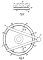
- a granulator for granulating slag which is a by-product from a blast furnace consists of a rotary atomiser having a duct along which molten slag is passed and poured on to the atomiser, an annular trough surrounding the atomiser and an enclosure in which the atomiser and the trough are located.
- the rotary atomiser (1) comprises a stationary electric motor driven by, for example, a variable speed drive and having a vertical drive shaft.
- a flange (3) supporting a refractory dish or cup (4).
- the dish or cup has an upwardly facing concave surface and it is rotated about a vertical axis. The speed of rotation of the dish or cup can be varied.
- the atomiser is located within a generally cylindrical enclosure (6) and a feed duct (7) extends from outside the enclosure to a position above the atomiser (1).
- An outlet nozzle (8) permits molten slag flowing down the duct (7) to fall as a stream on to the concave surface of the cup (4).
- the atomiser (1) Surrounding the atomiser (1) there is an annular trough (10) and the top of the trough is at a lower level than the cup (4).
- a frusto-conical surface (11) extends downwardly from the rotary atomiser to the adjacent top edge of the trough.
- the part (6A) of the side wall which is at a higher level than the top of the trough, has its lower end leading to the top of the trough.
- the enclosure is covered by a top structure (12) through which extends at least one discharge pipe (14).
- the part (6A) of the side wall of the enclosure may have a water jacket mounted on the outside thereof with provision for cooling liquid to be circulated through the jacket in order to cool the wall.
- this part of the side wall has downwardly directed openings (15) therethrough and a hollow casing behind the wall enables a cooling gas, usually air, to be directed through the openings into the enclosure.
- the flow of air is downwardly towards the trough (10).
- the frusto-conical surface (11) has openings therethrough and a casing below the surface enables gas, usually air, to be directed through the openings to the upper side of the surface. The direction of the air flow through the openings is towards the trough (10).
- the base of the trough (10) comprises a wind box (20) which is supplied with air under pressure from a source (not shown).
- the air is expelled through slots (21) formed in the top of the box.
- the slots (21) are inclined at an angle of up to 25° to direct the air expelled from the air box in a single circumferential direction around the trough.
- each conduit (22') or each duct (22") is positioned above one or other of a pair of conveyor belts or drag link conveyors (25) either directly or via inclined chutes (26).
- the conveyors may converge towards a single collection station (27).
- molten slag is allowed to flow down the duct (7) and fall as a stream on to the cup (4) of the atomiser (1) which is rotating at a speed usually between 750 rpm and 1200 rpm depending on slag flow rate. (Though speeds above this range are possible if required).
- the slag is ejected outwardly from the rotating cup (4) in the form of globules which spread out into the enclosure and heat transfer takes place between each globule and air within the enclosure to at least solidify the outer skin of the globule so that it becomes a granule.
- the granules will leave the trough through the exit but those that fail to leave through the exit will be moved on by the air flow from the wind box to the next exit where an opportunity to exit from the trough occurs.
- the granules leaving the exits are deposited on the conveyors (25) and taken to the collection point (27). It is to be emphasised that the trough (10) contains a circumferentially mobile bed. The granules are moved around the trough by the air flow in the trough but, though relatively high air velocities are required to do this, air velocities in the bed are low, avoiding significant elutriation of smaller particles and maintaining a relatively dense bed.
- the hot air generated in the enclosure passes out of the enclosure through the or each discharge pipe (14) and it can be used to advantage elsewhere in the plant.
- at least one system comprising a pipe (32) having a plurality of nozzles (33) connected to it is supported within the enclosure, conveniently adjacent to the cup (4). Water is circulated through the pipe to issue through the nozzles in the form of a very fine mist.
- air operated atomisers may be employed to produce the mist.
- the mist injected into the enclosure is evaporated by the heat present in the enclosure and the mist does not wet any of the surfaces inside the enclosure, but the evaporation of the water does reduce the air temperature within the enclosure.
- control circuit (not shown) which detects the temperature of the air within the enclosure and compares it with a predetermined value. When the temperature of the air reaches the predetermined value, the mist is generated in the enclosure in order to reduce the temperature. In this way, the temperature should be reduced below the predetermined value.
Landscapes
- Chemical & Material Sciences (AREA)
- Engineering & Computer Science (AREA)
- Organic Chemistry (AREA)
- Manufacturing & Machinery (AREA)
- Materials Engineering (AREA)
- Metallurgy (AREA)
- Chemical Kinetics & Catalysis (AREA)
- Furnace Details (AREA)
- Glanulating (AREA)
- Manufacture Of Iron (AREA)
- Curing Cements, Concrete, And Artificial Stone (AREA)
- Medicines Containing Plant Substances (AREA)
- Cosmetics (AREA)
- Processing Of Solid Wastes (AREA)
- Silver Salt Photography Or Processing Solution Therefor (AREA)
- Dry Development In Electrophotography (AREA)
Claims (15)
- Granulator, umfassend ein Gehäuse (6); einen in dem Gehäuse angeordneten Rotationszerstäuber (1); Mittel (7) zum Zuführen von Schmelzgut zum Zerstäuber, so daß während des Betriebes das Gut ohne die Anwendung von Fluldstrahlen in Kügelchen zerkleinert wird und die Kügelchen in dem Gehäuse verteilt werden; und eine den Zerstäuber umgebende, ringförmige, offene Rinne (10) zum Sammeln des aus den mindestens teilweise erstarrten Kügelchen gebildeten Granulates und Mittel zum Bewegen des Granulates in der Rinne zu mindestens einem Auslaß (22'; 22") aus der Rinne; dadurch gekennzeichnet, daß
die Rinne (10) in ihrem Boden Öffnungen (21) besitzt und Mittel (20) zum Injizieren von Gas durch die Öffnungen in die Rinne vorgesehen sind, wobei die Öffnungen so ausgerichtet sind, daß in der Rinne ein Gasstrom in Umfangsrichtung errichtet wird, der dazu dient, das Granulat in der Rinne zu dem mindestens einen Auslaß (22'; 22") zu bewegen. - Granulator gemäß Anspruch 1, dadurch gekennzeichnet, daß der oder jeder Auslaß aus der Rinne durch ein sich durch den Boden der Rinne erstreckendes Rohr (22') vorgesehen wird.
- Granulator gemäß Anspruch 1 oder 2, dadurch gekennzeichnet, daß der Rotationszerstäuber ein um eine vertikale Achse drehbares, feuerfestes Element (4) und das Mittel zum Zuführen von schmelzflüssigem Metall ein sich von der Außenseite des Gehäuses zu einer Stelle über dem feuerfesten Element (4) erstreckendes Zuführungsrohr (7) umfaßt, aus dem schmelzflüssiges Metall auf das feuerfeste Element fallen kann.
- Granulator gemäß Anspruch 1, 2 oder 3, bei dem die Seitenwand des Gehäuses einen Teil (6A) umfaßt, der sich auf einem höheren Niveau als das Oberteil der Rinne (10) befindet, wobei der Teil eine Ringform hat, deren unteres Ende zu dem Oberteil der Rinne führt.
- Granulator gemäß Anspruch 4, bei dem der Teil der Seitenwand flüssigkeitsgekühlt wird.
- Granulator gemäß Anspruch 4, bei dem der Teil (6A) der Seitenwand nach unten gerichtete Öffnungen (15) besitzt und Mittel zum Leiten von Kühlgas durch die Öffnungen in das Gehäuse vorgesehen sind.
- Granulator gemäß einem der vorhergehenden Ansprüche, bei dem sich eine geneigte Fläche (11) von dem Rotationszerstäuber nach unten zu der benachbarten Oberkante der Rinne erstreckt.
- Granulator gemäß Anspruch 7, bei dem die Fläche (11) Öffnungen darin besitzt und Mittel zum Leiten von Gas durch die Öffnungen zu der Oberseite der Fläche vorgesehen sind, wodurch das Gas während des Betriebes dazu dient, das auf der Fläche abgelagerte Granulat zu der ringförmigen Rinne zu leiten.
- Granulator gemäß einem der vorhergehenden Ansprüche, umfassend Mittel (32, 33) zum Einführen eines Wassernebels in das Gehäuse, um durch Verdunstung Wärme aus diesem zu abzuleiten.
- Granulator gemäß Anspruch 9, bei dem die Mittel zum Einführen des Wassernebels Wassersprühmittel oder luftbetriebene Wasserzerstäuber umfassen.
- Verfahren zum Granulieren eines Schmelzgutes, bei dem ein Strom aus dem Schmelzgut einem in einem Gehäuse angeordneten Rotationszerstäuber zugeführt wird; die Drehzahl des Zerstäubers so ist, daß das Schmelzgut von dem Zerstäuber ohne die Anwendung von Fluidstrahlen in der Form von Kügelchen abgegeben wird; der Durchgang der Kügelchen durch das Gehäuse das mindestens teilweise Erstarren derselben bewirkt, um Granulat zu bilden; das Granulat in einer den Zerstäuber umgebenden, ringförmigen, offenen Rinne gesammelt wird; gekennzeichnet dadurch, daß durch Öffnungen (21) in dem Boden der Rinne (10) eintretendes Gas in die Rinne (10) injiziert wird, um in der Rinne (10) eine Bewegung des Granulates in Umfangsrichtung zu mindestens einem Auslaß (22', 22") aus der Rinne (10) zu erzeugen.
- Verfahren gemäß Anspruch 11, bei dem eine Menge von zuvor gebildetem, gekühltem Granulat in der Rinne anwesend ist, um den Wärmeübergang von in der Rinne gesammeltem, heißen Granulat zu unterstützen.
- Verfahren gemäß Anspruch 11 oder 12, bei dem der Strom des Schmelzgutes auf ein feuerfestes Element des Rotationszerstäubers gegossen wird, wobei das Element um eine vertikale Achse gedreht wird.
- Verfahren gemäß Anspruch 11, 12 oder 13, bei dem die Betriebstemperatur in dem Gehäuse durch Einführen von Wassernebel in das Gehäuse geregelt wird, um durch Verdunstung des Wassernebels Wärme daraus abzuführen.
- Verfahren nach einem der Ansprüche 11 bis 14, bei dem das Schmelzgut Schlacke ist.
Applications Claiming Priority (3)
| Application Number | Priority Date | Filing Date | Title |
|---|---|---|---|
| GB919119788A GB9119788D0 (en) | 1991-09-17 | 1991-09-17 | Slag granulation |
| GB9119788 | 1991-09-17 | ||
| PCT/GB1992/001635 WO1993006250A1 (en) | 1991-09-17 | 1992-09-08 | Slag granulation |
Publications (2)
| Publication Number | Publication Date |
|---|---|
| EP0605472A1 EP0605472A1 (de) | 1994-07-13 |
| EP0605472B1 true EP0605472B1 (de) | 1997-04-02 |
Family
ID=10701492
Family Applications (1)
| Application Number | Title | Priority Date | Filing Date |
|---|---|---|---|
| EP92919028A Expired - Lifetime EP0605472B1 (de) | 1991-09-17 | 1992-09-08 | Granulieren von schlacke |
Country Status (14)
| Country | Link |
|---|---|
| US (1) | US5409521A (de) |
| EP (1) | EP0605472B1 (de) |
| JP (1) | JPH06510820A (de) |
| KR (1) | KR100256864B1 (de) |
| AT (1) | ATE151116T1 (de) |
| AU (1) | AU653859B2 (de) |
| CA (1) | CA2116328C (de) |
| DE (1) | DE69218784T2 (de) |
| ES (1) | ES2101868T3 (de) |
| GB (1) | GB9119788D0 (de) |
| IN (1) | IN186482B (de) |
| TW (1) | TW206933B (de) |
| WO (1) | WO1993006250A1 (de) |
| ZA (1) | ZA927112B (de) |
Families Citing this family (10)
| Publication number | Priority date | Publication date | Assignee | Title |
|---|---|---|---|---|
| GB9316767D0 (en) * | 1993-08-12 | 1993-09-29 | Davy Mckee Stockton | Slag granulation |
| US5882372A (en) * | 1994-10-26 | 1999-03-16 | Johns Manville International, Inc. | Apparatus for use in confining a gaseous stream containing wet or sticky particles or fibers |
| US6000242A (en) * | 1996-05-31 | 1999-12-14 | Kennecott Holdings Corporation | Apparatus for and process of water granulating matte or slag |
| KR100656769B1 (ko) * | 2006-06-28 | 2006-12-14 | (주)피엔알시스템 | 교량의 상부 구조물 내진성 강화 전단키 구조 |
| CA2729216C (en) * | 2008-06-27 | 2016-09-27 | Dongsheng Xie | Granulation of molten material |
| GB2493968B (en) | 2011-08-26 | 2013-12-18 | Siemens Plc | Slag granulation device & method |
| GB2493969B (en) | 2011-08-26 | 2013-08-07 | Siemens Plc | Slag dispersal device and method |
| GB2505672B (en) * | 2012-09-06 | 2014-09-17 | Siemens Plc | Dry slag granulation system |
| CN105624348B (zh) * | 2016-03-11 | 2018-03-02 | 西安交通大学 | 一种用于高温液态熔渣粒化系统 |
| CN114807463B (zh) * | 2022-05-26 | 2022-09-30 | 河北用邦环保设备科技有限公司 | 熔渣急冷粒化设备 |
Family Cites Families (6)
| Publication number | Priority date | Publication date | Assignee | Title |
|---|---|---|---|---|
| US3721511A (en) * | 1971-02-18 | 1973-03-20 | M Schlienger | Rotating arc furnace crucible |
| SU593817A1 (ru) * | 1975-12-04 | 1978-02-25 | Калушское производственное объединение "Хлорвинил" | Установка дл получени металлических гранул |
| US4256677A (en) * | 1976-04-12 | 1981-03-17 | Magnavox Government And Industrial Electronics Co. | Apparatus and method for making small spheres |
| US4373883A (en) * | 1979-01-09 | 1983-02-15 | Ishikawajima-Harima Jukogyo Kabushiki Kaisha | Apparatus for producing granules from molten metallurgical slags |
| DE3807720A1 (de) * | 1988-03-09 | 1989-09-21 | Norddeutsche Affinerie | Verfahren und vorrichtung zum granulieren fluessiger schlacken |
| US5259861A (en) * | 1992-03-05 | 1993-11-09 | National Science Council | Method for producing rapidly-solidified flake-like metal powder |
-
1991
- 1991-09-17 GB GB919119788A patent/GB9119788D0/en active Pending
-
1992
- 1992-09-08 US US08/199,309 patent/US5409521A/en not_active Expired - Fee Related
- 1992-09-08 JP JP5505863A patent/JPH06510820A/ja active Pending
- 1992-09-08 ES ES92919028T patent/ES2101868T3/es not_active Expired - Lifetime
- 1992-09-08 EP EP92919028A patent/EP0605472B1/de not_active Expired - Lifetime
- 1992-09-08 DE DE69218784T patent/DE69218784T2/de not_active Expired - Fee Related
- 1992-09-08 AT AT92919028T patent/ATE151116T1/de active
- 1992-09-08 WO PCT/GB1992/001635 patent/WO1993006250A1/en active IP Right Grant
- 1992-09-08 AU AU25071/92A patent/AU653859B2/en not_active Ceased
- 1992-09-08 KR KR1019940700861A patent/KR100256864B1/ko not_active IP Right Cessation
- 1992-09-08 CA CA002116328A patent/CA2116328C/en not_active Expired - Fee Related
- 1992-09-14 IN IN818DE1992 patent/IN186482B/en unknown
- 1992-09-16 TW TW081107300A patent/TW206933B/zh active
- 1992-09-17 ZA ZA927112A patent/ZA927112B/xx unknown
Also Published As
| Publication number | Publication date |
|---|---|
| AU2507192A (en) | 1993-04-27 |
| ES2101868T3 (es) | 1997-07-16 |
| WO1993006250A1 (en) | 1993-04-01 |
| AU653859B2 (en) | 1994-10-13 |
| GB9119788D0 (en) | 1991-10-30 |
| TW206933B (de) | 1993-06-01 |
| CA2116328C (en) | 1999-11-16 |
| DE69218784D1 (de) | 1997-05-07 |
| EP0605472A1 (de) | 1994-07-13 |
| CA2116328A1 (en) | 1993-04-01 |
| KR940702556A (ko) | 1994-08-20 |
| ATE151116T1 (de) | 1997-04-15 |
| DE69218784T2 (de) | 1997-07-10 |
| US5409521A (en) | 1995-04-25 |
| ZA927112B (en) | 1993-04-22 |
| JPH06510820A (ja) | 1994-12-01 |
| KR100256864B1 (ko) | 2000-05-15 |
| IN186482B (de) | 2001-09-15 |
Similar Documents
| Publication | Publication Date | Title |
|---|---|---|
| EP0804620B1 (de) | Granulieren von schlacke | |
| EP2300139B1 (de) | Verfahren zur atomisierung von flüssiger schlacke | |
| EP0605472B1 (de) | Granulieren von schlacke | |
| KR101695171B1 (ko) | 슬래그 과립화 시스템 및 작동 방법 | |
| JP5897064B2 (ja) | 溶融材料の造粒機 | |
| GB2148330A (en) | Improvements in or relating to the granulation of slag | |
| US5435945A (en) | Method and apparatus for generating sulphur seed particles for sulphur granule production | |
| US3054139A (en) | Method and apparatus for pelleting molten slag | |
| US4373883A (en) | Apparatus for producing granules from molten metallurgical slags | |
| SE412712B (sv) | Forfarande och anleggning for framstellning av pulver genom granulering av smelta | |
| CN110090595B (zh) | 一种斜面冷却造粒系统 | |
| JPH02102151A (ja) | 粒状スラグの製造装置 | |
| RU2388709C1 (ru) | Установка для переработки шлакового расплава и способ переработки шлакового расплава в этой установке | |
| SU1284699A1 (ru) | Установка дл получени дроби | |
| SU725804A1 (ru) | Устройство дл центробежной гранул ции расплава | |
| JPS5919531A (ja) | 溶融物の粒化方法 | |
| JPS5855094B2 (ja) | 粒滓の冷却回収方法及び装置 |
Legal Events
| Date | Code | Title | Description |
|---|---|---|---|
| PUAI | Public reference made under article 153(3) epc to a published international application that has entered the european phase |
Free format text: ORIGINAL CODE: 0009012 |
|
| 17P | Request for examination filed |
Effective date: 19940218 |
|
| AK | Designated contracting states |
Kind code of ref document: A1 Designated state(s): AT BE DE ES FR GB IT LU NL SE |
|
| 17Q | First examination report despatched |
Effective date: 19950419 |
|
| GRAG | Despatch of communication of intention to grant |
Free format text: ORIGINAL CODE: EPIDOS AGRA |
|
| GRAH | Despatch of communication of intention to grant a patent |
Free format text: ORIGINAL CODE: EPIDOS IGRA |
|
| GRAH | Despatch of communication of intention to grant a patent |
Free format text: ORIGINAL CODE: EPIDOS IGRA |
|
| GRAA | (expected) grant |
Free format text: ORIGINAL CODE: 0009210 |
|
| AK | Designated contracting states |
Kind code of ref document: B1 Designated state(s): AT BE DE ES FR GB IT LU NL SE |
|
| REF | Corresponds to: |
Ref document number: 151116 Country of ref document: AT Date of ref document: 19970415 Kind code of ref document: T |
|
| ET | Fr: translation filed | ||
| REF | Corresponds to: |
Ref document number: 69218784 Country of ref document: DE Date of ref document: 19970507 |
|
| REG | Reference to a national code |
Ref country code: ES Ref legal event code: FG2A Ref document number: 2101868 Country of ref document: ES Kind code of ref document: T3 |
|
| PG25 | Lapsed in a contracting state [announced via postgrant information from national office to epo] |
Ref country code: SE Free format text: LAPSE BECAUSE OF NON-PAYMENT OF DUE FEES Effective date: 19970909 Ref country code: ES Free format text: LAPSE BECAUSE OF NON-PAYMENT OF DUE FEES Effective date: 19970909 |
|
| PLBE | No opposition filed within time limit |
Free format text: ORIGINAL CODE: 0009261 |
|
| STAA | Information on the status of an ep patent application or granted ep patent |
Free format text: STATUS: NO OPPOSITION FILED WITHIN TIME LIMIT |
|
| 26N | No opposition filed | ||
| EUG | Se: european patent has lapsed |
Ref document number: 92919028.8 |
|
| PGFP | Annual fee paid to national office [announced via postgrant information from national office to epo] |
Ref country code: GB Payment date: 20010822 Year of fee payment: 10 |
|
| PGFP | Annual fee paid to national office [announced via postgrant information from national office to epo] |
Ref country code: FR Payment date: 20010830 Year of fee payment: 10 |
|
| PGFP | Annual fee paid to national office [announced via postgrant information from national office to epo] |
Ref country code: LU Payment date: 20010905 Year of fee payment: 10 |
|
| PGFP | Annual fee paid to national office [announced via postgrant information from national office to epo] |
Ref country code: BE Payment date: 20010907 Year of fee payment: 10 |
|
| PGFP | Annual fee paid to national office [announced via postgrant information from national office to epo] |
Ref country code: DE Payment date: 20010928 Year of fee payment: 10 |
|
| REG | Reference to a national code |
Ref country code: GB Ref legal event code: IF02 |
|
| PG25 | Lapsed in a contracting state [announced via postgrant information from national office to epo] |
Ref country code: LU Free format text: LAPSE BECAUSE OF NON-PAYMENT OF DUE FEES Effective date: 20020908 Ref country code: GB Free format text: LAPSE BECAUSE OF NON-PAYMENT OF DUE FEES Effective date: 20020908 |
|
| PG25 | Lapsed in a contracting state [announced via postgrant information from national office to epo] |
Ref country code: BE Free format text: LAPSE BECAUSE OF NON-PAYMENT OF DUE FEES Effective date: 20020930 |
|
| BERE | Be: lapsed |
Owner name: *DAVY MCKEE (STOCKTON) LTD Effective date: 20020930 |
|
| PG25 | Lapsed in a contracting state [announced via postgrant information from national office to epo] |
Ref country code: DE Free format text: LAPSE BECAUSE OF NON-PAYMENT OF DUE FEES Effective date: 20030401 |
|
| GBPC | Gb: european patent ceased through non-payment of renewal fee |
Effective date: 20020908 |
|
| PG25 | Lapsed in a contracting state [announced via postgrant information from national office to epo] |
Ref country code: FR Free format text: LAPSE BECAUSE OF NON-PAYMENT OF DUE FEES Effective date: 20030603 |
|
| REG | Reference to a national code |
Ref country code: FR Ref legal event code: ST |
|
| REG | Reference to a national code |
Ref country code: ES Ref legal event code: FD2A Effective date: 19981013 |
|
| PG25 | Lapsed in a contracting state [announced via postgrant information from national office to epo] |
Ref country code: IT Free format text: LAPSE BECAUSE OF NON-PAYMENT OF DUE FEES;WARNING: LAPSES OF ITALIAN PATENTS WITH EFFECTIVE DATE BEFORE 2007 MAY HAVE OCCURRED AT ANY TIME BEFORE 2007. THE CORRECT EFFECTIVE DATE MAY BE DIFFERENT FROM THE ONE RECORDED. Effective date: 20050908 |
|
| PGFP | Annual fee paid to national office [announced via postgrant information from national office to epo] |
Ref country code: AT Payment date: 20110810 Year of fee payment: 20 |
|
| PGFP | Annual fee paid to national office [announced via postgrant information from national office to epo] |
Ref country code: NL Payment date: 20110913 Year of fee payment: 20 |
|
| REG | Reference to a national code |
Ref country code: NL Ref legal event code: TD Owner name: SIEMENS VAI METALS TECHNOLOGIES LTD, GB Free format text: FORMER OWNER: DAVY MCKEE (STOCKTON) LIMITED, GB Effective date: 20120427 Ref country code: NL Ref legal event code: TD Effective date: 20120507 Ref country code: NL Ref legal event code: SD Effective date: 20120507 |
|
| REG | Reference to a national code |
Ref country code: AT Ref legal event code: PC Ref document number: 151116 Country of ref document: AT Kind code of ref document: T Owner name: SIEMENS VAI METALS TECHNOLOGIES LTD., GB Effective date: 20120518 |
|
| REG | Reference to a national code |
Ref country code: NL Ref legal event code: V4 Effective date: 20120908 |
|
| REG | Reference to a national code |
Ref country code: AT Ref legal event code: MK07 Ref document number: 151116 Country of ref document: AT Kind code of ref document: T Effective date: 20120908 |