EP0604286B1 - Verbindungselement zwischen zwei Bauteilen - Google Patents
Verbindungselement zwischen zwei Bauteilen Download PDFInfo
- Publication number
- EP0604286B1 EP0604286B1 EP93403083A EP93403083A EP0604286B1 EP 0604286 B1 EP0604286 B1 EP 0604286B1 EP 93403083 A EP93403083 A EP 93403083A EP 93403083 A EP93403083 A EP 93403083A EP 0604286 B1 EP0604286 B1 EP 0604286B1
- Authority
- EP
- European Patent Office
- Prior art keywords
- zone
- arched
- width
- key
- arc
- Prior art date
- Legal status (The legal status is an assumption and is not a legal conclusion. Google has not performed a legal analysis and makes no representation as to the accuracy of the status listed.)
- Expired - Lifetime
Links
Images

Classifications
-
- F—MECHANICAL ENGINEERING; LIGHTING; HEATING; WEAPONS; BLASTING
- F16—ENGINEERING ELEMENTS AND UNITS; GENERAL MEASURES FOR PRODUCING AND MAINTAINING EFFECTIVE FUNCTIONING OF MACHINES OR INSTALLATIONS; THERMAL INSULATION IN GENERAL
- F16F—SPRINGS; SHOCK-ABSORBERS; MEANS FOR DAMPING VIBRATION
- F16F1/00—Springs
- F16F1/36—Springs made of rubber or other material having high internal friction, e.g. thermoplastic elastomers
- F16F1/373—Springs made of rubber or other material having high internal friction, e.g. thermoplastic elastomers characterised by having a particular shape
- F16F1/3732—Springs made of rubber or other material having high internal friction, e.g. thermoplastic elastomers characterised by having a particular shape having an annular or the like shape, e.g. grommet-type resilient mountings
-
- F—MECHANICAL ENGINEERING; LIGHTING; HEATING; WEAPONS; BLASTING
- F16—ENGINEERING ELEMENTS AND UNITS; GENERAL MEASURES FOR PRODUCING AND MAINTAINING EFFECTIVE FUNCTIONING OF MACHINES OR INSTALLATIONS; THERMAL INSULATION IN GENERAL
- F16F—SPRINGS; SHOCK-ABSORBERS; MEANS FOR DAMPING VIBRATION
- F16F7/00—Vibration-dampers; Shock-absorbers
-
- F—MECHANICAL ENGINEERING; LIGHTING; HEATING; WEAPONS; BLASTING
- F16—ENGINEERING ELEMENTS AND UNITS; GENERAL MEASURES FOR PRODUCING AND MAINTAINING EFFECTIVE FUNCTIONING OF MACHINES OR INSTALLATIONS; THERMAL INSULATION IN GENERAL
- F16F—SPRINGS; SHOCK-ABSORBERS; MEANS FOR DAMPING VIBRATION
- F16F2230/00—Purpose; Design features
- F16F2230/0047—Measuring, indicating
-
- Y—GENERAL TAGGING OF NEW TECHNOLOGICAL DEVELOPMENTS; GENERAL TAGGING OF CROSS-SECTIONAL TECHNOLOGIES SPANNING OVER SEVERAL SECTIONS OF THE IPC; TECHNICAL SUBJECTS COVERED BY FORMER USPC CROSS-REFERENCE ART COLLECTIONS [XRACs] AND DIGESTS
- Y10—TECHNICAL SUBJECTS COVERED BY FORMER USPC
- Y10T—TECHNICAL SUBJECTS COVERED BY FORMER US CLASSIFICATION
- Y10T403/00—Joints and connections
- Y10T403/45—Flexibly connected rigid members
- Y10T403/455—Elastomer interposed between radially spaced members
- Y10T403/456—Elastomer encompasses shoulder on inner member
-
- Y—GENERAL TAGGING OF NEW TECHNOLOGICAL DEVELOPMENTS; GENERAL TAGGING OF CROSS-SECTIONAL TECHNOLOGIES SPANNING OVER SEVERAL SECTIONS OF THE IPC; TECHNICAL SUBJECTS COVERED BY FORMER USPC CROSS-REFERENCE ART COLLECTIONS [XRACs] AND DIGESTS
- Y10—TECHNICAL SUBJECTS COVERED BY FORMER USPC
- Y10T—TECHNICAL SUBJECTS COVERED BY FORMER US CLASSIFICATION
- Y10T403/00—Joints and connections
- Y10T403/70—Interfitted members
- Y10T403/7005—Lugged member, rotary engagement
- Y10T403/7007—Bayonet joint
Definitions
- the present invention relates to a connection device between two mechanical sheet metal parts, said connection having to prevent, after its implementation, the two parts from pivoting with respect to each other about an axis perpendicular to their plane of junction, one of said parts comprising for this purpose at least one notch in an arc centered on said axis and having a first arcuate zone having radially a first width and a second arcuate zone having radially a second width, smaller than said first width, this second zone, considered according to a direction of rotation determined around said axis, following the first zone.
- the invention is intended more particularly to ensure the fixing of an elastic stud on the cradle of a motor vehicle, this cradle can carry for example the power train and the front axle, and several of these studs being intended to ensure a connection elastic between this cradle and the vehicle chassis.
- the rigid external frame of such a stud is fixed to the cradle by three or even four screw-nut systems, which is not economical, neither from the point of view of the material, nor from the point of view of the assembly time. Then, a bolt is introduced into an inner tubular frame of the stud, to ensure its attachment to the chassis of the vehicle.
- a double blocking that is to say not only a blocking preventing any relative rotation between the two parts, but also a blocking suitable for putting them and keeping them under pressure. one against the other according to a common junction plane, this to avoid between the two parts any game generating noise and wear.
- the known type devices mentioned above do not allow this second blocking characteristic.
- the object of the present invention is to fill this gap and also to obtain a connection device making it possible to make the fastening of the armature of such a stud on the cradle, or any other part of it much faster and more economical. vehicle and, more generally, the fixing one on the other of two sheet metal parts, when one wants to avoid the use of many systems of the screw-nut type.
- a connection device is characterized in that the said notch in a circular arc also has a third zone disposed between the first zone and the second zone, this third zone having a progressively decreasing width radially. in said determined direction of rotation, this width having as maximum value that of said first arcuate area, and as minimum value a width at most equal to that of said second arcuate area; in that the other of said parts comprises at least one elastic tab in flexion and suitable for engaging in said first arcuate zone of the aforementioned notch when the two parts are brought against each other, said tab having to this effect, in the radial direction, a width slightly less than that of said first arcuate zone, but greater than that of said second arcuate zone, so that the relative rotation of said other part around the aforementioned axis, in said direction of determined rotation, ensures the aforementioned double locking of the two said parts with respect to each other, and in that the said tab is obtained by cutting and bending the sheet of the said other part and is shaped so as
- said minimum value of the radial width of the third arcuate zone is less than that of the second arcuate zone, so as to constitute for said tab a blocking stop preventing it, when it has been introduced into said second arcuate zone , to pivot in the direction of rotation opposite to said determined direction of rotation, and thus to return to said first arcuate zone.
- one of the edges of the notch in an arc of a circle has the shape of an arc of a circle in said first area and the shape of an arc of a circle of radius different from the previous one in said second area , these two circular arcs being connected by a ramp constituting the corresponding edge of said third arcuate zone.
- a device according to the invention can also be characterized in that there are provided two notches in a circular arc preferably symmetrical to one another with respect to said axis, as well as two elastic tabs arranged one with respect to the other in the same relative position as said notches, so as to be able to engage each and respectively, simultaneously in the first arcuate zone of said notches during the implementation of said link.
- said sheet metal parts comprise a relative centering system disposed internally with respect to said notches and having on one of said parts a circular opening, and on the other part a collar with circular section, suitable for engaging in said opening during the implementation of said connection.
- said circular opening is formed in the part which comprises said notches in an arc, and said collar in the part which comprises said tabs, which is more convenient to manufacture, since all the parts to be stamped are then located on the same piece, the other piece being only cut out.
- the invention also relates to an elastic stud, in particular intended to ensure an elastic connection between a cradle and a vehicle chassis, of the type comprising a mass of elastic material adhered around a rigid passage tube as well as between a plate of frame and a sheet metal part, this sheet metal part being secured to said cradle by means of a connecting device in accordance with what has just been described, and the stud can then be fixed to said chassis by means of a single through bolt said tube and fixed to the frame by a clamping nut.
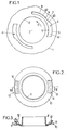
- the part of the sheet metal part which is shown in FIG. 1 is referenced at 1; it has a circular opening 2, the center of which is referenced 3.
- This part comprises, on either side of this opening 2, two arcuate notches 4 which, advantageously, are identical and symmetrical to each other with respect to the center 3. It is therefore necessary to describe only one, for example the one on the right in the drawing.
- the radially inner edge 5 of this notch is an arc of a circle concentric with the opening 2; its radially outer edge comprises, in the direction of rotation represented by arrow A, a circular arc 6, a straight ramp 7 and a circular arc 8, these two circular arcs being also concentric with the opening 2 but the circular arc 8 having a radius significantly less than that of the circular arc 6.
- the notch in a circular arc 4 has a first arcuate zone 41 whose radial width is greater than that of its second arcuate zone 42; as for the third arcuate zone 43, it is of progressively decreasing width according to the direction of rotation A; its maximum radial width is equal to the radial width of the zone 41, and its minimum radial width is less than the width of the zone 42, so as to constitute at its front end a radial blocking stop 9.
- the other part of the connection is referenced at 10 in FIGS. 2 and 3. It has a collar 11 of circular section, suitable for engaging in the opening 2 of the part 1.
- On either side of this collar 11 are cut from the sheet two elastic tabs 12 which are advantageously identical and diametrically opposite one another, in a relative position such that they can engage respectively and simultaneously in the arcuate areas 41 of the notches 4 of the part 1 when the connection between the two parts is implemented.
- the radial width W of these tabs seen in plan, is of course slightly less than the radial width of the arcuate zones 41, while remaining greater than the radial width of the arcuate zones 42.
- the tabs 12 After passing the blocking stops 9, the tabs 12 will return radially outwards by penetrating into the arcuate zones 42, their lower surface 13 coming to bear on the arc of a circle 8 and their corresponding edge 14 cooperating with the stop 9 to prevent any rotation in the opposite direction, around an axis passing through the center 3 and perpendicular to the junction plane of the two parts.
- the elastic tabs 12 it can also be noted that it is advantageous to conform them in such a way that the average height h of the space provided between their lower surface 13 and the upper plane of the flat part of the part 10 is slightly less than the thickness of the sheet which constitutes the part 1 (see Figure 3). In this way, after their assembly, the parts 1 and 10 will be slightly pressed against each other, due to the elasticity of the tabs 12, which will avoid any play that generates noise and wear, between these two parts. .
- a connecting device such as that which has just been described can advantageously be used to fix elastic cradles intended to ensure an elastic connection between this cradle and the chassis on the cradle of a motor vehicle; it could for example be a cradle on which the powertrain and the front axle of the vehicle are fixed.
- Such an elastic pad has been shown in the figure 4, and is designated by the reference 15.
- This stud comprises a mass of elastic material 16, for example an elastomer, adhered between an external reinforcing plate 17 and a piece 10 of sheet metal, which may be precisely that of FIGS. 2 and 3.
- the sheet constituting the cradle is cut in accordance with the representation of FIG. 1 and has been referenced in 1. It is therefore very easy and economical to fix such an elastic stud 15 on the cradle 1 of the vehicle, by proceeding as indicated more high to secure the part 10 on the part 1.
- this stud When this stud has been fixed on the sheet 1, it can be fixed on the chassis 18 of the vehicle in a conventional manner, by means of a single bolt 19, which passes through an axial passage tube rigid 20 of the pad 15, around which the elastic mass 16 is also adhered, this tube constituting an internal reinforcement of the pad.
- the tightening of the bolt 19 on the chassis 18 is ensured by a nut 21, and a washer 22 with a conical hole is interposed between the sheet metal 18 and the flared end 23 of the tube 20, this to prevent this end, which serves as a stop and which therefore receives the tightening force of the nut, does not deform the sheet 18 in the long run.
- FIG. 5 is a top view of the assembly thus produced, apart from the bolt 19, the nut 21, the sheet metal 18 and the washer 22.
- the invention thus makes it possible to avoid the usual use of three or four screw-nut assemblies to ensure the fixing of the stud 15 on the cradle 1.
- the connection device of the invention allows an extremely fast and economical fixing, while providing the same security as a conventional screw and nut system.
Landscapes
- Engineering & Computer Science (AREA)
- General Engineering & Computer Science (AREA)
- Mechanical Engineering (AREA)
- Connection Of Plates (AREA)
- Vehicle Body Suspensions (AREA)
- Motor Or Generator Frames (AREA)
Claims (7)
- Verbindungsvorrichtung zwischen zwei mechanischen Teilen (1, 10), wobei diese Teile aus Blech sind und die Verbindung nach deren Ausführung eine doppelte Sicherung gewährleisten muß, das heißt ein Pressen der zwei Teile (1, 10) gegeneinander entsprechend einer gemeinsamen Verbindungsebene, indem verhindert wird, daß sie sich einerseits an der gegenseitigen Andrückstelle voneinander entfernen, und andererseits das eine bezüglich des anderen um eine zu deren Verbindungsebene senkrechte Achse (3) schwenkt, bei welchem
(a) das eine (1) der Teile zumindest eine zu der Achse (3) zentrische, kreisbogenförmige Ausnehmung (4) hat, welche aufweist:- (aa) eine erste bogenförmige Zone (41), die radial eine erste Breite hat, und- (ab) eine zweite bogenförmige Zone (42), die radial eine zweite Breite hat, die kleiner als die erste Breite ist, wobei die zweite Zone bei Betrachtung einer festgelegten Drehrichtung (A) um die Achse auf die erste Zone folgt,dadurch gekennzeichnet, daß die Verbindungsvorrichtung- (ac) eine dritte Zone (43) aufweist, die zwischen der ersten und der zweiten Zone angeordnet ist, wobei die dritte Zone in radialer Richtung eine Breite hat, die in der festgelegten Drehrichtung (A) fortlaufend abnimmt, und diese Breite als maximalen Wert diejenige der ersten Zone (41) und als minimalen Wert eine Breite hat, die höchstens gleich derjenigen der zweiten bogenförmigen Zone (42) ist, und daß(b) das andere (10) der Teile zumindest einen biegeeleastischen Lappen (12) hat, der geeignet ist, in die erste bogenförmige Zone (41) der vorerwähnten Ausnehmung (4) einzugreifen, wenn die zwei Teile ineinander einzubringen sind, wobei der Lappen hierzu in radialer Richtung eine Breite hat, die etwas geringer ist als diejenige der ersten bogenförmigen Zone (41), aber größer als die in der zweiten bogenförmigen Zone (42) ist, so daß die relative Drehbewegung zu dem ersten Teil (10) um die vorerwähnte Achse (3) in der festgelegten Drehrichtung (A) die eingangs erwähnte doppelte Sicherung der beiden Teile gegeneinander gewährleistet, und daß der Lappen (12) durch Stanzen und Falzen des Blechs des anderen Teils (10) geschaffen und derart angepaßt ist, daß es sich bei dessen Drehbewegung um die festgelegte Drehachse (A) elastisch an einer Schräge (7) der dritten bogenförmigen Zone (43) abstützt, wobei die mittlere Höhe des Zwischenraums zwischen der unteren Fläche (13) des Lappens (12) und der oberen Fläche des das entsprechende Teil (10) bildenden Blechs ein wenig geringer als die Dicke des Blechs (1) ist, das die kreisbogenförmige Ausnehmung (4) aufweist. - Vorrichtung nach Anspruch 1, bei welchem der minimale Wert der radialen Breite der dritten bogenförmigen Zone (43) geringer ist als diejenige der zweiten bogenförmigen Zone (42), so daß für den Lappen (12) ein Sperranschlag (9) gebildet ist, der, wenn er in die zweite bogenförmige Zone (42) eingeführt worden ist, ein Verschwenken in der der festgelegten Drehrichtung (A) entgegengesetzten Drehrichtung, und auch ein Zurückkehren in die erste bogenförmige Zone (41) verhindert.
- Vorrichtung nach Anspruch 2, bei welchem einer der Ränder der kreisbogenförmigen Ausnehmung (4) die Form eines Kreisbogens (6) in der ersten Zone (41) und die Form eines Kreisbogens (8) mit einem zu dem vorhergehenden Kreisbogen (6) unterschiedlichen Radius in der zweiten Zone (42) aufweist, wobei diese beiden Kreisbogen durch die Schräge (7) verbunden sind, welche den Rand bildet, welcher der dritten bogenförmigen Zone (43) entspricht.
- Vorrichtung nach Anspruch 1, bei welchem zwei kreisbogenförmige Ausnehmungen (4) vorzugsweise symmetrisch bezüglich der Achse (3) und auch zwei elastische Lappen (12) vorgesehen sind, die zueinander in derselben relativen Position wie die Ausnehmungen angeordnet sind, so daß diese jeweils gleichzeitig in die erste bogenförmige Zone (41) der Ausnehmungen (4) bei der Ausführung des Verbindungsvorgangs eingreifen können.
- Vorrichtung nach Anspruch 4, bei welchem die Teile aus Blech ein relatives Zentriersystem haben, das im Inneren bezüglich der Ausnehmungen angeordnet ist und an einem der Teile eine kreisförmige Öffnung (2) und an dem anderen Teil einen Kragen (11) mit kreisförmigem Querschnitt aufweist, der geeignet ist, bei dem Ausführen des Verbindungsvorgangs in die Öffnung (2) einzugreifen.
- Vorrichtung nach Anspruch 5, bei welchem die kreisförmige Öffnung (2) in dem Teil (1), das die kreisbogenförmige Ausnehmung (4) aufweist, und der Kragen (11) an dem Teil (10) vorgesehen ist, das die Lappen (12) aufweist.
- Elastischer Block, der insbesondere dazu bestimmt ist, eine elastische Verbindung zwischen einem Aufbau (1) und einem Fahrzeugchassis (18) zu gewährleisten, enthaltend eine Verbindungsvorrichtung gemäß einem der vorhergehenden Ansprüche, eine Masse (16) aus elastischem Material, die um ein steifes Durchgangsrohr (20) herum sowie zwischen einer Abdeckplatte (17) und dem Blechteil (10) eingeklebt ist, wobei das Blechteil (10) an dem Aufbau (1) gesichert ist und der Block (15) auf dem Chassis (18) mittels einer einzigen, durch das Rohr (20) hindurchgehenden und an dem Chassis (18) mittels einer Feststellmutter (2) befestigten Bolzens (19) befestigt ist.
Applications Claiming Priority (2)
| Application Number | Priority Date | Filing Date | Title |
|---|---|---|---|
| US993836 | 1992-12-21 | ||
| US07/993,836 US5310276A (en) | 1992-12-21 | 1992-12-21 | Connection device between two mechanical components |
Publications (2)
| Publication Number | Publication Date |
|---|---|
| EP0604286A1 EP0604286A1 (de) | 1994-06-29 |
| EP0604286B1 true EP0604286B1 (de) | 1996-08-28 |
Family
ID=25539985
Family Applications (1)
| Application Number | Title | Priority Date | Filing Date |
|---|---|---|---|
| EP93403083A Expired - Lifetime EP0604286B1 (de) | 1992-12-21 | 1993-12-17 | Verbindungselement zwischen zwei Bauteilen |
Country Status (4)
| Country | Link |
|---|---|
| US (1) | US5310276A (de) |
| EP (1) | EP0604286B1 (de) |
| DE (1) | DE69304301T2 (de) |
| ES (1) | ES2090926T3 (de) |
Families Citing this family (25)
| Publication number | Priority date | Publication date | Assignee | Title |
|---|---|---|---|---|
| GB9122382D0 (en) * | 1991-10-22 | 1991-12-04 | Dunlop Ltd | Elastomeric mounting |
| US5409256A (en) * | 1994-01-04 | 1995-04-25 | General Motors Corporation | Driver-side air bag module assembly |
| US5507199A (en) * | 1994-01-18 | 1996-04-16 | Grand Haven Stamped Products | Shifter with locking cover |
| DE4406291B4 (de) * | 1994-02-26 | 2006-05-24 | Zf Sachs Ag | Übertragungsvorrichtung |
| US5641133A (en) * | 1994-05-11 | 1997-06-24 | Mcdonnell Douglas Helicopter Co. | Rotorcraft fuselage modal frequency placement using resilient mounting connections |
| DE19643407C2 (de) * | 1996-10-21 | 2000-08-10 | Ewald Witte Gmbh & Co Kg | Vorrichtung zum Halten zweier Bauteile in einer Abstandslage zueinander |
| JPH10238578A (ja) * | 1997-02-28 | 1998-09-08 | Toyo Tire & Rubber Co Ltd | 防振装置 |
| DE19723346A1 (de) * | 1997-06-04 | 1998-12-10 | Sram De Gmbh | Drehgriffschalter für Fahrradgetriebe |
| US6199801B1 (en) * | 1997-12-01 | 2001-03-13 | Csa Engineering, Inc. | Whole-spacecraft passive isolation devices |
| DE19758524C2 (de) * | 1997-12-11 | 2000-06-29 | Mannesmann Sachs Ag | Schwingungsdämpfer oder Federbein |
| FR2789464B1 (fr) * | 1999-02-05 | 2001-04-13 | Hutchinson | Support antivibratoire et son procede de fabrication |
| US6267347B1 (en) * | 1999-10-05 | 2001-07-31 | Peter Anthony Ryan | Acoustic mount |
| US6290183B1 (en) | 1999-10-19 | 2001-09-18 | Csa Engineering, Inc. | Three-axis, six degree-of-freedom, whole-spacecraft passive vibration isolation system |
| US6464214B1 (en) * | 2000-09-07 | 2002-10-15 | Paulstra Crc | Anti-vibration mounting for clip-fit connection means and vehicle fitted with this mounting |
| US20030218162A1 (en) * | 2002-05-23 | 2003-11-27 | Tackett James R. | Fence spool |
| DE102006060829B4 (de) * | 2006-12-22 | 2010-03-25 | Keiper Gmbh & Co. Kg | Lageranordnung, insbesondere eines Fahrzeugsitzes |
| US20080202846A1 (en) * | 2007-02-23 | 2008-08-28 | Mtec, Llc | Device and method for dampening sound transmission and vibration |
| AU2010201329B2 (en) * | 2009-04-03 | 2012-05-10 | Lg Electronics Inc. | Fabric treating machine |
| US8720922B2 (en) * | 2009-04-22 | 2014-05-13 | Transportation Technologies, Inc. | Suspension system with single moving element |
| DE102009047831A1 (de) * | 2009-09-30 | 2011-03-31 | Protektorwerk Florenz Maisch Gmbh & Co. Kg | Zusammenbauteil und Verfahren zum Herstellen eines Zusammenbauteils |
| US8622376B2 (en) * | 2010-01-19 | 2014-01-07 | Normand R. Lavigne | Vibration isolator |
| US20130045044A1 (en) * | 2010-04-28 | 2013-02-21 | Toyota Jidosha Kabushiki Kaisha | Case-fixing structure |
| US11118616B2 (en) | 2016-05-19 | 2021-09-14 | Christopher Prevost | Vibration isolator for turnlock fasteners |
| US10527084B2 (en) | 2016-05-19 | 2020-01-07 | Christopher Prevost | Elastomeric collar for fasteners |
| DE102018120105B4 (de) * | 2018-08-17 | 2023-02-16 | Nidec Gpm Gmbh | Dämpfungselement mit Bajonettverschluss |
Family Cites Families (7)
| Publication number | Priority date | Publication date | Assignee | Title |
|---|---|---|---|---|
| US3776649A (en) * | 1972-08-23 | 1973-12-04 | Barnes Eng Co | Locking ball joint |
| FR2527284A1 (fr) * | 1982-05-19 | 1983-11-25 | Neiman Sa | Dispositif de solidarisation en rotation |
| US4503292A (en) * | 1982-10-18 | 1985-03-05 | International Jensen Incorporated | Cammed latching system for loudspeaker and grille |
| GB2171447B (en) * | 1985-02-22 | 1989-08-31 | Automotive Products Plc | A disengageable coupling and a clutch release mechanism incorporating the same |
| US4632594A (en) * | 1985-06-24 | 1986-12-30 | Burroughs Corporation | Coupling apparatus |
| FR2603542B1 (fr) * | 1986-09-10 | 1988-11-10 | Bendix France | Ensemble d'un servomoteur de freinage monte sur une paroi fixe d'un vehicule et procede d'assemblage d'un tel ensemble |
| DE8715181U1 (de) * | 1987-10-17 | 1987-12-03 | Ledermann Gmbh + Co, 7240 Horb, De |
-
1992
- 1992-12-21 US US07/993,836 patent/US5310276A/en not_active Expired - Fee Related
-
1993
- 1993-12-17 ES ES93403083T patent/ES2090926T3/es not_active Expired - Lifetime
- 1993-12-17 DE DE69304301T patent/DE69304301T2/de not_active Expired - Fee Related
- 1993-12-17 EP EP93403083A patent/EP0604286B1/de not_active Expired - Lifetime
Also Published As
| Publication number | Publication date |
|---|---|
| DE69304301D1 (de) | 1996-10-02 |
| EP0604286A1 (de) | 1994-06-29 |
| DE69304301T2 (de) | 1997-02-13 |
| ES2090926T3 (es) | 1996-10-16 |
| US5310276A (en) | 1994-05-10 |
Similar Documents
| Publication | Publication Date | Title |
|---|---|---|
| EP0604286B1 (de) | Verbindungselement zwischen zwei Bauteilen | |
| EP0161149B1 (de) | Abdichtungsvorrichtung | |
| FR2820375A1 (fr) | Dispositif de fixation pour accoudoir amovible et dispositif d'assise comportant un tel dispositif de fixation | |
| EP1012483A1 (de) | Anordnung zum befestigen eines rohrförmigen elements auf einem teil der struktur einer kraftfahrzeugkarosserie | |
| FR2761308A1 (fr) | Siege pour vehicule automobile | |
| EP2371713A1 (de) | Achssystem zur Verbindung eines Pylons unter einer Tragfläche eines Luftfahrzeugs | |
| EP0366504B1 (de) | Aufbau eines an eine Fahrzeugwand angebauten Bremskraftverstärkers | |
| FR2768794A1 (fr) | Embrayage de verrouillage pour un appareil d'accouplement hydrocinetique, notamment de vehicule automobile | |
| EP0655381B1 (de) | Lenksäuleneinheit, insbesondere für ein Kraftfahrzeug | |
| FR2798099A1 (fr) | Siege de vehicule dote d'un mecanisme d'articulation | |
| EP3683150B1 (de) | Verbindungsvorrichtung, die zwischen mindestens zwei teilen schwenkbar ist, luftfahrzeug, das eine abdeckung umfasst, die mit dieser schwenkbaren verbindungsvorrichtung ausgestattet ist | |
| EP0660203B1 (de) | Uhrengehäuse | |
| EP0292358A1 (de) | Vorrichtung zum Verbinden eines Lenkrades mit der Lenksäule und ihre Verwendung bei der Befestigung eines Autolenkrades | |
| FR2556061A1 (fr) | Embrayage a friction, et procede de fabrication associe | |
| FR2639161A1 (fr) | Rotule de palier, notamment de moteur electrique | |
| FR3087418A1 (fr) | Systeme de fixation d'un siege | |
| FR2679302A1 (fr) | Ecrou elastique perfectionne. | |
| FR2523066A1 (fr) | Dispositif de changement de vitesse pour une bicyclette | |
| BE1000787A6 (fr) | Groupe de branchement d'une lampe de signalisation. | |
| FR2720845A1 (fr) | Vis de réglage. | |
| FR2772441A1 (fr) | Dispositif de fixation concu pour le maintien d'une piece | |
| FR2717437A1 (fr) | Ensemble de colonne de direction réglable en position notamment pour véhicule automobile. | |
| FR2775707A1 (fr) | Procede et dispositif de fixation a bague pour panneaux | |
| FR2671147A1 (fr) | Dispositif d'immobilisation de deux pieces assemblees par pression de l'une sur l'autre, en particulier pour vehicule automobile. | |
| FR2828246A1 (fr) | Assemblage mecanique sans contraintes |
Legal Events
| Date | Code | Title | Description |
|---|---|---|---|
| PUAI | Public reference made under article 153(3) epc to a published international application that has entered the european phase |
Free format text: ORIGINAL CODE: 0009012 |
|
| AK | Designated contracting states |
Kind code of ref document: A1 Designated state(s): DE ES FR |
|
| 17P | Request for examination filed |
Effective date: 19940622 |
|
| 17Q | First examination report despatched |
Effective date: 19950516 |
|
| GRAH | Despatch of communication of intention to grant a patent |
Free format text: ORIGINAL CODE: EPIDOS IGRA |
|
| GRAA | (expected) grant |
Free format text: ORIGINAL CODE: 0009210 |
|
| AK | Designated contracting states |
Kind code of ref document: B1 Designated state(s): DE ES FR |
|
| REF | Corresponds to: |
Ref document number: 69304301 Country of ref document: DE Date of ref document: 19961002 |
|
| REG | Reference to a national code |
Ref country code: ES Ref legal event code: FG2A Ref document number: 2090926 Country of ref document: ES Kind code of ref document: T3 |
|
| REG | Reference to a national code |
Ref country code: ES Ref legal event code: FG2A Ref document number: 2090926 Country of ref document: ES Kind code of ref document: T3 |
|
| PLBE | No opposition filed within time limit |
Free format text: ORIGINAL CODE: 0009261 |
|
| STAA | Information on the status of an ep patent application or granted ep patent |
Free format text: STATUS: NO OPPOSITION FILED WITHIN TIME LIMIT |
|
| 26N | No opposition filed | ||
| PGFP | Annual fee paid to national office [announced via postgrant information from national office to epo] |
Ref country code: DE Payment date: 20041206 Year of fee payment: 12 |
|
| PGFP | Annual fee paid to national office [announced via postgrant information from national office to epo] |
Ref country code: ES Payment date: 20041213 Year of fee payment: 12 |
|
| PGFP | Annual fee paid to national office [announced via postgrant information from national office to epo] |
Ref country code: FR Payment date: 20041223 Year of fee payment: 12 |
|
| PG25 | Lapsed in a contracting state [announced via postgrant information from national office to epo] |
Ref country code: ES Free format text: LAPSE BECAUSE OF NON-PAYMENT OF DUE FEES Effective date: 20051219 |
|
| PG25 | Lapsed in a contracting state [announced via postgrant information from national office to epo] |
Ref country code: DE Free format text: LAPSE BECAUSE OF NON-PAYMENT OF DUE FEES Effective date: 20060701 |
|
| PG25 | Lapsed in a contracting state [announced via postgrant information from national office to epo] |
Ref country code: FR Free format text: LAPSE BECAUSE OF NON-PAYMENT OF DUE FEES Effective date: 20060831 |
|
| REG | Reference to a national code |
Ref country code: FR Ref legal event code: ST Effective date: 20060831 |
|
| REG | Reference to a national code |
Ref country code: ES Ref legal event code: FD2A Effective date: 20051219 |