EP0603817B1 - Verfahren zum Verbinden von Lichtwellenleitern mit integriert optischen Bauelementen - Google Patents
Verfahren zum Verbinden von Lichtwellenleitern mit integriert optischen Bauelementen Download PDFInfo
- Publication number
- EP0603817B1 EP0603817B1 EP93120606A EP93120606A EP0603817B1 EP 0603817 B1 EP0603817 B1 EP 0603817B1 EP 93120606 A EP93120606 A EP 93120606A EP 93120606 A EP93120606 A EP 93120606A EP 0603817 B1 EP0603817 B1 EP 0603817B1
- Authority
- EP
- European Patent Office
- Prior art keywords
- optical
- connecting material
- integrated optical
- optical components
- curing
- Prior art date
- Legal status (The legal status is an assumption and is not a legal conclusion. Google has not performed a legal analysis and makes no representation as to the accuracy of the status listed.)
- Expired - Lifetime
Links
Images



Classifications
-
- G—PHYSICS
- G02—OPTICS
- G02B—OPTICAL ELEMENTS, SYSTEMS OR APPARATUS
- G02B6/00—Light guides; Structural details of arrangements comprising light guides and other optical elements, e.g. couplings
- G02B6/24—Coupling light guides
- G02B6/36—Mechanical coupling means
- G02B6/38—Mechanical coupling means having fibre to fibre mating means
- G02B6/3801—Permanent connections, i.e. wherein fibres are kept aligned by mechanical means
- G02B6/3803—Adjustment or alignment devices for alignment prior to splicing
-
- C—CHEMISTRY; METALLURGY
- C08—ORGANIC MACROMOLECULAR COMPOUNDS; THEIR PREPARATION OR CHEMICAL WORKING-UP; COMPOSITIONS BASED THEREON
- C08G—MACROMOLECULAR COMPOUNDS OBTAINED OTHERWISE THAN BY REACTIONS ONLY INVOLVING UNSATURATED CARBON-TO-CARBON BONDS
- C08G77/00—Macromolecular compounds obtained by reactions forming a linkage containing silicon with or without sulfur, nitrogen, oxygen or carbon in the main chain of the macromolecule
- C08G77/04—Polysiloxanes
- C08G77/22—Polysiloxanes containing silicon bound to organic groups containing atoms other than carbon, hydrogen and oxygen
- C08G77/28—Polysiloxanes containing silicon bound to organic groups containing atoms other than carbon, hydrogen and oxygen sulfur-containing groups
-
- G—PHYSICS
- G02—OPTICS
- G02B—OPTICAL ELEMENTS, SYSTEMS OR APPARATUS
- G02B6/00—Light guides; Structural details of arrangements comprising light guides and other optical elements, e.g. couplings
- G02B6/24—Coupling light guides
- G02B6/26—Optical coupling means
- G02B6/30—Optical coupling means for use between fibre and thin-film device
Definitions
- the invention relates to a method for coupling of optical fibers with integrated optical components with special polycondensates of silicon as connecting material.
- LWL optical fiber
- IOC integrated optical components
- the main disadvantage is the low thermal stability. As a rule, the glue points soften at temperatures greater than 80 ° C. this has the result is that the fiber is misaligned. This misalignment of the FO goes with an increased light attenuation hand in hand.
- Another disadvantage of the previously used organic polymer adhesive is the high water absorption and the associated crystal formation at temperatures down to approx. minus 40 ° C. Especially this one Ice crystal formation at low temperatures affects among other things also on the mechanical and optical Properties very disadvantageous. Bad for the Organic polymer adhesives previously used continue that an increase in light attenuation too at temperatures from -5 ° C to approx. + 10 ° C.
- EP-A-0450624 describes those containing organic groups Polycondensates based on hydrolytically condensed compounds of the Silicon and possibly other elements from the Group B, Al, P, Sn, Pb, the transition metals, the Lanthanides and actinides for use as Adhesive and its use for optical, optoelectric or electronic components.
- EP-A-0455090 describes the connection of Optical fibers with integrated optical Components using UV-curable adhesives.
- connection points are realized that have high temperature stability, a low water absorption and an associated have low ice crystal formation.
- the procedure should also be suitable, the most varied Connecting materials together.
- connection material for the coupling of fiber optic cables and IOCs are related to chemical and thermal Stability as well as on the optical properties made the highest demands by the previous Exopid adhesives can only be partially fulfilled. In particular, it is important that there is little volume loss and sufficient strength of the connection is achieved when gluing. Due to the different optoelectronic applications for connecting fiber optics with IOCs the most different Materials needed. These include in particular Silica glass, lithium niobate, silicon, InP, GaAS, glass or polymers. The connecting material must be able to do this very differently Materials to connect with the fiber, one at the same time good elasticity is required to Relieve stresses under thermal stress. The Connection material must continue to be chemically and thermally be stable (up to 150 ° C).
- the connecting material quickly at low Temperatures (less than 250 ° C) cures and has good processability.
- the optical Properties is important that the connecting material has a refractive index between where the coupling partner lies. It is also important that of for the transmission of optical signals relevant transparency range in the wavelength range from 700 nm to 1800 nm.
- connection class is particularly characterized by this from that the organic residue can be varied can, so that an appropriate polymer with desired Properties can be made. It has has now surprisingly shown that this Polycondensates also in relation to the optical ones Properties meet all requirements. It is particularly advantageous that the Property potential through combination with others Materials that can be produced using the sol-gel process (Silane, Al, Ti compounds, etc.) or with others expand copolymerizable organic compounds leaves without the optical Properties, especially the transmission in the interested in optical applications Area is affected.
- the method according to the invention is applicable to all previously known methods for fiber optic / IOC coupling applicable.
- the coupling can either be after Pick-and-place procedure, multi-chip procedure or according to the one-chip method (see FIGS. 1a to 1c) be performed.
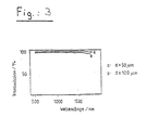
- the method according to the invention is related to all of these three common methods applicable. It is preferred if for gluing provided places with the connecting material be coated and only a very short curing with the help of suitable thermal or photo initiators he follows. It has been shown that it is sufficient if the curing time is maximum 1 min. is. Experiments have shown that excellent even with curing times of 20 s Results are achieved (see Fig. 3). As suitable Photoinitiators can be all commercially available be used.
- Examples include: Irgacure 184, Irgacure 500 and others from Ciba-Geigy Available photo initiators of the Irgacure type.
- the invention also includes all of these in the EP 0 450 624 photo initiators.
- thermal initiators can in particular organic peroxides in the form of diacyl peroxides or Peroxide carbonates are used. More thermal Initiators are also in EP 0 450 624 disclosed.
- the invention also includes all of these initiators with a. Basically, curing can either photochemically or on thermal Ways.
- the invention also relates to its use of the polyacrylate siloxane resins described above as a low loss loss connection material.
- the connecting material described above as a low loss loss connection material for the coupling of optical fibers used with integrated optical components can be. It has been shown that all required properties of this connecting material be excellently fulfilled.
- a connection is established using the pick-and-place procedure between an optical fiber and one integrated optical component manufactured (Fig. 1a).
- the curing is carried out by means of UV radiation made.
- the curing time is 20 s, the radiation power being 1.1 W UV-A and 0.35 W UV-B.
- Fig. 1 the three are in the form of a schematic diagram methods known from the prior art for FO / IOC coupling shown.
- Fig. 1a shows that Pick-and-place procedure.
- the connection material at the point 1 provided for the connection 2 applied.
- the optical fiber 3 is then inserted into the designated place.
- 4 provides a mounting plate and 5 shows the strip waveguide.
- Fig. 1b shows that Multi-chip process.
- the procedure is the same here, only that the optical fiber 3 in one Silicon substrate with V-grooves 6 is inserted.
- FIG. 1c one-chip method.
- the optical fiber 3 inserted into the strip waveguide 5 and the gluing in the designated place accomplished with the material according to the invention.
- the attenuation measurements were carried out using the cut-off method on multimode fibers.
- the corresponding device is shown in Fig. 2.
- two optical fibers 3 are connected via an adhesive point 7.
- the measurement is carried out with a transmitter 8, which is connected to a power supply 9, and a receiver 10, which is connected via a measuring device 11.
- the attenuation values for the connections made with the method according to the invention were ⁇ 0.3 dB per connection point.
- the measured damping values remain unchanged even after thermal cycling (Table 2).
- Thermal cycling test according to DIN IEC 68-2-14 cycle T min / ° C T max / ° C 5 stops / min Number of cycles I. -20 60 30th 2 II -40 80 30th 10 III -20 60 5 200
- IR spectroscopic measurements show layer thicknesses of 50 ⁇ m in the wavelength range 700 to 1800 nm 95% transmission and are therefore ideally suited for applications in the optoelectronic range.
- FIG. 4 shows the thermal behavior of the connecting materials used according to the invention. 4 shows the course of the differential thermal analysis (DTA), thermogravimetry (TG) and the differentiated thermogravimetry (DTG), which is typical for all connecting materials. It has been shown that there is no phase change of the systems. Furthermore, the exothermic reactions (DTA) correlate with the loss of mass due to the condensation of silanol groups and the associated elimination of H 2 O at 170 ° C and oxidative decomposition from 280 ° C.
- DTA differential thermal analysis
- TG thermogravimetry
- TMG differentiated thermogravimetry
- the thermal stability is thus at least 150 ° guaranteed, probably even over 200 ° C. This is compared to a significant improvement the conventional adhesives.
Landscapes
- Physics & Mathematics (AREA)
- Chemical & Material Sciences (AREA)
- General Physics & Mathematics (AREA)
- Optics & Photonics (AREA)
- Health & Medical Sciences (AREA)
- Chemical Kinetics & Catalysis (AREA)
- Medicinal Chemistry (AREA)
- Polymers & Plastics (AREA)
- Organic Chemistry (AREA)
- Mechanical Coupling Of Light Guides (AREA)
- Optical Couplings Of Light Guides (AREA)
Description

- Fig. 1
- zeigt die LWL/IOC-Koppelung nach folgendem
Verfahren:
- a) Pick-and-place-Verfahren,
- b) Mehrchip-Verfahren,
- c) Einchip-Verfahren.
- Fig. 2
- zeigt das Prinzip der Dämpfungsmessung nach der Abscheidemethode.
- Fig. 3
- zeigt die Transmission der Verbindungsmaterialien.
- Fig. 4
- zeigt das thermische Verhalten der Verbindungsmaterialien.
| Siloxansystem | E-Modul/MPa | n | Volumenschrumpf V0-V/V0/% |
| (1) mit X=0 | 20 | 1,56 | 2-3 |
| (1) mit X=CH3 | 10 | 1,56 | 2-3 |
| Temperaturwechselbelastungstest nach DIN IEC 68-2-14 | ||||
| Zyklus | Tmin/°C | Tmax/°C | 5Halt/min | Zyklenanzahl |
| I | -20 | 60 | 30 | 2 |
| II | -40 | 80 | 30 | 10 |
| III | -20 | 60 | 5 | 200 |
Claims (4)
- Verfahren zum Verbinden von Lichtwellenleitern (3) mit integriert optischen Bauelementen, wobei die zur Verklebung vorgesehenen Stellen (1) mit aushärtbarem Verbindungsmaterial (2) versehen werden, der Lichtwellenleiter ins Verbindungmaterial eingelegt und anschließend das Verbindungsmaterial (2) durch Bestrahlung und/oder thermische Energie ausgehärtet wird,
dadurch gekennzeichnet, daß
die zur Verklebung vorgesehenen Stellen (1) mit organische Gruppen enthaltenden Polykondensaten auf der Basis von hydrolytisch kondensierten Verbindungen des Siliciums und gegebenenfalls anderen Elementen aus der Gruppe B, Al, P, Sn, Pb, der Übergangsmetalle, der Lanthaniden und der Aktiniden als Verbindungsmaterial versehen werden, wobei das Polykondensat eine Verbindung der allgemeinen Formel (1) ist:in der X = O oder CH3 ist.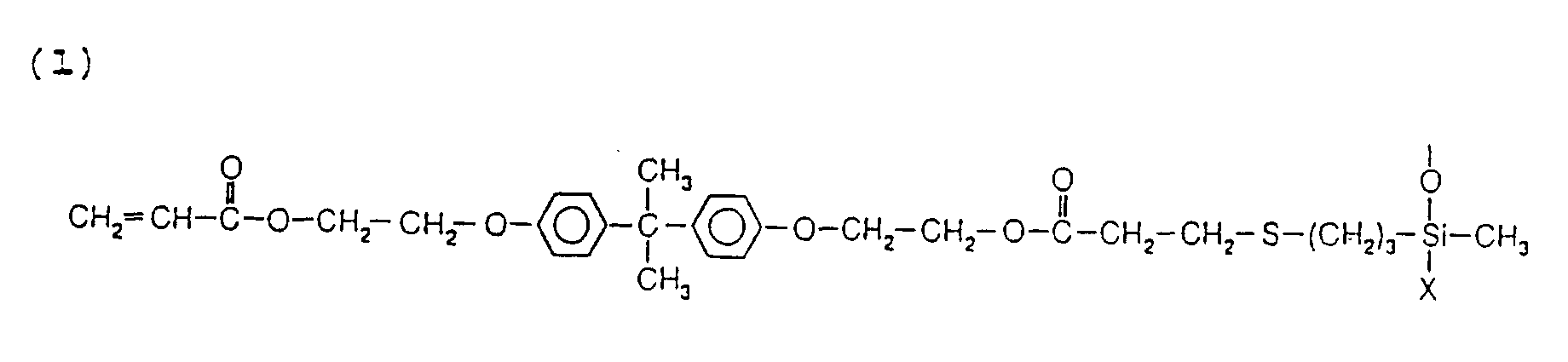
- Verfahren nach Anspruch 1,
dadurch gekennzeichnet, daß das Polykondensat ausgewählt wird in Abhängigkeit der geforderten mechanischen und optischen Eigenschaften, wie z.B. Elastizität, Brechungsindex oder Festigkeit in gehärtetem Material. - Verfahren nach einem der vorhergehenden Ansprüche,
dadurch gekennzeichnet, daß während des Aushärtevorganges durch Bestrahlung und/oder thermische Energie ein an sich bekannter geeigneter Fotoinitiator bzw. thermischer Initiator zugesetzt wird. - Verfahren nach einem der vorhergehenden Ansprüche,
dadurch gekennzeichnet, daß die Aushärtezeit maximal 1 min. ist.
Applications Claiming Priority (2)
| Application Number | Priority Date | Filing Date | Title |
|---|---|---|---|
| DE4243874 | 1992-12-23 | ||
| DE4243874A DE4243874C2 (de) | 1992-12-23 | 1992-12-23 | Optische Kopplungsvorrichtung |
Publications (2)
| Publication Number | Publication Date |
|---|---|
| EP0603817A1 EP0603817A1 (de) | 1994-06-29 |
| EP0603817B1 true EP0603817B1 (de) | 2001-09-12 |
Family
ID=6476418
Family Applications (1)
| Application Number | Title | Priority Date | Filing Date |
|---|---|---|---|
| EP93120606A Expired - Lifetime EP0603817B1 (de) | 1992-12-23 | 1993-12-21 | Verfahren zum Verbinden von Lichtwellenleitern mit integriert optischen Bauelementen |
Country Status (2)
| Country | Link |
|---|---|
| EP (1) | EP0603817B1 (de) |
| DE (2) | DE4243874C2 (de) |
Families Citing this family (1)
| Publication number | Priority date | Publication date | Assignee | Title |
|---|---|---|---|---|
| DE19964228B4 (de) * | 1998-09-08 | 2008-11-13 | Fujitsu Ltd., Kawasaki | Verfahren zur Herstellung eines Reflexionsfilms und Herstellung optischer Vorrichtungen die einen Reflexionsfilm verwenden |
Family Cites Families (3)
| Publication number | Priority date | Publication date | Assignee | Title |
|---|---|---|---|---|
| DE4011044A1 (de) * | 1990-04-05 | 1991-10-10 | Fraunhofer Ges Forschung | Silane, verfahren zu ihrer herstellung und ihre verwendung zur herstellung von polymerisaten und polykondensaten |
| FR2661516B1 (fr) * | 1990-04-27 | 1992-06-12 | Alcatel Fibres Optiques | Composant d'optique integree et procede de fabrication. |
| FR2674033B1 (fr) * | 1991-03-14 | 1993-07-23 | Corning Inc | Composant optique integre a liaison entre un guide d'onde integre et une fibre optique, fonctionnant dans un large domaine de temperature. |
-
1992
- 1992-12-23 DE DE4243874A patent/DE4243874C2/de not_active Expired - Fee Related
-
1993
- 1993-12-21 EP EP93120606A patent/EP0603817B1/de not_active Expired - Lifetime
- 1993-12-21 DE DE59310212T patent/DE59310212D1/de not_active Expired - Lifetime
Also Published As
| Publication number | Publication date |
|---|---|
| DE59310212D1 (de) | 2001-10-18 |
| DE4243874C2 (de) | 1997-09-18 |
| EP0603817A1 (de) | 1994-06-29 |
| DE4243874A1 (de) | 1994-06-30 |
Similar Documents
| Publication | Publication Date | Title |
|---|---|---|
| DE69205602T2 (de) | Faserbefestigungsmittel für eine integriert-optische Komponente. | |
| DE69428558T2 (de) | Kopplungsstruktur für optische Fasern und optische Wellenleiter | |
| DE69216840T2 (de) | Ummantelte optsiche fasern mit niedrigem verlust und mit einer hohen numerischen apertur | |
| DE69521567T2 (de) | Optisches Wellenleitermodul mit einem Substrat aus einem bestimmten Material und einem Ferrule aus einem anderen Material | |
| DE2512312C2 (de) | Verfahren zum Beschichten einer optischen Lichtleitglasfaser | |
| DE69430876T2 (de) | Optisches Faserarray und Methode zu seiner Herstellung | |
| DE69020958T2 (de) | Laser-Modul mit optischer Faser und Methode zu seiner Herstellung. | |
| DE69431459T2 (de) | Optisches Wellenleitermodul | |
| DE69421432T2 (de) | Optische Kollimatoren-Matrix und Verfahren zur Ausrichtung ihrer Achsen | |
| EP0212169A1 (de) | Füllmasse für Lichtwellenleiteradern und/oder Lichtwellenleiterkabel | |
| DE4310291A1 (de) | Optischer Koppler | |
| DE3021228A1 (de) | Verfahren zur anbringung einer optischen faser an einer halbleiteranordnung | |
| DE69015571T2 (de) | Strahlungshärtbare Beschichtungszusammensetzung. | |
| DE102018110001A1 (de) | Optische schaltung und verfahren zum herstellen derselben | |
| DE3524369A1 (de) | Optische faser mit polymethacrylat-kern und fluor-kopolymer-huelle | |
| DE2906104A1 (de) | Vorrichtung zum koppeln zweier lichtwellenleiter | |
| DE3605513C2 (de) | ||
| DE60019608T2 (de) | Verwendung eines lasers zum schmelzspleissen optischer komponenten mit unterschiedlischen querschnitten | |
| DE4243874C2 (de) | Optische Kopplungsvorrichtung | |
| DE102009023071A1 (de) | Mikrooptisches Koppelelement mit integrierten optischen Wellenleitern | |
| DE4445997C2 (de) | Anordnung zur Ankopplung einer Lichtleitfaser an ein optisches Bauelement | |
| EP0201028B1 (de) | Optischer Weichenbaustein | |
| DE10233974A1 (de) | Verbindungsteil für optische Fasern, Herstellungsverfahren dafür und optisches Bauteil | |
| DE60100144T2 (de) | Optische Wellenleitervorrichtung mit Fasergitter und Verfahren zu deren Herstellung | |
| WO2001061398A1 (de) | Optische lichwellenleiter-übertragungsstrecke mit passiver richtungsabhängiger dämpfung |
Legal Events
| Date | Code | Title | Description |
|---|---|---|---|
| PUAI | Public reference made under article 153(3) epc to a published international application that has entered the european phase |
Free format text: ORIGINAL CODE: 0009012 |
|
| AK | Designated contracting states |
Kind code of ref document: A1 Designated state(s): BE CH DE FR GB IT LI NL SE |
|
| 17P | Request for examination filed |
Effective date: 19940818 |
|
| 17Q | First examination report despatched |
Effective date: 19970120 |
|
| GRAG | Despatch of communication of intention to grant |
Free format text: ORIGINAL CODE: EPIDOS AGRA |
|
| GRAG | Despatch of communication of intention to grant |
Free format text: ORIGINAL CODE: EPIDOS AGRA |
|
| GRAH | Despatch of communication of intention to grant a patent |
Free format text: ORIGINAL CODE: EPIDOS IGRA |
|
| GRAH | Despatch of communication of intention to grant a patent |
Free format text: ORIGINAL CODE: EPIDOS IGRA |
|
| GRAA | (expected) grant |
Free format text: ORIGINAL CODE: 0009210 |
|
| AK | Designated contracting states |
Kind code of ref document: B1 Designated state(s): BE CH DE FR GB IT LI NL SE |
|
| PG25 | Lapsed in a contracting state [announced via postgrant information from national office to epo] |
Ref country code: IT Free format text: LAPSE BECAUSE OF FAILURE TO SUBMIT A TRANSLATION OF THE DESCRIPTION OR TO PAY THE FEE WITHIN THE PRE;WARNING: LAPSES OF ITALIAN PATENTS WITH EFFECTIVE DATE BEFORE 2007 MAY HAVE OCCURRED AT ANY TIME BEFORE 2007. THE CORRECT EFFECTIVE DATE MAY BE DIFFERENT FROM THE ONE RECORDED.SCRIBED TIME-LIMIT Effective date: 20010912 |
|
| REG | Reference to a national code |
Ref country code: CH Ref legal event code: EP |
|
| REF | Corresponds to: |
Ref document number: 59310212 Country of ref document: DE Date of ref document: 20011018 |
|
| ET | Fr: translation filed | ||
| PG25 | Lapsed in a contracting state [announced via postgrant information from national office to epo] |
Ref country code: LI Free format text: LAPSE BECAUSE OF NON-PAYMENT OF DUE FEES Effective date: 20011231 Ref country code: CH Free format text: LAPSE BECAUSE OF NON-PAYMENT OF DUE FEES Effective date: 20011231 Ref country code: BE Free format text: LAPSE BECAUSE OF NON-PAYMENT OF DUE FEES Effective date: 20011231 |
|
| REG | Reference to a national code |
Ref country code: GB Ref legal event code: IF02 |
|
| GBT | Gb: translation of ep patent filed (gb section 77(6)(a)/1977) |
Effective date: 20011201 |
|
| BERE | Be: lapsed |
Owner name: FRAUNHOFER-GESELLSCHAFT ZUR FORDERUNG DER ANGEWAN Effective date: 20011231 |
|
| PLBE | No opposition filed within time limit |
Free format text: ORIGINAL CODE: 0009261 |
|
| STAA | Information on the status of an ep patent application or granted ep patent |
Free format text: STATUS: NO OPPOSITION FILED WITHIN TIME LIMIT |
|
| REG | Reference to a national code |
Ref country code: CH Ref legal event code: PL |
|
| 26N | No opposition filed | ||
| PGFP | Annual fee paid to national office [announced via postgrant information from national office to epo] |
Ref country code: SE Payment date: 20091218 Year of fee payment: 17 |
|
| PGFP | Annual fee paid to national office [announced via postgrant information from national office to epo] |
Ref country code: NL Payment date: 20091221 Year of fee payment: 17 |
|
| PGFP | Annual fee paid to national office [announced via postgrant information from national office to epo] |
Ref country code: GB Payment date: 20091221 Year of fee payment: 17 Ref country code: FR Payment date: 20100105 Year of fee payment: 17 |
|
| PGFP | Annual fee paid to national office [announced via postgrant information from national office to epo] |
Ref country code: DE Payment date: 20100222 Year of fee payment: 17 |
|
| REG | Reference to a national code |
Ref country code: NL Ref legal event code: V1 Effective date: 20110701 |
|
| GBPC | Gb: european patent ceased through non-payment of renewal fee |
Effective date: 20101221 |
|
| REG | Reference to a national code |
Ref country code: FR Ref legal event code: ST Effective date: 20110831 |
|
| REG | Reference to a national code |
Ref country code: SE Ref legal event code: EUG |
|
| PG25 | Lapsed in a contracting state [announced via postgrant information from national office to epo] |
Ref country code: SE Free format text: LAPSE BECAUSE OF NON-PAYMENT OF DUE FEES Effective date: 20101222 |
|
| PG25 | Lapsed in a contracting state [announced via postgrant information from national office to epo] |
Ref country code: FR Free format text: LAPSE BECAUSE OF NON-PAYMENT OF DUE FEES Effective date: 20110103 |
|
| REG | Reference to a national code |
Ref country code: DE Ref legal event code: R119 Ref document number: 59310212 Country of ref document: DE Effective date: 20110701 |
|
| PG25 | Lapsed in a contracting state [announced via postgrant information from national office to epo] |
Ref country code: DE Free format text: LAPSE BECAUSE OF NON-PAYMENT OF DUE FEES Effective date: 20110701 Ref country code: GB Free format text: LAPSE BECAUSE OF NON-PAYMENT OF DUE FEES Effective date: 20101221 |
|
| PG25 | Lapsed in a contracting state [announced via postgrant information from national office to epo] |
Ref country code: NL Free format text: LAPSE BECAUSE OF NON-PAYMENT OF DUE FEES Effective date: 20110701 |