EP0603501B1 - Machine for manufacturing book covers - Google Patents
Machine for manufacturing book covers Download PDFInfo
- Publication number
- EP0603501B1 EP0603501B1 EP93117531A EP93117531A EP0603501B1 EP 0603501 B1 EP0603501 B1 EP 0603501B1 EP 93117531 A EP93117531 A EP 93117531A EP 93117531 A EP93117531 A EP 93117531A EP 0603501 B1 EP0603501 B1 EP 0603501B1
- Authority
- EP
- European Patent Office
- Prior art keywords
- cover
- turn
- boards
- plane
- book
- Prior art date
- Legal status (The legal status is an assumption and is not a legal conclusion. Google has not performed a legal analysis and makes no representation as to the accuracy of the status listed.)
- Expired - Lifetime
Links
Images

Classifications
-
- B—PERFORMING OPERATIONS; TRANSPORTING
- B42—BOOKBINDING; ALBUMS; FILES; SPECIAL PRINTED MATTER
- B42C—BOOKBINDING
- B42C7/00—Manufacturing bookbinding cases or covers of books or loose-leaf binders
-
- B—PERFORMING OPERATIONS; TRANSPORTING
- B32—LAYERED PRODUCTS
- B32B—LAYERED PRODUCTS, i.e. PRODUCTS BUILT-UP OF STRATA OF FLAT OR NON-FLAT, e.g. CELLULAR OR HONEYCOMB, FORM
- B32B38/00—Ancillary operations in connection with laminating processes
- B32B38/18—Handling of layers or the laminate
- B32B38/1825—Handling of layers or the laminate characterised by the control or constructional features of devices for tensioning, stretching or registration
Definitions
- the invention relates to a book cover machine according to the preamble of claim 1.
- book covers consist of a cover material, the two cover boards and a backing board, the so-called Schrenz, arranged between them.
- the cardboards are glued to the entire surface of the cover material and the cover material protruding from the cardboards is wrapped on all four sides.
- book cover machines take over the operations.
- the cut reference material the so-called blanket
- the cut reference material is separated from a stack magazine and fed to a glue roller via a cylinder.
- a screed takes over the glued ceiling benefit and places it on the ceiling table.
- transporters push the cut blankets out of magazines onto a staging area and at the same time a backing paper cut to length from the roll is fed.
- the two blankets of cardboard and the backing of cardboard are picked up by a suction head of a double suction arm and, after a rotation of the suction arm by 180 °, are brought together with the glued benefits lying on the ceiling table.
- the ceiling table and double suction arm move downwards with the ceiling panel and the cardboard in two stages, whereby in a first stage the projecting edges of the ceiling panel on the so-called head and foot side of the book cover are erected and folded in by a pair of fold-in strips and the corners are pulled in by tools carried along. In a second stage, the side folds were also erected and folded in using fold bars.
- a second suction head on the opposite side picks up new lidded cardboard from the magazines and then moves back to its upper starting position.
- the ceiling table finally makes a downward movement with the finished ceiling in a third stage, in which a means of transport grasps the ceiling and feeds it to a pressing device, and the ceiling table also moves back to its starting position for taking over a subsequent ceiling benefit.
- the object of the invention is to provide a book cover machine of the generic type, on which book covers of higher quality can be produced with a substantial increase in working speed while maintaining a compact design.
- the time saved for the individual movement sequences results overall in a smoother machine run and ultimately the book cover machine according to the invention has a compact design.
- the covering material 1a hereinafter referred to as a benefit
- a benefit is removed from a magazine 2 of a lay-up station by suction device 3 and fed to a blanket cylinder 4 which detects a benefit 1a with its grippers 4a at a standstill and on a glue roller 5 passes.
- a gripper bar 6 which can be moved forwards and backwards in a straight line takes over the glued panel 1a at a standstill from the panel cylinder 4 and places it on a table 7.
- a transport arm 14 which is rotatable about a vertical axis 13 and movable up and down in the vertical plane.
- the two blankets 1b are transported by transporters 17 into the preparation area 11, while the back insert 1c is fed from the roll and cut to length by means of a cutting unit 18.
- the transport arm 14 which can be moved between the preparation station 11 and the ceiling table 7 by rotary movement, picks up the provided cardboards 1b and 1c via the suction plate arrangement 15 and feeds them to the ceiling table 7, which is in a takeover position which runs obliquely to the cardboards 1b and 1c. After the rotary movement has ended, the transport arm 14 lowers and the cardboards 1b and 1c held by the suction plate arrangement 15 are first brought into contact with the panel 1a on the head-turning side.
- a wrapping station with wrapping elements arranged in vertically offset planes for executing the head and foot impacts in a first level and for carrying out the side wraps in a second level.
- the functions of joining the blanket 1 a and blankets 1b, head and foot wrap and side wrap are coordinated with one another in such a way that all functions take place simultaneously on different book covers, so that a machine cycle is available for every process including the transport movement.
- a transport device in the form of a suction bar 22 with suction pads 23 distributed thereon over the length of the blanket detects the blanket 1 assembled from the cardboards 1b, 1c and panels 1a on one side over its entire side length in order to feed it stretched to the wrapping station.
- the blanket 1 is underpinned on the side opposite the suction cups 23 by a support rail 24 which can be steered into the movement path and back.
- the suction bar 22 with the suction cups 23 is located on a carriage 25 with rollers 26 engaging on a guide track 27 and is moved back and forth by a drive system 28.
- suction rails 29 take over the ceiling 1 in the areas near the side in the feed plane.
- the suction rails 29 can be moved vertically via vertical guide rods 30 in the direction of the arrow and can thus press the ceiling 1 against pressure rails 31 after the support rail 24 has been moved back by a slight downward stroke.
- the pressure rails 31 can also remain below the impact rail 35 and the suction rails 29 take over the vertical transport.
- the downward movement takes place in a position in which the upper edge of the cover paper 1b and 1c is below the wrapping rails 35.
- the impact rails 35 move inward in the direction of the arrow, the suction rails 29 lift off and the pressure rails 31 press the ceiling to achieve a tight impact against the impact rails 35, which are still moving inwards.
- the corners are drawn in via corner retraction elements 33 which are guided by the impact rails 35.
- the pressure rails 31 detach from the ceiling and move outward in the direction of the arrow in order to clear the way for the ceiling 1 for a further downward movement into the side wrapping station located below.
- the ceiling 1 is taken over in the plane of the head and foot wrap by height-movable first sections 36a of suction strips arranged in parallel and distributed over the length of the ceiling, which initially move the ceiling 1 to an intermediate level, in which second height-adjustable sections 36b take over the ceiling 1. to lower them together with the first sections 36a to the level in which the side folds are carried out.
- the lateral projections of the ceiling 1 are erected on erection rails 37.
- the flipping of the side turns takes place in a known manner by driving in side turning rails 38 while exerting a contact pressure by the suction strips 36a, 36b.
- the suction strips 36a, 36b lower and place the blanket 1 on a transport system 39, 40 for the removal of the blanket 1 by transporters 39 of an export chain 40 into a downstream pressure roller pair 41 and on an adjoining export belt 42.
- cover cardboard 1b is placed on a cardboard pre-stacking belt 50 and automatically placed in a cardboard magazine 51, in which the front edge, formed by stops 52 with a passage strip function, is adjustable.
- the cardboard magazine 51 the cardboards 1b are separated by a short-stroke slide 53 and in front of transporters 54 placed on the side toothed belt 55.
- the slide 53 runs slightly obliquely downwards.
- the return stroke takes place immediately, which means that the stack is relieved.
- the engagement height of the transporters 54 is adjusted by height settings of guide rails, not shown.
- the toothed belts run continuously at cycle speed and transfer the cardboards 1b synchronously to a blanket cylinder 56 with an upper roller 57.
- the stops 52 are adjusted Extraction device coming to length and fed.
- the coverings 1a are fed, again referred to below as the benefit, namely by circumferential gripper bars 60 of a chain system 61 directly to the benefit cylinder 56.
- B. in the form of a scale from a pre-stacking belt 62 in a utility magazine 63, from which they are tipped down by a squeegee 64 and transferred to the gripper bar 60 by a synchronous movement of the squeegee 64 in the transport direction. Blown air can be used to loosen the pile of useful items in order to avoid rolling effects.
- the feed control of the panels 1a present in scale formation is carried out via light sensors 65.
- the book covers are kept at a height via support strips (not shown) so that upper suction devices 70 can take over the book cover while the chain system 69 is at a standstill.
- the suction devices 70 bring the book cover into the head and foot wrap plane and place it on the extended pressure rails 71.
- the head and foot impacts are erected on stationary erection rails 73.
- Wrapping rails 72 then perform the head and foot impact while the suction cups 70 return to their starting position upwards. With the head and foot impact, the corner is folded over known corner retraction elements.
- lower suction devices 74 move under the book covers, to take them over after the wrapping has ended and to transport them downward into the side wrap plane after the pressure rails 71 and wrapping rails 72 have been retracted.
- the book cover is placed on side suction rails 75, which are advanced at this time and hold the book cover with suction cups.
- the side impact is now effected via the impact rail 76, in that the impact is erected by a vertical movement and rubbed by a subsequent horizontal movement.
- the suckers 74 move out of the format area in the direction of the head and foot of the book cover, so that after the suction rails 75 and wrapping rails 76 have been pulled back, the book cover can fall onto the execution level.
- the lower suction cups 74 now run with an oblique movement upwards into the takeover position of the head and foot impact plane. In this case, deflectors on the suckers 74 inevitably accelerate the finished book cover downward, so that the transport to the execution level is not dependent on free fall.
- the book cover falls on a support table 78 and is pushed there by a conveyor chain 79 running constantly at cycle speed into the rolling station 80.
- the lower suction cups 74 perform a movement in the direction of the arrow, for which purpose they can be moved vertically linearly and pivoted horizontally via drives 81.
- all functions are carried out simultaneously on different book covers within one cycle or that all operations are carried out in successive cycles on a book cover.
Description
Die Erfindung bezieht sich auf eine Buchdeckenmaschine gemäß dem Oberbegriff des Patentanspruchs 1.The invention relates to a book cover machine according to the preamble of
Buchdecken bestehen bekanntlich aus einem Bezugsmaterial, aus den beiden Deckenpappen und aus einer zwischen diesen angeordneten Rückenpappe, dem sogenannten Schrenz. Die Pappen sind mit dem Überzugsmaterial ganzflächig verklebt und das über die Pappen hinausstehende Bezugsmaterial ist an allen vier Seiten eingeschlagen. In der industriellen Buchdeckenherstellung übernehmen Buchdeckenmaschinen die Arbeitsgänge.It is well known that book covers consist of a cover material, the two cover boards and a backing board, the so-called Schrenz, arranged between them. The cardboards are glued to the entire surface of the cover material and the cover material protruding from the cardboards is wrapped on all four sides. In industrial book cover production, book cover machines take over the operations.
In einer bekannten Maschine wird das zugeschnittene Bezugsmaterial, der sogenannte Deckennutzen, aus einem Stapelmagazin vereinzelt und über einen Nutzenzylinder einer Leimwalze Zugeführt. Ein Ziehbalken übernimmt den beleimten Deckennutzen und legt ihn auf dem Deckentisch ab. Auf der dem Stapelmagazin für das Bezugsmaterial gegenüberliegenden Seite schieben Transporteure die zugeschnittenen Deckenpappen aus Magazinen auf einen Bereitstellungsplatz und gleichzeitig wird eine von Rolle abgelängte Rückenpappe zugeführt.In a known machine, the cut reference material, the so-called blanket, is separated from a stack magazine and fed to a glue roller via a cylinder. A screed takes over the glued ceiling benefit and places it on the ceiling table. On the side opposite the stacking magazine for the cover material, transporters push the cut blankets out of magazines onto a staging area and at the same time a backing paper cut to length from the roll is fed.
Die beiden Deckenpappen und die Rückenpappe werden von einem Saugkopf eines Doppelsaugarmes aufgenommen und nach einer Drehung des Saugarmes von 180° mit den auf dem Deckentisch liegenden beleimten Nutzen zusammengeführt.The two blankets of cardboard and the backing of cardboard are picked up by a suction head of a double suction arm and, after a rotation of the suction arm by 180 °, are brought together with the glued benefits lying on the ceiling table.
Deckentisch und Doppelsaugarm bewegen sich mit dem Deckennutzen und den Deckelpappen in zwei Stufen abwärts, wobei in einer ersten Stufe die überstehenden Ränder des Deckennutzens auf der sogenannten Kopf- und Fußseite der Buchdecke von einem Einschlagleistenpaar aufgerichtet und eingeschlagen sowie die Ecken von mitgeführten Werkzeugen eingezogen werden. In einer zweiten Stufe erfolgte das Aufrichten und Einschlagen der seitlichen Einschläge ebenfalls durch Einschlagleisten.The ceiling table and double suction arm move downwards with the ceiling panel and the cardboard in two stages, whereby in a first stage the projecting edges of the ceiling panel on the so-called head and foot side of the book cover are erected and folded in by a pair of fold-in strips and the corners are pulled in by tools carried along. In a second stage, the side folds were also erected and folded in using fold bars.
Gleichzeitig mit der Abwärtsbewegung des Doppelsaugarmes in die zweite Stufe nimmt ein zweiter Saugkopf auf der gegenüberliegenden Seite aus den Magazinen vereinzelte neue Deckelpappen auf und fährt danach in seine obere Ausgangsstellung zurück.Simultaneously with the downward movement of the double suction arm into the second stage, a second suction head on the opposite side picks up new lidded cardboard from the magazines and then moves back to its upper starting position.
Der Deckentisch macht schließlich mit der fertigen Decke eine Abwärtsbewegung in eine dritte Stufe, in der ein Transportmittel die Decke erfaßt und einer Preßvorrichtung zuführt und der Deckentisch fährt ebenfalls in seine Ausgangsstellung zur Übernahme eines folgenden Deckennutzens zurück.The ceiling table finally makes a downward movement with the finished ceiling in a third stage, in which a means of transport grasps the ceiling and feeds it to a pressing device, and the ceiling table also moves back to its starting position for taking over a subsequent ceiling benefit.
Die Aufgabe der Erfindung besteht darin, eine Buchdeckenmaschine der gattungsgemäßen Art zu schaffen, auf der unter Beibehaltung einer kompakten Bauweise Buchdecken von höherer Qualität mit einer wesentlichen Steigerung der Arbeitsgeschwindigkeit hergestellt werden können.The object of the invention is to provide a book cover machine of the generic type, on which book covers of higher quality can be produced with a substantial increase in working speed while maintaining a compact design.
Diese Aufgabe wird durch die Merkmale des Kennzeichnungsteils des Patentanspruchs 1 gelöst. Vorteilhafte Ausgestaltungen der Erfindung ergeben sich aus den Unteransprüchen.This object is achieved by the features of the characterizing part of
Durch die der Erfindung zugrundeliegenden Erkenntnis, die Funktionen Zusammenfügen von Deckenbezug und Deckenpappen, Kopf- und Fußeinschlag, Seiteneinschläge einschließlich der Materialtransportbewegungen nicht wie bisher innerhalb eines Maschinentaktes nacheinander auszuführen, sondern auf mehrere Takte zu verteilen, derart, daß alle Funktionen innerhalb eines Taktes gleichzeitig an verschiedenen Buchdecken erfolgen, jedoch unter Beibehaltung des in zwei Vertikalebenen operierenden Einschlagsystems läßt sich einerseits die Laufgeschwindigkeit der Buchdeckenmaschine wesentlich steigern und andererseits steht durch den kurzen Transportweg zwischen den Stationen für das Umlegen der Kopf- und Fußeinschläge und für die Seiteneinschläge eine relativ lange Anpreßzeit für das Abbinden des Leimes zur Verfügung, was zu einer Qualitätssteigerung der Buchdecken hinsichtlich fester Einschläge und Ecken führt. Aus dem Zeitgewinn für die einzelnen Bewegungsabläufe resultiert insgesamt ein ruhigerer Maschinenlauf und letztlich weist die Buchdeckenmaschine nach der Erfindung eine kompakte Bauweise auf.Due to the knowledge on which the invention is based, the functions of joining the blanket cover and cardboard, head and foot wrap, side wrap including the material transport movements not as in the past in succession within a machine cycle, but to be distributed over a number of cycles in such a way that all functions are carried out simultaneously within one cycle different book covers are made, but with retention of the wrapping system operating in two vertical planes, on the one hand, the running speed of the book cover machine can be significantly increased and, on the other hand, due to the short transport path between the stations, the head and foot impacts and the side impacts have a relatively long pressing time for setting the glue, what leads to an increase in the quality of the book covers with regard to firm folds and corners. The time saved for the individual movement sequences results overall in a smoother machine run and ultimately the book cover machine according to the invention has a compact design.
Die Erfindung wird nachstehend anhand der Zeichnung näher erläutert. Es zeigen:
- Fig. 1
- ein erstes Ausführungsbeispiel einer Buchdeckenmaschine in einer Draufsicht;
- Fig. 2
- einen Schnitt durch die Darstellung gemäß der Linie A-B;
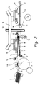
- Fig. 3
- einen Schnitt durch die Darstellung gemäß der Linie C-D;
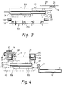
- Fig. 4
- einen Schnitt durch die Darstellung gemäß der Linie E-F;
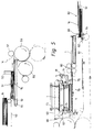
- Fig. 5
- ein zweites Ausführungsbeispiel einer Buchdeckenmaschine in einer Seitenansicht.
- Fig. 1
- a first embodiment of a book cover machine in a plan view;
- Fig. 2
- a section through the representation along the line AB;
- Fig. 3
- a section through the representation along the line CD;
- Fig. 4
- a section through the representation along the line EF;
- Fig. 5
- a second embodiment of a book cover machine in a side view.
In der Buchdeckenmaschine gemäß dem ersten Ausführungsbeispiel wird in bekannter Weise das Überzugsmaterial 1a, im folgenden als Nutzen bezeichnet, aus einem Magazin 2 einer Anlegestation durch Sauger 3 entnommen und einem Nutzenzylinder 4 zugeführt, der einen Nutzen 1a mit seinen Greifern 4a im Stillstand erfaßt und an einer Leimwalze 5 vorbeiführt. Nach ausgeführtem vollflächigen Beleimen übernimmt ein gradlinig vor- und zurückfahrbarer Greiferbalken 6 den beleimten Nutzen 1a im Stillstand vom Nutzenzylinder 4 und legt ihn auf einem Deckentisch 7 ab. Dieser ist mit einer Auflage 8 aus einem elastischen Material beschichtet und läßt sich um eine Horizontalachse 9, auf der der Deckentisch über ein Langloch 12 gelagert ist, zwischen einer unteren und einer oberen Endstellung verschwenken, wozu der Deckentisch 7 auf der freien Seite mit einem Ausleger 10 in einer Rollenbahn geführt und über nicht dargestellte Antriebsmittel betätigt wird.In the book cover machine according to the first embodiment, the covering
Zwischen dem Deckentisch 7 und einem Bereitstellungsplatz 11 für die Deckenpappen, bestehend aus den beiden Seitenteilen 1b sowie der Rückeneinlage 1c, auch Schrenz genannt, befindet sich ein um eine Vertikalachse 13 drehbarer sowie in Vertikalebene auf und ab bewegbarer Transportarm 14.Between the ceiling table 7 and a
Aus Magazinen 16 auf der dem Nutzenmagazin gegenüberliegenden Seite werden die beiden Deckenpappen 1b von Transporteuren 17 in den Bereitstellungsplatz 11 befördert, während die Rückeneinlage 1c von der Rolle zugeführt und mittels eines Schneidwerkes 18 abgelängt wird.From
Der zwischen dem Bereitstellungsplatz 11 und dem Deckentisch 7 durch Drehbewegung verfahrbarer Transportarm 14 nimmt über die Saugplattenanordnung 15 die bereitgestellten Pappen 1b und 1c auf und führt diese dem Deckentisch 7 zu, der sich in einer zu den Pappen 1b und 1c schräg verlaufenden Übernahmestellung befindet. Nach Beendigung der Drehbewegung senkt sich der Transportarm 14 und die von der Saugplattenanordnung 15 gehaltenen Pappen 1b und 1c werden mit dem Nutzen 1a zunächst an der Kopfeinschlagseite in Kontakt gebracht. Durch Abschwenkbewegung des Deckentisches 7 in die untere Endstellung in zeitlicher Übereinstimmung mit der weiteren Absenkbewegung des Transportarmes 14 nimmt der von den Pappen 1b und 1c und dem auf dem Deckentisch 7 aufliegenden Nutzen 1a eingeschlossene Winkel fortschreitend ab, dabei wandert die Kontaktlinie von der Kopfseite der Decke 1 zur Fußseite. Es ergibt sich somit ein Anwalzen des Nutzens 1a an die Pappen 1b und 1c. Unmittelbar vor Beendigung des Vortransportes des Nutzens 1a auf den Deckentisch 7 mittels des Greiferbalkens 6 drücken Niederhaltefinger 19 den Nutzen 1a im Bereich des Fußeinschlags gegen den Deckentisch 7, was zum Straffhalten des Nutzens führt. Unter Vermeidung von Lufteinschlüssen werden somit die Pappen 1b und 1c und das Überzugsmaterial 1a passergenau zusammengefügt.The
Erfindungsgemäß befindet sich getrennt von der Station zum Zusammenfügen von Pappen 1b, 1c und Nutzen 1a eine Einschlagstation mit in vertikal versetzten Ebenen angeordneten Einschlagelementen zum Ausführen der Kopf- und Fußeinschläge in einer ersten Ebene und zum Ausführen der Seiteneinschläge in einer zweiten Ebene. Dabei sind die Funktionen Zusammenfügen von Deckennutzen 1a und Deckenpappen 1b, Kopf- und Fußeinschlag sowie Seiteneinschlag derart aufeinander abgestimmt, daß alle Funktionen innerhalb eines Taktes gleichzeitig an verschiedenen Buchdecken erfolgen, so daß für jeden Vorgang einschließlich der Transportbewegung ein Maschinentakt zur Verfügung steht.According to the invention, separate from the station for assembling
Eine Transporteinrichtung in Form einer Saugleiste 22 mit daran über die Deckenlänge verteilten, abständig zueinander positionierten Saugern 23 erfaßt die aus den Pappen 1b, 1c und Nutzen 1a zusammengefügte Decke 1 einseitig auf ihrer ganzen Seitenlänge, um sie gestreckt der Einschlagstation zuzuführen. Dabei wird die Decke 1 auf der den Saugern 23 gegenüberliegenden Seite durch eine in die Bewegungsbahn und zurück steuerbare Stützschiene 24 unterfangen.A transport device in the form of a
Die Saugleiste 22 mit den Saugern 23 befindet sich an einem Wagen 25 mit auf eine Führungsbahn 27 greifenden Laufrollen 26 und wird von einem Antriebssystem 28 hin- und hergehend verfahren.The
In der Endposition der Einschlagstation übernehmen in der Zufuhrebene Saugschienen 29 die Decke 1 in den seitennahen Bereichen. Die Saugschienen 29 lassen sich über vertikale Führungsstangen 30 gemäß Pfeilrichtung höhen verfahren und können somit die Decke 1 gegen Druckschienen 31 drücken nach Zurückbewegen der Stützschiene 24 durch einen geringfügigen Abwärtshub. In einer abgewandelten Ausführung können die Druckschienen 31 auch unterhalb der Einschlagschiene 35 verbleiben und die Saugschienen 29 übernehmen den Vertikaltransport.In the end position of the wrapping station,
Die Abwärtsbewegung erfolgt bis in eine Position, in der sich die Oberkante der Deckenpappen 1b und 1c unterhalb der Einschlagschienen 35 befindet. In dieser Position fahren die Einschlagschienen 35 gemäß Pfeilrichtung einwärts, die Saugschienen 29 heben ab und die Druckschienen 31 drücken die Decke zum Erreichen eines strammen Einschlags gegen die sich noch einwärts bewegenden Einschlagschienen 35. Gleichzeitig mit dem Einschlagen erfolgt das Einziehen der Ecken über Eckeneinziehelemente 33, die von den Einschlagschienen 35 geführt sind. Die Druckschienen 31 lösen sich von der Decke und bewegen sich gemäß Pfeilrichtung auswärts, um der Decke 1 für eine weitere Abwärtsbewegung in die sich darunter befindliche Seiteneinschlagstation den Weg frei zu geben.The downward movement takes place in a position in which the upper edge of the
Hierzu erfolgt eine Übernahme der Decke 1 in der Ebene des Kopf- und Fußeinschlags durch höhenverfahrbare erste Teilstücke 36a von parallel über die Deckenlänge verteilt angeordneten Saugleisten, die die Decke 1 zunächst auf eine Zwischenebene verbringen, in der zweite höhenverfahrbare Teilstücke 36b die Decke 1 übernehmen, um sie gemeinsam mit den ersten Teilstücken 36a bis in die Ebene, in der die Seiteneinschläge ausgeführt werden, abzusenken. Auf dem Weg von der Zwischenebene zur Ebene für die Seiteneinschläge erfolgt das Aufrichten der seitlichen Überstände der Decke 1 an Aufrichtschienen 37.For this purpose, the
Das Umlegen der Seiteneinschläge vollzieht sich in bekannter Weise durch Einwärtsfahren von Seiteneinschlagschienen 38 unter Ausübung eines Anpreßdruckes durch die Saugleisten 36a, 36b.The flipping of the side turns takes place in a known manner by driving in side turning rails 38 while exerting a contact pressure by the suction strips 36a, 36b.
Nach dem Umlegen der Seiteneinschläge senken sich die Saugleisten 36a, 36b und legen die Decke 1 auf ein Transportsystem 39, 40 ab zum Abtransport der Decke 1 durch Transporteure 39 einer Ausfuhrkette 40 in ein nachgeordnetes Andrückwalzenpaar 41 sowie auf ein sich daran anschließendes Ausfuhrband 42.After the side turns have been folded over, the suction strips 36a, 36b lower and place the
In der Buchdeckenmaschine gemäß dem zweiten Ausführungsbeispiel werden Deckenpappen 1b auf einem Pappenvorstapelband 50 angelegt und automatisch in ein Pappenmagazin 51 verbracht, in dem die Vorderkante, gebildet von Anschlägen 52 mit Durchlaßleistenfunktion, verstellbar ist. Im Pappenmagazin 51 werden die Pappen 1b durch einen Kurzhubschieber 53 vereinzelt und vor Transporteure 54 an seitlichen Zahnriemen 55 gelegt. Dazu läuft der Schieber 53 leicht schräg nach unten. Der Rückhub erfolgt sofort, wodurch eine Stapelentlastung stattfindet. Die Eingriffshöhe der Transporteure 54 wird durch Höheneinstellungen nicht dargestellter Führungsschienen justiert. Die Zahnriemen laufen kontinuierlich mit Taktgeschwindigkeit und übergeben die Pappen 1b synchron an einen Nutzenzylinder 56 mit einer Oberwalze 57. Zur Justierung auf Formathöhe erfolgt eine Taktverstellung des gesamten Pappentransportantriebs und eine Verstellung der Anschläge 52. Synchron mit der Pappenzufuhr kann eine Rückeneinlage 1c von einer nicht dargestellten Abzugseinrichtung kommend abgelängt und zugeführt werden.In the book cover machine according to the second exemplary embodiment, cover
Auf der der Pappenzufuhr gegenüberliegenden Seite erfolgt die Zufuhr der Deckenbezüge 1a, nachfolgend wiederum als Nutzen bezeichnet, und zwar durch umlaufende Greiferbalken 60 eines Kettensystems 61 unmittelbar an den Nutzenzylinder 56. Die Nutzen 1a gelangen z. B. in Form einer Schuppe von einem Vorstapelband 62 in ein Nutzenmagazin 63, aus dem sie nach unten durch eine Saugerleiste 64 abgekippt und durch eine Synchronbewegung der Saugerleiste 64 in Transportrichtung an die Greiferbalken 60 übergeben werden. Durch Blasluft kann der Nützenstapel aufgelockert werden, um Rolleffekte zu vermeiden. Die Vorschubsteuerung der in Schuppenformation vorliegenden Nutzen 1a erfolgt über Lichttaster 65.On the side opposite the cardboard feeder, the
Der von Nutzenzylinder 56 und Oberwalze 57 mit den Deckenpappen 1b zusammengefügte, zuvor beim Passieren einer Beleimeinrichtung 66 flächig beleimte Nutzen 1a wird oberhalb von Stützrollen 67 gemeinsam mit den Pappen 1b, 1c von Greifen 68 eines Kettensystems 69 synchron übernommen und in die Einschlagstation verbracht, wobei eine kontrollierte Verzögerung des Kettensystems 69 erfolgt. Über nicht dargestellte Stützleisten werden die Buchdecken auf Höhe gehalten, damit obere Sauger 70 die Buchdecke während des Stillstandes des Kettensystems 69 übernehmen können.The
Durch einen Abwärtshub bringen die Sauger 70 die Buchdecke in die Kopf-und Fußeinschlagebene und legen sie auf ausgefahrene Druckschienen 71 ab. Während der Abwärtsbewegung erfolgt das Aufrichten der Kopf- und Fußeinschläge an ortsfesten Aufrichtschienen 73.By means of a downward stroke, the
Einschlagschienen 72 vollführen danach nun den Kopf- und Fußeinschlag während die Sauger 70 wieder in ihre Ausgangsposition nach oben zurückkehren. Mit dem Kopf- und Fußeinschlag erfolgt das Eckeneinknicken über bekannte Eckeneinziehelemente.Wrapping rails 72 then perform the head and foot impact while the
Vor Abschluß des Kopf- und Fußeinschlags fahren untere Sauger 74 unter die Buchdecken, um diese nach Beendigung des Einschlags zu übernehmen und sie abwärts in die Seiteneinschlagebene zu transportieren, nachdem Druckschienen 71 und Einschlagschienen 72 zurückgezogen sind. Die Buchdecke wird auf seitliche Saugschienen 75 abgelegt, die zu diesem Zeitpunkt vorgeschoben sind und mit Saugern die Buchdecke halten. Über die Einschlagschiene 76 erfolgt nun der Seiteneinschlag, indem durch eine vertikale Bewegung der Einschlag aufgerichtet und durch eine darauffolgende horizontale Bewegung angerieben wird. Während der Einschlaghaltezeit weichen die Sauger 74 in Richtung Kopf und Fuß der Buchdecke aus dem Formatbereich aus, damit nach Zurückziehen der Saugschienen 75 und Einschlagschienen 76 die Buchdecke auf die Ausfuhrebene fallen kann. Die unteren Sauger 74 laufen nun mit einer schrägen Bewegung aufwärts in die Übernahmeposition der Kopf- und Fußeinschlagebene. Dabei wird durch Abweiser an den Saugern 74 die fertige Buchdecke zwangsläufig nach unten beschleunigt, damit der Transport in die Ausführebene nicht auf freien Fall angewiesen ist. Die Buchdecke fällt auf einen Auflagetisch 78 und wird dort durch eine konstant mit Taktgeschwindigkeit laufende Transportkette 79 in die Anrollstation 80 geschoben. Die unteren Sauger 74 führen eine Bewegung gemäß Pfeilrichtung aus, wozu sie über Antriebe 81 vertikal linear verfahrbar und horizontal verschwenkbar sind. Erfindungsgemäß werden auch in diese Ausführungsbeispiel einer Buchdeckenmaschine alle Funktionen innerhalb eines Taktes gleichzeitig an verschiedenen Buchdecken ausgeführt bzw. daß alle Arbeitsgänge in nacheinander folgenden Takten an einer Buchdecke vorgenommen werden.Before the end of the head and foot wrap,
Claims (11)
- Book cover machine with feeder stations for the cover coverings (1a) and cover boards (1b, 1c), with a glue-application arrangement for the cover coverings (1a), with an arrangement for assembling the cover coverings (1a) and cover boards (1b, 1c), with turn-in elements (31-33, 35; 71-73; 37, 38; 75, 76) for turning the head and foot turn-in flaps over the cover-board edges in a first plane, and for turning the lateral turn-in flaps over the cover board edges in a vertically displaced second plane, with means for transporting the cover coverings (1a), united with the cover boards (1b, 1c) into the region where the turn-in elements (31-33, 35; 71-73; 37, 38; 75, 76) operate, and with an arrangement for pressing the cover coverings (1a) and cover boards (1b, 1c), characterized by a turn-in station which is installed separately, beside the arrangement for assembling the cover coverings (1a) and cover boards (1b, 1c), said turn-in station having turn-in elements (31-33, 35; 71-73) for turning over the head and foot turn-in flaps in a first plane, and turn-in elements (37, 38; 75, 76) for turning over the lateral turn-in flaps in a vertically displaced second plane, by horizontally movable transport means (22-28; 68, 69) which have a transferring function, their purpose being to bring the cover coverings (1a) assembled with the cover boards (1b, 1c) into said turn-in station, and by vertically movable transport means (29, 30, 36a, 36b; 70, 74, 81) which have an acquiring function, their purpose being to bring the cover coverings (1a) assembled with the cover boards (1b, 1c) into the region where the turn-in elements (31-33, 35; 71-73; 37, 38; 75, 76) operate.
- Book cover machine according to Claim 1, characterized in that the functions of assembling the cover coverings (1a) and cover boards (1b, 1c), of executing the head and foot turn-ins, and of executing the lateral turn-ins, are coordinated one with another, such that all functions within a cycle are performed on different book covers (1a, 1b, 1c) simultaneously.
- Book cover machine according to Claim 1 or Claim 2, characterized by upper transport means (70; 29, 30) which have an acquiring function, their purpose being to bring the cover coverings (1a) and cover boards (1b, 1c) into the first turn-in plane, and lower transport means (74, 81; 36a, 36b) which have an acquiring function, their purpose being to transport the cover coverings (1a) and cover boards (1b, 1c) from the first turn-in plane and bring them into the vertically displaced second turn-in plane.
- Book cover machine according to any one of Claims 1 to 3, characterized in that the lower transport means (74) which have an acquiring function can be caused to execute vertical linear movements and horizontal swinging movements through the agency of drive arrangements (81).
- Book cover machine according to any of Claims 1 to 3, characterized by a cover table (7) which can be swung about a horizontal axle (9) and can be transferred, with a cover covering (1a) which has been supplied, from a position inclined to the cover boards (1b, 1c) which are held by a transport arm (14), to a position parallel with said cover boards (1b, 1c), and as this swinging movement occurs, the angle included by said cover boards (1b 1c, ) and the cover covering (1a) progressively diminishes and at the same time the transport arm (14) descends in synchronism with said swinging movement of the cover table (7).
- Book cover machine according to any one of Claims 1 to 3, 5, characterized in that the cover table (7) is provided with a facing layer (8), composed of a resilient material.
- Book cover machine according to any one of Claims 1 to 3, 5 to 6, with turn-in rails for turning up and turning over the head and foot turn-in flaps, characterized by suction rails (29) which hold the cover covering (1a) and the cover boards (1b, 1c) in the areas near the sides, and which have pressure rails (31) assigned to them, and these can together be moved from a plane in which the cover boards (1b, 1c) and cover covering (1a) are supplied, into a plane that is vertically displaced in the downward direction, as far as a position at which the cover boards (1b, 1c) are immediately below the turn-in rails (35).
- Book cover machine according to any one of Claims 1 to 3, 5 to 7, characterized by suction rails which are each formed by two sections (36a, 36b), which are distributed over the cover length in an arrangement parallel with the head and foot turn-ins, and which are movable between a lower movement limit position, for turning over the lateral turn-in flaps, and an upper movement limit position, while in order to acquire the cover (1) the group comprising certain sections (36a) can be raised to the plane in which the head and foot turn-ins are executed, and the group comprising the other sections (36b) can be raised as far as an intermediate plane, and the sections (36a, 36b) together transfer the cover (1) from the intermediate plane to the lower movement limit position.
- Book cover machine according to any one of Claims 1 to 3, 5 to 8, characterized in that the transport means (22, 23) grip the cover boards (1b, 1c) and the cover covering (1a) at a longitudinal side, and said cover boards (1b, 1c) and cover covering (1a) are supported from underneath, at the opposite longitudinal side, by supporting rails (24) which can be moved into the movement path and back again.
- Book cover machine according to any one of Claims 1 to 3, 5 to 9, characterized by hold-down fingers (19) which press the rear edge area of the cover covering (1a), as viewed in the ingoing direction, against the cover table (7), so as to exert a tensioning effect during the forward transport.
- Book cover machine according to any one of Claims 1 to 4, characterized by a cover covering magazine (63) which is located on the side opposite the board magazine (51), and a coveying system (61) which runs below the turn-in station, between the cover covering magazine (63) and a cloth cylinder (56) which is assigned to said board magazine (51).
Applications Claiming Priority (4)
| Application Number | Priority Date | Filing Date | Title |
|---|---|---|---|
| DE4241387 | 1992-12-09 | ||
| DE4241387 | 1992-12-09 | ||
| DE4308469 | 1993-03-17 | ||
| DE4308469A DE4308469A1 (en) | 1992-12-09 | 1993-03-17 | Book cover machine |
Publications (2)
| Publication Number | Publication Date |
|---|---|
| EP0603501A1 EP0603501A1 (en) | 1994-06-29 |
| EP0603501B1 true EP0603501B1 (en) | 1997-03-19 |
Family
ID=25921121
Family Applications (1)
| Application Number | Title | Priority Date | Filing Date |
|---|---|---|---|
| EP93117531A Expired - Lifetime EP0603501B1 (en) | 1992-12-09 | 1993-10-29 | Machine for manufacturing book covers |
Country Status (3)
| Country | Link |
|---|---|
| US (1) | US5413446A (en) |
| EP (1) | EP0603501B1 (en) |
| JP (1) | JPH06210981A (en) |
Families Citing this family (22)
| Publication number | Priority date | Publication date | Assignee | Title |
|---|---|---|---|---|
| US5634633A (en) * | 1995-11-22 | 1997-06-03 | Quad/Tech, Inc. | Apparatus and method for securing an item to printed material |
| US6302388B1 (en) | 1995-11-22 | 2001-10-16 | Quad/Graphics, Inc. | Apparatus and method for securing an item to a cover of printed material |
| US5988620A (en) * | 1995-11-22 | 1999-11-23 | Quad/Tech, Inc. | Apparatus and method for personalizing printed materials |
| US5827033A (en) * | 1996-06-06 | 1998-10-27 | James D. Welch | Case making dies and systems, and methods of adjustment, alignment and use thereof |
| US6494661B1 (en) * | 2000-05-12 | 2002-12-17 | Heidelberger Druckmaschinen Ag | Device and method for providing a cover for a book |
| ES2330191T3 (en) | 2000-05-19 | 2009-12-07 | Maping Kommandiittiyhtio L. Huotari | METHOD AND DEVICE FOR MANUFACTURING THE COVERS OF A BOOK OR EQUVALENT. |
| US6379094B1 (en) | 2000-05-24 | 2002-04-30 | Thomas Porat | Apparatus for tucking hard book covers |
| DE10057599C5 (en) * | 2000-11-21 | 2015-02-19 | Kolbus Gmbh & Co. Kg | Device for making book covers |
| DE10057600B4 (en) * | 2000-11-21 | 2008-10-09 | Kolbus Gmbh & Co. Kg | Device for feeding back inserts for the manufacture of book covers |
| AU2003272395A1 (en) * | 2002-09-13 | 2004-04-30 | Gp2 Technologies, Inc. | Apparatus and method for manufacturing hard book cover assemblies |
| DE102005051477A1 (en) * | 2005-10-24 | 2007-04-26 | Michael Hörauf Maschinenfabrik GmbH & Co. KG | Method for covering flat-lying blank, particularly made of cardboard with cover, particularly applicable in production of book covers, involves carrying out covering in cycles in multiple working stations |
| FI117825B (en) * | 2006-01-25 | 2007-03-15 | Maping Ky L Huotari | Surface film folding method for book cover, involves inserting cover between rollers to fold film edge onto cover inner surface through pressure of rollers |
| DE102007018023A1 (en) * | 2007-04-17 | 2008-10-23 | Peter Schmidkonz | Method and device for the manufacture of book covers for individual books and short runs of different format sizes |
| US8123449B2 (en) * | 2007-11-05 | 2012-02-28 | Gp2 Technologies, Inc. | Single axis apparatus for manufacturing hard book cover |
| DE102007057228A1 (en) * | 2007-11-28 | 2009-06-04 | Kolbus Gmbh & Co. Kg | Device for transferring a book cover from a roll-on device to a transfer point |
| JP5208574B2 (en) * | 2008-05-14 | 2013-06-12 | ホリゾン・インターナショナル株式会社 | Cover folding machine |
| DE102010024232A1 (en) * | 2010-06-18 | 2011-12-22 | Kolbus Gmbh & Co. Kg | Method and device for producing book covers |
| DE102011003348A1 (en) * | 2011-01-28 | 2012-08-02 | Maping Kommandiittiyhtiö L. Huotari | Device for manufacturing large-format hard cover of book for bookbinding, has balancing unit and limiter provided in front part of table-like part, and envelope aligned on table-like part with movement coming in direction of front part |
| ITMI20111016A1 (en) * | 2011-06-06 | 2012-12-07 | Sitma Machinery S P A | GROUP AND METHOD FOR THE CONTINUOUS REALIZATION OF OVERHAPPENSINES OF VARIOUS DIMENSIONS STARTING FROM A FILM WRAPPED INTO THE COIL |
| ITTO20120175A1 (en) * | 2012-02-27 | 2013-08-28 | Smyth S R L | METHOD AND MACHINE FOR THE CONSTRUCTION OF RIGID COVERS FOR BOOKS |
| CN114599523B (en) * | 2019-09-10 | 2023-05-09 | 深圳市高登设备有限公司 | Full-automatic book mouth tightening device |
| US11787218B1 (en) * | 2023-02-14 | 2023-10-17 | Lightning Source LLC | Book cover embossing system and method |
Family Cites Families (4)
| Publication number | Priority date | Publication date | Assignee | Title |
|---|---|---|---|---|
| US2501733A (en) * | 1948-12-03 | 1950-03-28 | Herman A Merz | Case turning-in machine |
| US2556787A (en) * | 1949-02-12 | 1951-06-12 | Florez Company Inc De | Register control for web fed casemaking machines |
| US3237223A (en) * | 1963-06-22 | 1966-03-01 | Smyth Europea Spa | Book-cover manufacturing machine |
| DE3817993C2 (en) * | 1987-07-10 | 1999-06-17 | Kolbus Gmbh & Co Kg | Wrapping device for a machine for producing book cover covers |
-
1993
- 1993-10-29 EP EP93117531A patent/EP0603501B1/en not_active Expired - Lifetime
- 1993-12-03 US US08/162,536 patent/US5413446A/en not_active Expired - Lifetime
- 1993-12-08 JP JP5308102A patent/JPH06210981A/en not_active Ceased
Also Published As
| Publication number | Publication date |
|---|---|
| JPH06210981A (en) | 1994-08-02 |
| EP0603501A1 (en) | 1994-06-29 |
| US5413446A (en) | 1995-05-09 |
Similar Documents
| Publication | Publication Date | Title |
|---|---|---|
| EP0603501B1 (en) | Machine for manufacturing book covers | |
| EP0386524B1 (en) | Device for packaging objects of different size | |
| EP0187344B1 (en) | Method and device for the production of single stacks consisting of a fan folded web | |
| CH458187A (en) | Device for packing goods | |
| DE3937995C2 (en) | Method and device for separating sheets and storing them in a giant | |
| DE3813729A1 (en) | STACKING OF BANDS OF FLAT-FOLDED BOXES MADE OF CORRUGATED CARDBOARD | |
| DE2151466A1 (en) | Device for processing sheets | |
| DE4141767A1 (en) | METHOD AND ARRANGEMENT FOR PRODUCING BOOKS AND BROCHURES | |
| DE3321756A1 (en) | DEVICE FOR STACKING CUTS | |
| DE19839924A1 (en) | Foil suction lift and positioning frame for chipboard and fibreboard production is lighter than prior art, facilitating higher operating speed | |
| DE10057599A1 (en) | Device for manufacturing book binding covers has mutually independent drives for at least cover element transport arrangement, board transport arrangement, insertion/pressure arrangement | |
| DE10057602A1 (en) | Bookbinding cover producing device has material flow of boards and covers rising towards horizontal resting surface of machine | |
| EP1428679A2 (en) | Book press machine | |
| DE3911969A1 (en) | DEVICE FOR GIANTLY PUTTING SHEETS, IN PARTICULAR PAPER SHEETS, ONTO A PACK | |
| DE3817993C2 (en) | Wrapping device for a machine for producing book cover covers | |
| EP0243944A1 (en) | Device for the production of bundled piles of folded paper sheets | |
| DE1461826A1 (en) | Package forming machine | |
| EP0603502B1 (en) | Machine for manufacturing book covers | |
| DE4308469A1 (en) | Book cover machine | |
| DE2618950A1 (en) | PLATE TRANSFER MACHINE | |
| DE3931710A1 (en) | Non-stop sheet feeder for rotary printing machines - has stacking plate movable from horizontal to inclined position | |
| DE2949896C2 (en) | Device for stacking folding boxes coming from a folding box gluing machine | |
| DE2731900A1 (en) | DEVICE AND METHOD OF PACKING UNITS IN CONTAINERS | |
| DE19839923C2 (en) | Device for removing films from a film stack in a stacking station and for storing the removed films in a folding station | |
| DE2846020A1 (en) | DEVICE FOR FILLING PAPER STACKS IN BOXES |
Legal Events
| Date | Code | Title | Description |
|---|---|---|---|
| PUAI | Public reference made under article 153(3) epc to a published international application that has entered the european phase |
Free format text: ORIGINAL CODE: 0009012 |
|
| AK | Designated contracting states |
Kind code of ref document: A1 Designated state(s): CH DE FR GB IT LI |
|
| 17P | Request for examination filed |
Effective date: 19940719 |
|
| GRAG | Despatch of communication of intention to grant |
Free format text: ORIGINAL CODE: EPIDOS AGRA |
|
| GRAH | Despatch of communication of intention to grant a patent |
Free format text: ORIGINAL CODE: EPIDOS IGRA |
|
| GRAH | Despatch of communication of intention to grant a patent |
Free format text: ORIGINAL CODE: EPIDOS IGRA |
|
| 17Q | First examination report despatched |
Effective date: 19960219 |
|
| GRAA | (expected) grant |
Free format text: ORIGINAL CODE: 0009210 |
|
| AK | Designated contracting states |
Kind code of ref document: B1 Designated state(s): CH DE FR GB IT LI |
|
| REG | Reference to a national code |
Ref country code: CH Ref legal event code: EP |
|
| ET | Fr: translation filed | ||
| REF | Corresponds to: |
Ref document number: 59305868 Country of ref document: DE Date of ref document: 19970424 |
|
| GBT | Gb: translation of ep patent filed (gb section 77(6)(a)/1977) |
Effective date: 19970415 |
|
| ITF | It: translation for a ep patent filed |
Owner name: MODIANO & ASSOCIATI S.R.L. |
|
| PLBE | No opposition filed within time limit |
Free format text: ORIGINAL CODE: 0009261 |
|
| STAA | Information on the status of an ep patent application or granted ep patent |
Free format text: STATUS: NO OPPOSITION FILED WITHIN TIME LIMIT |
|
| 26N | No opposition filed | ||
| REG | Reference to a national code |
Ref country code: CH Ref legal event code: NV Representative=s name: A. BRAUN, BRAUN, HERITIER, ESCHMANN AG PATENTANWAE |
|
| PGFP | Annual fee paid to national office [announced via postgrant information from national office to epo] |
Ref country code: FR Payment date: 20010718 Year of fee payment: 9 |
|
| PGFP | Annual fee paid to national office [announced via postgrant information from national office to epo] |
Ref country code: GB Payment date: 20011031 Year of fee payment: 9 |
|
| REG | Reference to a national code |
Ref country code: GB Ref legal event code: IF02 |
|
| PG25 | Lapsed in a contracting state [announced via postgrant information from national office to epo] |
Ref country code: GB Free format text: LAPSE BECAUSE OF NON-PAYMENT OF DUE FEES Effective date: 20021029 |
|
| GBPC | Gb: european patent ceased through non-payment of renewal fee | ||
| PG25 | Lapsed in a contracting state [announced via postgrant information from national office to epo] |
Ref country code: FR Free format text: LAPSE BECAUSE OF NON-PAYMENT OF DUE FEES Effective date: 20030630 |
|
| REG | Reference to a national code |
Ref country code: FR Ref legal event code: ST |
|
| PG25 | Lapsed in a contracting state [announced via postgrant information from national office to epo] |
Ref country code: IT Free format text: LAPSE BECAUSE OF NON-PAYMENT OF DUE FEES;WARNING: LAPSES OF ITALIAN PATENTS WITH EFFECTIVE DATE BEFORE 2007 MAY HAVE OCCURRED AT ANY TIME BEFORE 2007. THE CORRECT EFFECTIVE DATE MAY BE DIFFERENT FROM THE ONE RECORDED. Effective date: 20051029 |
|
| PGFP | Annual fee paid to national office [announced via postgrant information from national office to epo] |
Ref country code: DE Payment date: 20071004 Year of fee payment: 15 |
|
| PGFP | Annual fee paid to national office [announced via postgrant information from national office to epo] |
Ref country code: CH Payment date: 20071024 Year of fee payment: 15 |
|
| REG | Reference to a national code |
Ref country code: CH Ref legal event code: PFA Owner name: KOLBUS GMBH & CO. KG Free format text: KOLBUS GMBH & CO. KG#OSNABRUECKER STRASSE 77#D-32369 RAHDEN (DE) -TRANSFER TO- KOLBUS GMBH & CO. KG#OSNABRUECKER STRASSE 77#D-32369 RAHDEN (DE) |
|
| REG | Reference to a national code |
Ref country code: CH Ref legal event code: PL |
|
| PG25 | Lapsed in a contracting state [announced via postgrant information from national office to epo] |
Ref country code: DE Free format text: LAPSE BECAUSE OF NON-PAYMENT OF DUE FEES Effective date: 20090501 |
|
| PG25 | Lapsed in a contracting state [announced via postgrant information from national office to epo] |
Ref country code: LI Free format text: LAPSE BECAUSE OF NON-PAYMENT OF DUE FEES Effective date: 20081031 Ref country code: CH Free format text: LAPSE BECAUSE OF NON-PAYMENT OF DUE FEES Effective date: 20081031 |