EP0603473A2 - Thermal ink-jet pen with a plastic/metal attachment for the cover - Google Patents
Thermal ink-jet pen with a plastic/metal attachment for the cover Download PDFInfo
- Publication number
- EP0603473A2 EP0603473A2 EP93114942A EP93114942A EP0603473A2 EP 0603473 A2 EP0603473 A2 EP 0603473A2 EP 93114942 A EP93114942 A EP 93114942A EP 93114942 A EP93114942 A EP 93114942A EP 0603473 A2 EP0603473 A2 EP 0603473A2
- Authority
- EP
- European Patent Office
- Prior art keywords
- cover
- frame structure
- tabs
- ink
- frame
- Prior art date
- Legal status (The legal status is an assumption and is not a legal conclusion. Google has not performed a legal analysis and makes no representation as to the accuracy of the status listed.)
- Granted
Links
Images


Classifications
-
- B—PERFORMING OPERATIONS; TRANSPORTING
- B41—PRINTING; LINING MACHINES; TYPEWRITERS; STAMPS
- B41J—TYPEWRITERS; SELECTIVE PRINTING MECHANISMS, i.e. MECHANISMS PRINTING OTHERWISE THAN FROM A FORME; CORRECTION OF TYPOGRAPHICAL ERRORS
- B41J2/00—Typewriters or selective printing mechanisms characterised by the printing or marking process for which they are designed
- B41J2/005—Typewriters or selective printing mechanisms characterised by the printing or marking process for which they are designed characterised by bringing liquid or particles selectively into contact with a printing material
- B41J2/01—Ink jet
- B41J2/17—Ink jet characterised by ink handling
- B41J2/175—Ink supply systems ; Circuit parts therefor
- B41J2/17503—Ink cartridges
- B41J2/17513—Inner structure
-
- B—PERFORMING OPERATIONS; TRANSPORTING
- B41—PRINTING; LINING MACHINES; TYPEWRITERS; STAMPS
- B41J—TYPEWRITERS; SELECTIVE PRINTING MECHANISMS, i.e. MECHANISMS PRINTING OTHERWISE THAN FROM A FORME; CORRECTION OF TYPOGRAPHICAL ERRORS
- B41J29/00—Details of, or accessories for, typewriters or selective printing mechanisms not otherwise provided for
- B41J29/12—Guards, shields or dust excluders
- B41J29/13—Cases or covers
-
- Y—GENERAL TAGGING OF NEW TECHNOLOGICAL DEVELOPMENTS; GENERAL TAGGING OF CROSS-SECTIONAL TECHNOLOGIES SPANNING OVER SEVERAL SECTIONS OF THE IPC; TECHNICAL SUBJECTS COVERED BY FORMER USPC CROSS-REFERENCE ART COLLECTIONS [XRACs] AND DIGESTS
- Y10—TECHNICAL SUBJECTS COVERED BY FORMER USPC
- Y10T—TECHNICAL SUBJECTS COVERED BY FORMER US CLASSIFICATION
- Y10T29/00—Metal working
- Y10T29/49—Method of mechanical manufacture
- Y10T29/49401—Fluid pattern dispersing device making, e.g., ink jet
-
- Y—GENERAL TAGGING OF NEW TECHNOLOGICAL DEVELOPMENTS; GENERAL TAGGING OF CROSS-SECTIONAL TECHNOLOGIES SPANNING OVER SEVERAL SECTIONS OF THE IPC; TECHNICAL SUBJECTS COVERED BY FORMER USPC CROSS-REFERENCE ART COLLECTIONS [XRACs] AND DIGESTS
- Y10—TECHNICAL SUBJECTS COVERED BY FORMER USPC
- Y10T—TECHNICAL SUBJECTS COVERED BY FORMER US CLASSIFICATION
- Y10T29/00—Metal working
- Y10T29/49—Method of mechanical manufacture
- Y10T29/49826—Assembling or joining
- Y10T29/49863—Assembling or joining with prestressing of part
- Y10T29/49876—Assembling or joining with prestressing of part by snap fit
Definitions
- the present invention is related to the following commonly assigned pending U.S. patent applications: COMPACT FLUID COUPLER FOR THERMAL INK JET PRINT CARTRIDGE INK RESERVOIR, serial number 07/853,372, filed March 18, 1992, by James G. Salter et al.; INK PRESSURE REGULATOR FOR A THERMAL INK-JET PRINTER, serial number 07/928,811, filed August 12, 1992, by Tofigh Khodapanah et al.; COLLAPSIBLE INK RESERVOIR STRUCTURE AND PRINTER INK CARTRIDGE, serial number 07/929,615, filed August 12, 1992, by George T.
- the present invention relates to thermal ink-jet (TIJ) pens, and more particularly to a technique for attachment of a metal cover to the pen.
- TIJ technology is widely used in computer printers.
- a TIJ includes a print head typically comprising several tiny controllable ink-jets, which are selectively activated to release a jet or spray of ink from an ink reservoir onto the print media (such as paper) in order to create an image or portion of an image.
- TIJ printers are described, for example, in the Hewlett-Packard Journal, Volume 36, Number 5, May, 1985, and Volume 39, Number 4, August, 1988.
- An object of this invention is to provide a TIJ pen which includes an external pen frame structure fabricated of plastic, and a metal cover which is attached to the plastic frame structure to enclose an open region defined by the frame and protect an ink reservoir within the TIJ pen.
- a further object is to provide a technique for rigidly attaching a metal cover to a plastic frame without the use of adhesives, screws, thermal, or ultrasonic processes.
- a thermal ink-jet pen comprises an external pen frame structure fabricated of a plastic material and a metal cover attached to the frame structure.
- the frame structure defines the external periphery of the pen and large open regions at the sides thereof.
- An ink reservoir is mounted within the frame structure, and a thermal ink-jet printhead is coupled to the ink reservoir.
- the metal cover comprises a planar surface member for covering the open region defined by the frame. Means are provided for attaching the metal cover to the plastic frame structure, wherein the cover encloses the open region and protects the ink reservoir.
- the frame structure defines two large open regions, one on each pen side, and there are two metal covers attached to the frame, one covering each open region.
- the frame structure comprising a plurality of tab mating features.
- the metal cover comprises a planar surface and has a plurality of spaced metal tabs projecting from the planar surface for engagement with the mating features of the frame structure.
- the tabs are press fit into engagement with the mating features of the frame structure such that the tabs displace plastic on the mating features. As a result, the tabs become locked into the frame features, and thereby secure the cover to the frame structure without adhesives, screws, thermal, or ultrasonic processes.
- the tab includes an end portion which is enlarged with respect to the tab body, so that the end portion displaces plastic defining the mating features when the cover is attached.
- the mating features comprise a slot formed in the frame, the slot having a width dimension smaller than the enlarged end portion of the tab, wherein as the tab is press fit into the slot, plastic surrounding the slot is displaced.
- the slot further includes beveled sides presenting plastic material at the sides which is displaced as the tab is press fit into the slot.
- FIGS. 1-9 illustrate a TIJ pen 50 embodying the invention.
- the pen comprises an external frame structure 60, and a pair of side covers 70 and 80.
- the frame 60 defines the external periphery of the pen 50 as a narrow, flat structure.
- the TIJ pen 50 provides many benefits for the printing system built to utilize it.
- the pen 50 is narrow reducing the required width of the printer carriage and therefore the total printer width.
- the pen 50 includes a simple and efficient ink delivery system, more fully described in the above-reference pending applications, serial nos. 07/928,811 and 07/929,615.
- ink is contained within a reservoir formed by two pieces of thin polyethylene bag material 62 bonded to a compatible plastic material on the frame 60.
- Two pistons and a spring (not shown) inside the bag provide backpressure to prevent ink from drooling out the printhead 52.
- the frame 60 is made of two different plastic materials.
- the first material is an engineering plastic forming the external surfaces and providing structural support.
- An exemplary plastic suitable for the purpose is polyphenyleneoxide (PPO).
- PPO polyphenyleneoxide
- the second plastic material provides the fluid path for the ink and is suitable for attachment of the bag material, as described more fully in the above-referenced pending application serial number 07/853,372.
- the covers 70 and 80 may be fabricated of any suitable material; in this exemplary embodiment, the covers are fabricate of metal.
- the thin metal side covers 70 and 80 protect the inside components, add considerable rigidity to the system, and allow for a high degree of volumetric efficiency.
- the covers 70 and 80 can be fabricated of a pre-processed metal, such as metal having a pre-painted surface or a PVC clad metal to provide an aesthetically complete appearance.
- the covers 70 and 80 must be rigid to prevent ink from being squeezed out in the event force is applied against the covers, e.g., during handling of the pen.
- An exemplary material from which the covers 70 and 80 may be fabricated is low carbon steel having a thickness of 0.019 inches.
- the metal covers 70 and 80 may be attached to the plastic frame 60 by adhesives or screw fasteners, or by use of thermal or ultrasonic processes.
- the problem of attaching a cover to a thin plastic frame is solved by designing a series of metal tabs on the covers that will lock onto mating plastic features on the frame.
- the tabs displace plastic on the mating features of the frame during assembly, allowing use of a simple mechanical press to assemble the covers to the frame, with no adhesives, screws, thermal or ultrasonic processes.
- the design of the cover tabs also enables them to lock into the frame; and the addition of chamfered corners on the tab aids assembly by providing a lead-in surface.
- the resulting cover/frame seam will resist shear, axial and transverse forces that occur in the joint as a result of externally applied loads to the pen.
- This joint allows for use of cosmetically suitable cover materials (e.g., pre-painted metal, PVC clad metal, or metals having a suitable cosmetic surface).
- the cover 70 includes a series of spaced tabs 72 which are designed to mate into corresponding dovetailed slot features 64 defined in the frame 60.
- the cover 80 is a mirror image of the cover 70, and also includes spaced metal tabs 82 which are designed to mate into corresponding dovetailed slot features (not shown) in an edge of the frame 60 similar to the slots 64. Because the attachment technique for the two covers 70 and 80 is identical, only the attachment of cover 70 will be described in detail.
- FIG. 2 shows the cover 70 attached to the frame 60, wherein the cover tabs have been partially press fit into the corresponding slot features 64 of the frame 60.
- the only assembly step remaining to the cover-frame configuration of FIG. 2 is to apply force to the cover to fully seat the tabs into the slot features.
- the frames 60 are preferably fabricated by injection molding. Typically the sides of a frame, before integration with the cover, will be bowed slightly inwardly. Similarly, the tabs 72 of a typical cover 70 after fabrication will not be bent exactly perpendicular to the cover surface, but will instead be bent outwardly to a degree.
- special tooling is employed. This tooling acts to force the top edges of the frame sides outwardly to receive the cover, and forces the tabs into a true perpendicular position relative to the cover surface. As a result, the tabs are properly aligned with the dovetailed slots 64 formed in the frame sides, and force can be applied to press fit the tabs into engagement with the slots. Exemplary tooling to accomplish these functions is shown in FIG. 3.
- FIG. 3 illustrates a mechanical press arrangement for press fitting the cover tabs into engagement with the slot features 64 of the frame 60, to result in the partially assembled cover-frame configuration as shown in FIG. 2.
- a tool 100 includes an arm 102 with an blade tip 104.
- a dogleg section 106 pivots about pivot point 108.
- the arm 102 and dogleg section 106 are connected by a pin 105 fixed to the section 106 and extending through a slot 107 formed in the arm 102.
- the arm 102 in turn rides in a slot 103 defined in tooling block 109.
- a double acting pneumatic cylinder 110 has a piston rod 112 which is connected to the intermediate area of the dogleg section at point 114. Actuation of the cylinder 110 then causes extension or retraction of the piston 112, thereby driving the dogleg section 106 to pivot upwardly or downwardly about the pivot point 108, in turn causing the arm 102 to slide upwardly or downwardly within slot 103.
- the tool 100 further includes an inclined block surface 116 and a vertical surface 117 which extends along the side of the cover. As the tabs 72 come into contact with these surfaces, those tabs which are splayed outwardly are bent into a perpendicular position relative to the cover surface.
- the blade tip 104 is employed to force the inwardly bowed top edge of the frame outwardly into alignment with the cover tabs.
- a press tool 120 is extended downwardly to contact the top surface of the cover 70, pressing the cover downwardly. At the commencement of the operation, the blade tip 104 is fully extended downwardly. The blade tip 104 is positioned so that it is intermediate two adjacent tabs 72.
- the cover 70 As the cover is pressed downwardly, the side of the frame 60 engages the blade tip 104, thereby applying pressure tending to bend the side outwardly as the cover is pressed downwardly. In the meantime, the tabs are aligned by engagement with the block surfaces 116 and 117, tending to align the tabs with the recessed features 64 formed in the frame 60. As the cover 70 continues to be pressed downwardly by the press tool 120, the blade tip 104 is withdrawn by actuation of the cylinder 110 to lift the blade tip away from engagement with the frame side, until the blade tip is fully retracted away from the side of the frame. This permits the cover 70 to be press fit into engagement with the frame features by continued downward pressure of the press tool 120.
- the press tool 120 does not apply sufficient force to fully seat the tabs into the slots 64, but rather only partially seats the tabs to the extent shown in FIG. 2.
- the partially assembled pen is then moved to another station where another press tool, capable of exerting a greater force, is applied to fully seat the tabs into the dovetailed slots.
- Another press tool capable of exerting a greater force, is applied to fully seat the tabs into the dovetailed slots.
- the press fitting of the tabs 72 into the dovetail slots 64 imparts great rigidity to the installed cover.
- blade elements 104 typically there will be a plurality of blade elements 104 for each side of the cover, disposed between adjacent recessed features of the frame, although a blade element is not required for each tab.
- tools 100 disposed along each side of the frame 60, each with multiple blade tip elements.
- the blade elements will typically be ganged together for actuation by a single cylinder 110.
- a press force of about 400 pounds is sufficient to properly attach the cover to the frame.
- FIG. 4 shows the position of the blade end 104 as the block 120 begins its downward motion.
- the blade end is disposed between adjacent recessed features 64 formed in the frame 60.
- FIG. 5 is a cross-sectional view taken along the same line as FIG. 4, but with the tabs 72 inserted into the features 64 of the frame 60.
- FIGS. 6 and 7 illustrate in more detail the manner in which the tabs have been seated into the features 64.
- FIG. 6 is a cross-section showing the cover which has been partially seated in the frame, as shown in FIGS. 2 and 5.
- FIG. 6A shows the cover after it has been fully seated, as described above.
- FIG. 7 shows the beveled side walls 64A, 64B which define the dovetailed slot features.
- the side walls 64A, 64B form an acute angle with the long wall 64C comprising the feature 64.
- the tab 72 has a width dimension selected so that plastic material comprising the frame 60 must be displaced by the side edges of the tab 72 in order for the tab to fully seat within the slot feature.
- the beveling of the side walls 64A, 64B serves to capture the tab within the feature.
- the tab side edges 72A and 72B are not exactly perpendicular to the cover, but taper outwardly slightly, so that the tab end region 72C has a width dimension which is larger than the width of the tab adjacent the cover 70.
- the tab tip also has beveled edges which serve to lead the tab into the feature 64.
- FIGS. 8 and 9 illustrate further the manner in which the tab 72 engages the feature 64.
- FIG. 8 shows the relatively wider width dimension of the tab tip than the width of the feature 64.
- FIG. 9 shows the tab engaged in the feature, with the side walls displacing plastic material at the edges of the feature 64.
- FIG. 10 illustrates an alternate tool 100' which may be employed to assemble the cover 70 to the pen frame 60.
- the blade 102 has been replaced by a much thinner blade 102' which slidably fits into a narrow groove 103' formed in the tooling block 109'.
- the blade 102' is formed of a flexible high strength steel, much like the blades of a feeler gauge.
- the outer end of the blade 102' is connected to a connector block 150, which is connected to a drive element (not shown) which selectively pushes the blade down or pulls it away from the interface between the cover and the frame.
- the tool 100' operates in the same manner as the tool 100 (FIG. 3).
- the blade 102' forces the inwardly bowed top edge of the frame to an upright position, while the shoulder 116' forces the tabs 72 to the perpendicular position as shown.
- FIGS. 11-15 illustrate various alternative configurations of the tabs 72.
- FIGS. 11A and 11B illustrate a tab 200 wherein the tap tip 202 is curved with a lead-in radius to facilitate the mating of the tab with the feature formed in the frame. The tip of the tab 200 is reduced in width as well.
- FIG. 12 shows a tab 210 wherein the sides are parallel to each other, and perpendicular to the cover.
- FIG. 13 shows a tab 220 wherein the tab sides initially taper inwardly toward the tip, and taper outwardly to form a pointed bulged portions 222 and 224 adjacent each tip side.
- FIG. 14 shows a tab 230 employing half-circular cutouts 232 and 234 adjacent the tab tip.
- FIG. 15 shows a tab 240 wherein hook elements 242 and 244 are defined in each tab side to engage the frame feature.
- the technique of this invention for attaching a cover to the plastic frame of a TIJ requires a minimum of plastic on the frame yet imparts a high degree of structural integrity to the pen.
- Another advantage is that the cover may be attached to the frame using a simple mechanical press, and without the use of adhesives, screws, thermal, or ultrasonic processes.
- the cover tab mating features in the plastic frame can be formed using strong features in the mold consistent with efficiently established parting planes.
Abstract
Description
- The present invention is related to the following commonly assigned pending U.S. patent applications: COMPACT FLUID COUPLER FOR THERMAL INK JET PRINT CARTRIDGE INK RESERVOIR, serial number 07/853,372, filed March 18, 1992, by James G. Salter et al.; INK PRESSURE REGULATOR FOR A THERMAL INK-JET PRINTER, serial number 07/928,811, filed August 12, 1992, by Tofigh Khodapanah et al.; COLLAPSIBLE INK RESERVOIR STRUCTURE AND PRINTER INK CARTRIDGE, serial number 07/929,615, filed August 12, 1992, by George T. Kaplinsky et al.; TWO MATERIAL FRAME HAVING DISSIMILAR PROPERTIES FOR A THERMAL INK-JET CARTRIDGE, by David S. Swanson et al., filed concurrently herewith, attorney docket number 109057; COMBINED FILTER/AIR CHECK VALVE FOR THERMAL INK-JET PEN, by George T. Kaplinsky, filed concurrently herewith, attorney docket number 191179; MINIMUM SIZED PEN SNOUT FOR OPTIMUM MEDIA HANDLING, by James G. Salter et al., filed concurrently herewith, attorney docket number 1093059; DOUBLE COMPARTMENT INK-JET CARTRIDGE, by David W. Swanson et al., filed concurrently herewith, attorney docket number 1093058; RIGID LOOP CASE STRUCTURE FOR THERMAL INK-JET PEN, by David W. Swanson et al., filed concurrently herewith, attorney docket number 1093060; NEGATIVE PRESSURE INK DELIVERY SYSTEM, by George T. Kapinsky et al., filed concurrently herewith, attorney docket number 1093085; and THIN PEN STRUCTURE FOR THERMAL INK-JET PRINTER, by David W. Swanson et al., filed concurrently herewith, attorney docket number 1092607; the entire disclosures of which are incorporated herein by this reference.
- The present invention relates to thermal ink-jet (TIJ) pens, and more particularly to a technique for attachment of a metal cover to the pen. TIJ technology is widely used in computer printers. Very generally, a TIJ includes a print head typically comprising several tiny controllable ink-jets, which are selectively activated to release a jet or spray of ink from an ink reservoir onto the print media (such as paper) in order to create an image or portion of an image. TIJ printers are described, for example, in the Hewlett-Packard Journal, Volume 36, Number 5, May, 1985, and Volume 39,
Number 4, August, 1988. - An object of this invention is to provide a TIJ pen which includes an external pen frame structure fabricated of plastic, and a metal cover which is attached to the plastic frame structure to enclose an open region defined by the frame and protect an ink reservoir within the TIJ pen.
- A further object is to provide a technique for rigidly attaching a metal cover to a plastic frame without the use of adhesives, screws, thermal, or ultrasonic processes.
- In accordance with this invention, a thermal ink-jet pen comprises an external pen frame structure fabricated of a plastic material and a metal cover attached to the frame structure. The frame structure defines the external periphery of the pen and large open regions at the sides thereof. An ink reservoir is mounted within the frame structure, and a thermal ink-jet printhead is coupled to the ink reservoir. The metal cover comprises a planar surface member for covering the open region defined by the frame. Means are provided for attaching the metal cover to the plastic frame structure, wherein the cover encloses the open region and protects the ink reservoir. Typically, the frame structure defines two large open regions, one on each pen side, and there are two metal covers attached to the frame, one covering each open region.
- In accordance with another aspect of the invention, the frame structure comprising a plurality of tab mating features. The metal cover comprises a planar surface and has a plurality of spaced metal tabs projecting from the planar surface for engagement with the mating features of the frame structure.
- The tabs are press fit into engagement with the mating features of the frame structure such that the tabs displace plastic on the mating features. As a result, the tabs become locked into the frame features, and thereby secure the cover to the frame structure without adhesives, screws, thermal, or ultrasonic processes.
- In accordance with a further aspect of the invention, the tab includes an end portion which is enlarged with respect to the tab body, so that the end portion displaces plastic defining the mating features when the cover is attached.
- The mating features comprise a slot formed in the frame, the slot having a width dimension smaller than the enlarged end portion of the tab, wherein as the tab is press fit into the slot, plastic surrounding the slot is displaced. Preferably, the slot further includes beveled sides presenting plastic material at the sides which is displaced as the tab is press fit into the slot.
- These and other features and advantages of the present invention will become more apparent from the following detailed description of an exemplary embodiment thereof, as illustrated in the accompanying drawings, in which:
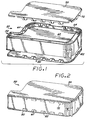
- FIGS. 1 and 2 are isometric views of a TIJ pen having two metal sidecovers attached in accordance with the present invention.
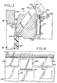
- FIG. 3 illustrates a tool used in the attachment of a metal cover to the TIJ pen of FIG. 1.
- FIG. 4 is a cross-sectional view taken along line 4-4 of FIG. 3.
- FIG. 5 is a cross-sectional view taken along the same line as FIG. 4, but showing the cover press fit into engagement with the dovetail slot features in the frame.
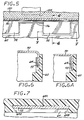
- FIG. 6 is a cross-sectional view taken along line 6-6 of FIG. 5; FIG. 6A is a similar view but of a cover fully seated in the frame.
- FIG. 7 is a cross-sectional view taken along line 7-7 of FIG. 5.
- FIGS. 8 and 9 are closeup views of one exemplary locking tab and frame dovetail slot feature, respectively in positions to be engaged, and in engagement with, each other.
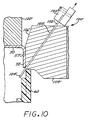
- FIG. 10 illustrates an alternate embodiment of tooling which can be used in the attachment of a metal cover to a TIJ pen.
- FIGS. 11-15 illustrate various configurations of the locking tabs extending from the cover to attach the cover to the TIJ pen.
- FIGS. 1-9 illustrate a TIJ
pen 50 embodying the invention. The pen comprises anexternal frame structure 60, and a pair of side covers 70 and 80. Theframe 60 defines the external periphery of thepen 50 as a narrow, flat structure. The TIJpen 50 provides many benefits for the printing system built to utilize it. Thepen 50 is narrow reducing the required width of the printer carriage and therefore the total printer width. - The
pen 50 includes a simple and efficient ink delivery system, more fully described in the above-reference pending applications, serial nos. 07/928,811 and 07/929,615. Generally, ink is contained within a reservoir formed by two pieces of thinpolyethylene bag material 62 bonded to a compatible plastic material on theframe 60. Two pistons and a spring (not shown) inside the bag provide backpressure to prevent ink from drooling out the printhead 52. - The
frame 60 is made of two different plastic materials. The first material is an engineering plastic forming the external surfaces and providing structural support. An exemplary plastic suitable for the purpose is polyphenyleneoxide (PPO). The second plastic material provides the fluid path for the ink and is suitable for attachment of the bag material, as described more fully in the above-referenced pending application serial number 07/853,372. - The
covers covers covers covers - The metal covers 70 and 80 may be attached to the
plastic frame 60 by adhesives or screw fasteners, or by use of thermal or ultrasonic processes. However, in accordance with another aspect of the invention, the problem of attaching a cover to a thin plastic frame is solved by designing a series of metal tabs on the covers that will lock onto mating plastic features on the frame. The tabs displace plastic on the mating features of the frame during assembly, allowing use of a simple mechanical press to assemble the covers to the frame, with no adhesives, screws, thermal or ultrasonic processes. The design of the cover tabs also enables them to lock into the frame; and the addition of chamfered corners on the tab aids assembly by providing a lead-in surface. The resulting cover/frame seam will resist shear, axial and transverse forces that occur in the joint as a result of externally applied loads to the pen. This joint allows for use of cosmetically suitable cover materials (e.g., pre-painted metal, PVC clad metal, or metals having a suitable cosmetic surface). - The
cover 70 includes a series of spacedtabs 72 which are designed to mate into correspondingdovetailed slot features 64 defined in theframe 60. Thecover 80 is a mirror image of thecover 70, and also includes spacedmetal tabs 82 which are designed to mate into corresponding dovetailed slot features (not shown) in an edge of theframe 60 similar to theslots 64. Because the attachment technique for the two covers 70 and 80 is identical, only the attachment ofcover 70 will be described in detail. - FIG. 2 shows the
cover 70 attached to theframe 60, wherein the cover tabs have been partially press fit into thecorresponding slot features 64 of theframe 60. The only assembly step remaining to the cover-frame configuration of FIG. 2 is to apply force to the cover to fully seat the tabs into the slot features. - The
frames 60 are preferably fabricated by injection molding. Typically the sides of a frame, before integration with the cover, will be bowed slightly inwardly. Similarly, thetabs 72 of atypical cover 70 after fabrication will not be bent exactly perpendicular to the cover surface, but will instead be bent outwardly to a degree. In order to facilitate the mating of the tabs with the slots, special tooling is employed. This tooling acts to force the top edges of the frame sides outwardly to receive the cover, and forces the tabs into a true perpendicular position relative to the cover surface. As a result, the tabs are properly aligned with thedovetailed slots 64 formed in the frame sides, and force can be applied to press fit the tabs into engagement with the slots. Exemplary tooling to accomplish these functions is shown in FIG. 3. - FIG. 3 illustrates a mechanical press arrangement for press fitting the cover tabs into engagement with the slot features 64 of the
frame 60, to result in the partially assembled cover-frame configuration as shown in FIG. 2. Atool 100 includes anarm 102 with anblade tip 104. Adogleg section 106 pivots about pivot point 108. Thearm 102 anddogleg section 106 are connected by apin 105 fixed to thesection 106 and extending through aslot 107 formed in thearm 102. Thearm 102 in turn rides in aslot 103 defined intooling block 109. - A double acting pneumatic cylinder 110 has a
piston rod 112 which is connected to the intermediate area of the dogleg section at point 114. Actuation of the cylinder 110 then causes extension or retraction of thepiston 112, thereby driving thedogleg section 106 to pivot upwardly or downwardly about the pivot point 108, in turn causing thearm 102 to slide upwardly or downwardly withinslot 103. - The
tool 100 further includes aninclined block surface 116 and avertical surface 117 which extends along the side of the cover. As thetabs 72 come into contact with these surfaces, those tabs which are splayed outwardly are bent into a perpendicular position relative to the cover surface. In operation, theblade tip 104 is employed to force the inwardly bowed top edge of the frame outwardly into alignment with the cover tabs. Apress tool 120 is extended downwardly to contact the top surface of thecover 70, pressing the cover downwardly. At the commencement of the operation, theblade tip 104 is fully extended downwardly. Theblade tip 104 is positioned so that it is intermediate twoadjacent tabs 72. As the cover is pressed downwardly, the side of theframe 60 engages theblade tip 104, thereby applying pressure tending to bend the side outwardly as the cover is pressed downwardly. In the meantime, the tabs are aligned by engagement with the block surfaces 116 and 117, tending to align the tabs with the recessed features 64 formed in theframe 60. As thecover 70 continues to be pressed downwardly by thepress tool 120, theblade tip 104 is withdrawn by actuation of the cylinder 110 to lift the blade tip away from engagement with the frame side, until the blade tip is fully retracted away from the side of the frame. This permits thecover 70 to be press fit into engagement with the frame features by continued downward pressure of thepress tool 120. - In this embodiment, the
press tool 120 does not apply sufficient force to fully seat the tabs into theslots 64, but rather only partially seats the tabs to the extent shown in FIG. 2. The partially assembled pen is then moved to another station where another press tool, capable of exerting a greater force, is applied to fully seat the tabs into the dovetailed slots. The press fitting of thetabs 72 into thedovetail slots 64 imparts great rigidity to the installed cover. - It will be understood that typically there will be a plurality of
blade elements 104 for each side of the cover, disposed between adjacent recessed features of the frame, although a blade element is not required for each tab. Thus, there may betools 100 disposed along each side of theframe 60, each with multiple blade tip elements. For eachtool 100, the blade elements will typically be ganged together for actuation by a single cylinder 110. - In one embodiment employing 14 locking tabs around the periphery of the cover, a press force of about 400 pounds is sufficient to properly attach the cover to the frame.
- FIG. 4 shows the position of the
blade end 104 as theblock 120 begins its downward motion. The blade end is disposed between adjacent recessed features 64 formed in theframe 60. - FIG. 5 is a cross-sectional view taken along the same line as FIG. 4, but with the
tabs 72 inserted into thefeatures 64 of theframe 60. FIGS. 6 and 7 illustrate in more detail the manner in which the tabs have been seated into thefeatures 64. FIG. 6 is a cross-section showing the cover which has been partially seated in the frame, as shown in FIGS. 2 and 5. FIG. 6A shows the cover after it has been fully seated, as described above. FIG. 7 shows thebeveled side walls side walls feature 64. Thetab 72 has a width dimension selected so that plastic material comprising theframe 60 must be displaced by the side edges of thetab 72 in order for the tab to fully seat within the slot feature. The beveling of theside walls tab end region 72C has a width dimension which is larger than the width of the tab adjacent thecover 70. The tab tip also has beveled edges which serve to lead the tab into thefeature 64. - FIGS. 8 and 9 illustrate further the manner in which the
tab 72 engages thefeature 64. FIG. 8 shows the relatively wider width dimension of the tab tip than the width of thefeature 64. FIG. 9 shows the tab engaged in the feature, with the side walls displacing plastic material at the edges of thefeature 64. - FIG. 10 illustrates an alternate tool 100' which may be employed to assemble the
cover 70 to thepen frame 60. In this embodiment, theblade 102 has been replaced by a much thinner blade 102' which slidably fits into a narrow groove 103' formed in the tooling block 109'. The blade 102' is formed of a flexible high strength steel, much like the blades of a feeler gauge. The outer end of the blade 102' is connected to a connector block 150, which is connected to a drive element (not shown) which selectively pushes the blade down or pulls it away from the interface between the cover and the frame. In all other respects, the tool 100' operates in the same manner as the tool 100 (FIG. 3). The blade 102' forces the inwardly bowed top edge of the frame to an upright position, while the shoulder 116' forces thetabs 72 to the perpendicular position as shown. - FIGS. 11-15 illustrate various alternative configurations of the
tabs 72. FIGS. 11A and 11B illustrate atab 200 wherein thetap tip 202 is curved with a lead-in radius to facilitate the mating of the tab with the feature formed in the frame. The tip of thetab 200 is reduced in width as well. FIG. 12 shows atab 210 wherein the sides are parallel to each other, and perpendicular to the cover. FIG. 13 shows atab 220 wherein the tab sides initially taper inwardly toward the tip, and taper outwardly to form a pointed bulgedportions tab 230 employing half-circular cutouts tab 240 whereinhook elements - The technique of this invention for attaching a cover to the plastic frame of a TIJ requires a minimum of plastic on the frame yet imparts a high degree of structural integrity to the pen. Another advantage is that the cover may be attached to the frame using a simple mechanical press, and without the use of adhesives, screws, thermal, or ultrasonic processes. The cover tab mating features in the plastic frame can be formed using strong features in the mold consistent with efficiently established parting planes.
- It is understood that the above-described embodiments are merely illustrative of the possible specific embodiments which may represent principles of the present invention. Other arrangements may readily be devised in accordance with these principles by those skilled in the art without departing from the scope and spirit of the invention.
Claims (17)
- An ink-jet pen (50) including an ink reservoir and an ink-jet printhead coupled to said ink reservoir, characterized by:
an external pen frame structure (60) fabricated of a plastic material, said frame structure defining an external periphery of said pen with a first open region; a cover (70) for attachment to said frame structure (60), said cover for covering said open region of said frame; and metal means (72 or 200 or 210 or 220 or 230 or 240) for attaching said cover (70) to said plastic frame structure (60), wherein said cover encloses said open region of said frame structure to protect said ink reservoir. - An ink-jet pen according to Claim 1, further characterized in that said metal means (72) secures only edges of said cover (70) to said frame structure (60) and inhibits flexing of said cover after attachment of said cover to said frame structure, thereby tending to prevent said cover from being deflected and thereby reducing the volume enclosed by said frame structure and said cover and available to said ink reservoir.
- An ink-jet pen according to Claim 1 or Claim 2, further characterized in that said metal attaching means comprises a plurality of metal tabs (72) projecting from the edge of said cover (70) and a corresponding plurality of tab receptacles (64) formed in said plastic frame (60), said tabs being received in said receptacles to form a tab-to-receptacle connection.
- An ink-jet pen according to Claim 1 or Claim 2, further characterized by a plurality of tab mating features (64) formed in said frame structure (60) adjacent said open region and in that said metal means comprises a plurality of spaced metal tabs (72) projecting from a surface of said cover (70), wherein said tabs of said cover are press fit into engagement with corresponding mating features (64) formed adjacent said open region such that said tabs displace plastic on said mating features, and thereby secure said cover to said frame structure.
- An ink-jet pen according to Claim 4, further characterized in that said respective tabs (72) include an end portion (72C) which is enlarged with respect to the body of said tab, said end portion displacing plastic on said respective mating features (64).
- An ink-pen according to Claim 5, further characterized in that said tab end portion (72C) further includes chamfered corners to assist in engagement of said tabs (72) with said mating features (64).
- An ink-jet pen according to any of Claims 4, 5 or 6, further characterized in that said mating features comprise a slot (64) formed in said frame (60), said slot having a width dimension smaller than a corresponding width dimension of said tab, wherein as said tab (72) is press fit into said slot, plastic surrounding said slot is displaced.
- An ink-jet pen according to Claim 7, further characterized in that said slot (64) further includes beveled sides (64A, 64B) presenting plastic material at said sides which is displaced as said tab (72) is press fit into said slot.
- An ink-jet pen according to any of Claims 4, 5 or 6, further characterized in that said tabs (200) comprise a tab tip (202) curved inwardly to define a lead-in radius to facilitate engagement of said tabs with said mating features (64) of said frame structure (60).
- An ink-jet pen according to any of Claims 4, 5 or 6, further characterized in that said tabs (220) taper initially taper inwardly toward the tip thereof, and then taper outwardly to form pointed bulged portions (222, 224) adjacent each tab side.
- An ink-jet pen according to any of Claims 4, 5 or 6, further characterized in that said tabs (230) define half-circular cutouts (232, 234) adjacent the tab tip.
- An ink-jet pen according to any of Claims 4, 5 or 6, further characterized in that said tabs (240) comprise hook elements (242, 244) defined in each tab side to engage said frame feature.
- An ink-jet pen according to Claim 4 or Claim 5, further characterized in that said frame structure comprises a peripheral upright pen side member, and wherein said mating features comprise a plurality of slots (64) defined in said upright side member and extending along said side member.
- An ink-jet pen according to any preceding claim, further characterized in that said frame structure (60) defines a second open region, such that said first and second open regions are opposed side open regions, and further comprising a second cover (80) for attachment to said frame structure, said second cover for covering said second open region, and metal means (82) for attaching said second cover to said plastic frame structure (60), wherein said covers enclose said open regions of said frame structure to protect said ink reservoir.
- A method for attaching a cover (70) to an ink-jet pen (50), characterized by the following steps:
providing an external pen frame structure (60) fabricated of a plastic material, said frame structure comprising a plurality of tab mating features (64); aligning a cover (70) with said frame structure (60), said cover having a plurality of spaced metal tabs projecting from a surface thereof for engagement with mating features (64) of said frame structure; and forcing said cover (70) and frame structure (60) together to press fit said tabs (72) into engagement with said mating features (64) of said frame structure such that said tabs displace plastic on said mating features, wherein said tabs become locked into said frame features, and thereby secure said cover onto said frame structure. - A method according to Claim 15, wherein said step of aligning said cover (70) with said frame structure (60) include positioning said cover between blade members (104) at areas between adjacent tabs (72) so that said cover is positioned just above said frame structure with said tabs aligned with corresponding frame features.
- A method according to Claim 15 or Claim 16, wherein said step of forcing said cover (70) and said frame structure (60) together includes deploying a pressing tool (120) to press said cover into engagement with said frame structure.
Applications Claiming Priority (2)
| Application Number | Priority Date | Filing Date | Title |
|---|---|---|---|
| US07/994,810 US5610644A (en) | 1992-12-22 | 1992-12-22 | Thermal ink-jet pen with a plastic/metal attachment for the cover |
| US994810 | 1992-12-22 |
Publications (3)
| Publication Number | Publication Date |
|---|---|
| EP0603473A2 true EP0603473A2 (en) | 1994-06-29 |
| EP0603473A3 EP0603473A3 (en) | 1997-10-15 |
| EP0603473B1 EP0603473B1 (en) | 1999-12-08 |
Family
ID=25541081
Family Applications (1)
| Application Number | Title | Priority Date | Filing Date |
|---|---|---|---|
| EP93114942A Expired - Lifetime EP0603473B1 (en) | 1992-12-22 | 1993-09-16 | Thermal ink-jet pen with a plastic/metal attachment for the cover |
Country Status (4)
| Country | Link |
|---|---|
| US (1) | US5610644A (en) |
| EP (1) | EP0603473B1 (en) |
| JP (1) | JP3670675B2 (en) |
| DE (1) | DE69327225T2 (en) |
Families Citing this family (6)
| Publication number | Priority date | Publication date | Assignee | Title |
|---|---|---|---|---|
| US6003984A (en) * | 1992-03-18 | 1999-12-21 | Hewlett-Packard Co. | Ink-jet swath printer with auxiliary ink reservoir |
| KR0144890B1 (en) * | 1995-05-27 | 1998-07-15 | 김광호 | Caption/teletext broadcasting indicator apparatus and method of double screen tv |
| US6183072B1 (en) | 1998-04-29 | 2001-02-06 | Hewlett-Packard Company | Seal using gasket compressed normal to assembly axis of two parts |
| US6527378B2 (en) | 2001-04-20 | 2003-03-04 | Hewlett-Packard Company | Thermal ink jet defect tolerant resistor design |
| US6595479B2 (en) * | 2001-05-15 | 2003-07-22 | Hubbell Incorporated | Electrical fixture mounting assembly |
| US7992961B2 (en) * | 2006-03-31 | 2011-08-09 | Brother Kogyo Kabushiki Kaisha | Ink-jet head |
Citations (4)
| Publication number | Priority date | Publication date | Assignee | Title |
|---|---|---|---|---|
| US4616764A (en) * | 1984-11-30 | 1986-10-14 | Kabushiki Kaisha Toshiba | Case having snap-on cover |
| EP0378241A2 (en) * | 1989-01-13 | 1990-07-18 | Canon Kabushiki Kaisha | Storage container |
| US5138344A (en) * | 1990-02-02 | 1992-08-11 | Canon Kabushiki Kaisha | Ink jet apparatus and ink jet cartridge therefor |
| EP0516088A2 (en) * | 1991-05-27 | 1992-12-02 | Seiko Epson Corporation | Ink cartridge for ink jet recording apparatus |
Family Cites Families (5)
| Publication number | Priority date | Publication date | Assignee | Title |
|---|---|---|---|---|
| US3913774A (en) * | 1973-03-12 | 1975-10-21 | Leslie Vajtay | End caps for containers |
| US4739339A (en) * | 1986-02-14 | 1988-04-19 | Dataproducts Corporation | Cartridge and method of using a cartridge for phase change ink in an ink jet apparatus |
| US4931811A (en) * | 1989-01-31 | 1990-06-05 | Hewlett-Packard Company | Thermal ink jet pen having a feedtube with improved sizing and operational with a minimum of depriming |
| US5464578A (en) * | 1992-03-18 | 1995-11-07 | Hewlett-Packard Company | Method of making a compact fluid coupler for thermal inkjet print cartridge ink reservoir |
| US5451995A (en) * | 1992-12-22 | 1995-09-19 | Hewlett-Packard Company | Rigid loop case structure for thermal ink-jet pen |
-
1992
- 1992-12-22 US US07/994,810 patent/US5610644A/en not_active Expired - Lifetime
-
1993
- 1993-09-16 DE DE69327225T patent/DE69327225T2/en not_active Expired - Lifetime
- 1993-09-16 EP EP93114942A patent/EP0603473B1/en not_active Expired - Lifetime
- 1993-12-22 JP JP34617293A patent/JP3670675B2/en not_active Expired - Lifetime
Patent Citations (4)
| Publication number | Priority date | Publication date | Assignee | Title |
|---|---|---|---|---|
| US4616764A (en) * | 1984-11-30 | 1986-10-14 | Kabushiki Kaisha Toshiba | Case having snap-on cover |
| EP0378241A2 (en) * | 1989-01-13 | 1990-07-18 | Canon Kabushiki Kaisha | Storage container |
| US5138344A (en) * | 1990-02-02 | 1992-08-11 | Canon Kabushiki Kaisha | Ink jet apparatus and ink jet cartridge therefor |
| EP0516088A2 (en) * | 1991-05-27 | 1992-12-02 | Seiko Epson Corporation | Ink cartridge for ink jet recording apparatus |
Also Published As
| Publication number | Publication date |
|---|---|
| JPH06255095A (en) | 1994-09-13 |
| DE69327225T2 (en) | 2000-07-13 |
| DE69327225D1 (en) | 2000-01-13 |
| EP0603473A3 (en) | 1997-10-15 |
| US5610644A (en) | 1997-03-11 |
| JP3670675B2 (en) | 2005-07-13 |
| EP0603473B1 (en) | 1999-12-08 |
Similar Documents
| Publication | Publication Date | Title |
|---|---|---|
| US6390593B1 (en) | Foam-filled caps for sealing inkjet printheads | |
| US7357495B2 (en) | Liquid container with internal liquid pack | |
| CA1216464A (en) | Screen printing frame | |
| US5517219A (en) | Ink jet recording apparatus having an improved capping mechanism | |
| DE60011848T2 (en) | Ink tank, valve unit, ink tank manufacturing method, ink jet cartridge and recording apparatus | |
| EP0591844B1 (en) | A recovery mechanism and an ink jet recording apparatus with said recovery mechanism | |
| US5610644A (en) | Thermal ink-jet pen with a plastic/metal attachment for the cover | |
| EP0585615A2 (en) | Liquid storing container for recording apparatus | |
| DE20122653U1 (en) | Ink cartridge and ink jet recording device using the same | |
| DE112005001041T5 (en) | Ink tank, printhead and inkjet printer | |
| CN1090098C (en) | Method and device for ink container locking | |
| JP4150461B2 (en) | Seal using a gasket that is compressed perpendicular to the assembly axis of the two parts | |
| EP1219445B1 (en) | Ink cartridge | |
| US7360879B2 (en) | Inkjet pen adapter | |
| US6435675B2 (en) | Method for manufacturing ink tank, ink tank, ink jet cartridge, and ink jet recording apparatus | |
| JPH04187448A (en) | Ink cartridge | |
| CN214519709U (en) | Stylus positioning and pressure maintaining tool | |
| EP0451846B1 (en) | Cap member for a recovery device and suction recovery method | |
| JP3988257B2 (en) | Image forming apparatus and cartridge member | |
| US7703881B2 (en) | Print head cleaning member | |
| JP3417414B2 (en) | Pump drive method for inkjet printer | |
| JP4266881B2 (en) | Recording device | |
| US7762794B2 (en) | Tube and tube pump | |
| JP3006958B2 (en) | Ink jet recording device and recording head | |
| JP2962873B2 (en) | Ink jet recording device |
Legal Events
| Date | Code | Title | Description |
|---|---|---|---|
| PUAI | Public reference made under article 153(3) epc to a published international application that has entered the european phase |
Free format text: ORIGINAL CODE: 0009012 |
|
| AK | Designated contracting states |
Kind code of ref document: A2 Designated state(s): DE FR GB IT |
|
| PUAL | Search report despatched |
Free format text: ORIGINAL CODE: 0009013 |
|
| AK | Designated contracting states |
Kind code of ref document: A3 Designated state(s): DE FR GB IT |
|
| 17P | Request for examination filed |
Effective date: 19980316 |
|
| GRAG | Despatch of communication of intention to grant |
Free format text: ORIGINAL CODE: EPIDOS AGRA |
|
| GRAG | Despatch of communication of intention to grant |
Free format text: ORIGINAL CODE: EPIDOS AGRA |
|
| GRAH | Despatch of communication of intention to grant a patent |
Free format text: ORIGINAL CODE: EPIDOS IGRA |
|
| 17Q | First examination report despatched |
Effective date: 19990129 |
|
| GRAH | Despatch of communication of intention to grant a patent |
Free format text: ORIGINAL CODE: EPIDOS IGRA |
|
| GRAA | (expected) grant |
Free format text: ORIGINAL CODE: 0009210 |
|
| AK | Designated contracting states |
Kind code of ref document: B1 Designated state(s): DE FR GB IT |
|
| PG25 | Lapsed in a contracting state [announced via postgrant information from national office to epo] |
Ref country code: IT Free format text: LAPSE BECAUSE OF FAILURE TO SUBMIT A TRANSLATION OF THE DESCRIPTION OR TO PAY THE FEE WITHIN THE PRE;WARNING: LAPSES OF ITALIAN PATENTS WITH EFFECTIVE DATE BEFORE 2007 MAY HAVE OCCURRED AT ANY TIME BEFORE 2007. THE CORRECT EFFECTIVE DATE MAY BE DIFFERENT FROM THE ONE RECORDED.SCRIBED TIME-LIMIT Effective date: 19991208 Ref country code: FR Free format text: LAPSE BECAUSE OF FAILURE TO SUBMIT A TRANSLATION OF THE DESCRIPTION OR TO PAY THE FEE WITHIN THE PRESCRIBED TIME-LIMIT Effective date: 19991208 |
|
| REF | Corresponds to: |
Ref document number: 69327225 Country of ref document: DE Date of ref document: 20000113 |
|
| EN | Fr: translation not filed | ||
| PLBE | No opposition filed within time limit |
Free format text: ORIGINAL CODE: 0009261 |
|
| STAA | Information on the status of an ep patent application or granted ep patent |
Free format text: STATUS: NO OPPOSITION FILED WITHIN TIME LIMIT |
|
| 26N | No opposition filed | ||
| REG | Reference to a national code |
Ref country code: GB Ref legal event code: 732E |
|
| REG | Reference to a national code |
Ref country code: GB Ref legal event code: IF02 |
|
| REG | Reference to a national code |
Ref country code: GB Ref legal event code: 732E Free format text: REGISTERED BETWEEN 20120329 AND 20120404 |
|
| PGFP | Annual fee paid to national office [announced via postgrant information from national office to epo] |
Ref country code: GB Payment date: 20120925 Year of fee payment: 20 |
|
| PGFP | Annual fee paid to national office [announced via postgrant information from national office to epo] |
Ref country code: DE Payment date: 20120927 Year of fee payment: 20 |
|
| REG | Reference to a national code |
Ref country code: DE Ref legal event code: R071 Ref document number: 69327225 Country of ref document: DE |
|
| REG | Reference to a national code |
Ref country code: GB Ref legal event code: PE20 Expiry date: 20130915 |
|
| PG25 | Lapsed in a contracting state [announced via postgrant information from national office to epo] |
Ref country code: DE Free format text: LAPSE BECAUSE OF EXPIRATION OF PROTECTION Effective date: 20130917 |
|
| PG25 | Lapsed in a contracting state [announced via postgrant information from national office to epo] |
Ref country code: GB Free format text: LAPSE BECAUSE OF EXPIRATION OF PROTECTION Effective date: 20130915 |