EP0602944A2 - Process for impregnation and expansion of tobacco - Google Patents
Process for impregnation and expansion of tobacco Download PDFInfo
- Publication number
- EP0602944A2 EP0602944A2 EP93310103A EP93310103A EP0602944A2 EP 0602944 A2 EP0602944 A2 EP 0602944A2 EP 93310103 A EP93310103 A EP 93310103A EP 93310103 A EP93310103 A EP 93310103A EP 0602944 A2 EP0602944 A2 EP 0602944A2
- Authority
- EP
- European Patent Office
- Prior art keywords
- tobacco
- carbon dioxide
- pressure
- impregnation
- vessel
- Prior art date
- Legal status (The legal status is an assumption and is not a legal conclusion. Google has not performed a legal analysis and makes no representation as to the accuracy of the status listed.)
- Granted
Links
Images


Classifications
-
- A—HUMAN NECESSITIES
- A24—TOBACCO; CIGARS; CIGARETTES; SIMULATED SMOKING DEVICES; SMOKERS' REQUISITES
- A24B—MANUFACTURE OR PREPARATION OF TOBACCO FOR SMOKING OR CHEWING; TOBACCO; SNUFF
- A24B3/00—Preparing tobacco in the factory
-
- A—HUMAN NECESSITIES
- A24—TOBACCO; CIGARS; CIGARETTES; SIMULATED SMOKING DEVICES; SMOKERS' REQUISITES
- A24B—MANUFACTURE OR PREPARATION OF TOBACCO FOR SMOKING OR CHEWING; TOBACCO; SNUFF
- A24B3/00—Preparing tobacco in the factory
- A24B3/18—Other treatment of leaves, e.g. puffing, crimpling, cleaning
- A24B3/182—Puffing
Definitions
- This invention relates to a process for expanding the volume of tobacco. More particularly this invention relates to expanding tobacco using carbon dioxide.
- the tobacco art has long recognized the desirability of expanding tobacco to increase the bulk or volume of tobacco. There have been various reasons for expanding tobacco.
- One of the early purposes for expanding tobacco involved making up the loss of weight caused by the tobacco curing process.
- Another purpose was to improve the smoking characteristics of particular tobacco components, such as tobacco stems.
- U.S. Patent No. 1,789,435 describes a method and apparatus for expanding the volume of tobacco in order to make up the loss of volume caused in curing tobacco leaf.
- a gas which may be air, carbon dioxide or steam under pressure and the pressure is then relieved, the tobacco tends to expand.
- the patent states that the volume of the tobacco may, by that process, be increased to the extent of about 5-15%.
- U.S. Patent No. 3,771,533, commonly assigned herewith involves a treatment of tobacco with carbon dioxide and ammonia gases, whereby the tobacco is saturated with these gases and ammonium carbamate is formed in situ.
- the ammonium carbamate is thereafter decomposed by heat to release the gases within the tobacco cells and to cause expansion of the tobacco.
- U.S. Patent No. 4,258,729 commonly assigned herewith, describes a method for expanding the volume of tobacco in which the tobacco is impregnated with gaseous carbon dioxide under conditions such that the carbon dioxide remains substantially in the gaseous state. Pre-cooling the tobacco prior to the impregnation step or cooling the tobacco bed by external means during impregnation is limited to avoid condensing the carbon dioxide to any significant degree.
- U.S. Patent No. 4,235,250 commonly assigned herewith, describes a method for expanding the volume of tobacco in which the tobacco is impregnated with gaseous carbon dioxide under conditions such that the carbon dioxide remains substantially in the gaseous state. During depressurization some of the carbon dioxide is converted to a partially condensed state within the tobacco. That patent teaches that the carbon dioxide enthalpy is controlled in such a manner to minimize carbon dioxide condensation.
- U.S. Patent No. RE. 32,013 commonly assigned herewith, describes a method and apparatus for expanding the volume of tobacco in which the tobacco is impregnated with liquid carbon dioxide, converting the liquid carbon dioxide or solid carbon dioxide in situ, and then causing the solid carbon dioxide to vaporize and expand the tobacco.
- a loosely filled tobacco bed exhibits a tobacco bulk density gradient with a higher bulk density toward the bottom due to the compressing effect of the weight of the column of tobacco.
- Tobacco expansion processes using gaseous carbon dioxide and loosely filled tobacco beds of relatively low bulk density may result in non-uniform cooling of the tobacco and thus non-uniform stability and expansion of the tobacco.
- the bulk density at the bottom of a deep tobacco bed may be the limiting factor in a gas-only process, because the tobacco at the bottom of a deep bed may have too great a bulk density to be efficiently cooled by gas expansion cooling.
- tobacco expansion processes using yaseous carbon dioxide are limited to relatively small or shallow tobacco beds. While such small beds have been used for experimental development, they were not usually commercially practical.
- the compaction may be effected by straightforward compression of a batch of tobacco or by processing steps such as cutting.
- the tobacco is initially compacted to a bulk density not less than 10lb/cu.ft. (160.2 kg/m3) .
- the bulk density preferably does not exceed 20lb/cu.ft. (320.4 kg/m3) bulk densities of 12 to 16 lb/cu.ft. (192.2 to 256.3 kg/m3), preferably 13 to 15 lb/cu.ft. (208.2 to 240.3 kg/m3), are advantageous.
- the compacted tobacco is cooled before it is impregnated with CO2 under pressure. This cooling may be effected by flowing CO2 gas through the tobacco.
- the CO2 gas is at or near saturation and when it contacts the tobacco sufficient of the CO2 is condensed on the tobacco to ensure that when the pressure is subsequently released expansion of the carbon dioxide gas and evaporation of the condensed carbon dioxide lower the temperature of the impregnated tobacco to a temperature in the range -35° to 20°F (-37.4° to -6.7°C).
- the impregnated tobacco is expanded in conventional manner, for example by heating at atmospheric pressure.
- Tobacco impregnated according to the present invention may be expanded using less energy, e.g., a significantly lower temperature gas stream may be used at a comparable residence time, than tobacco impregnated under conditions where liquid carbon dioxide is used.
- the present invention affords greater control of the chemical and flavor components, e.g., reducing sugars and alkaloids, in the final tobacco product by allowing expansion to be carried out over a greater temperature range than was practical in the past.
- chemical and flavor components e.g., reducing sugars and alkaloids
- impregnating and expanding tobacco can achieve a greater process throughput than processes using gaseous carbon dioxide under conditions that do not result in condensation of the carbon dioxide prior to venting.
- evaporation of condensed carbon dioxide provides sufficient cooling so that even tobacco of a substantially high bulk density may be effectively impregnated and expanded. This evaporation cooling is preferable in high bulk density tobacco beds for achieving a sufficiently low post-vent tobacco temperature to ensure stability of the impregnated tobacco.
- the post-vent tobacco temperature is essentially independent of tobacco bulk density.
- the invention is applicable to both large and small batch operation.
- the compression or compaction of the tobacco before impregnation not only results in a desirably high bulk density but also gives a more uniform density throughout the bed. Thereby, in addition to further ensuring uniformity of carbon dioxide impregnation, the mass throughput of the process may be increased.
- the process throughput may also be increased by loading the impregnator to higher tobacco bulk densities in accordance with one of the preferred embodiments of the present invention.
- the compacted tobacco bed is less likely than a loose tobacco bed to settle due to gravity or gas flow which may otherwise create an undesirable void space in the impregnator.
- less heat of compression develops because a smaller volume of gas is compressed per pound of tobacco.
- the condensed carbon dioxide on the tobacco at the latter stages of pressurization avoids the localization of heat of compression. Because of the sufficiently low post-vent temperatures achieved, the process of the invention achieves acceptable carbon dioxide retention and stability after impregnation even with a high bulk density of tobacco.
- the reduced quantity of carbon dioxide gas required with elevated bulk densities also achieves environmental benefits, because less gas is vented to the atmosphere per pound of tobacco.
- the present invention relates broadly to a process for expanding tobacco employing a readily available, relatively inexpensive, non-combustible and non-toxic expansion agent. More particularly, the present invention relates to the production of an expanded tobacco product of substantially reduced density and increased filling power, produced by impregnating tobacco under pressure with saturated gaseous carbon dioxide and a controlled amount of condensed liquid carbon dioxide, rapidly releasing the pressure, and then causing the tobacco to expand. Expansion may be accomplished by subjecting the impregnated tobacco to heat, radiant energy or similar energy generating conditions which will cause the carbon dioxide impregnant to rapidly expand.
- the tobacco to be impregnated preferably has a particle size of from about 6 mesh to about 100 mesh, more preferably the tobacco has a particle size not less than about 30 mesh.
- mesh refers to United States standard sieve and those values reflect the ability of more than 95% of the particles of a given size to pass through a screen of a given mesh value.
- % moisture may be considered equivalent to oven-volatiles content (OV) since not more than about 0.9% of tobacco weight is volatiles other than water.
- Oven volatiles determination is a simple measurement of tobacco weight loss after exposure for 3 hours in a circulating air oven controlled at 212°F (100°C) . The weight loss as percentage of initial weight is oven-volatiles content.
- the tobacco to be treated will have an OV content of at least about 12% and less than about 21%.
- the tobacco to be treated will have an OV content of about 13% to about 16%.
- Below about 12% OV tobacco is too easily broken, resulting in a large amount of tobacco fines.
- Above about 21% OV excessive amounts of pre-cooling are needed to achieve acceptable stability and a very low post-vent temperature is required, resulting in a brittle tobacco which is easily broken.
- the tobacco in order to achieve a desirable high bulk density or a more uniform density throughout the tobacco bed, or both a high bulk density and a more uniform tobacco bed, the tobacco is compacted or compressed before it is impregnated with carbon dioxide.
- the tobacco may be compacted before it is placed in the pressure vessel, within the pressure vessel or both, so that the resultant bulk density of the tobacco in the pressure vessel is essentially uniform and substantially greater than the bulk density of a typical loose fill tobacco.
- the tobacco-containing pressure vessel is preferably purged with carbon dioxide gas, the purging operation generally taking from about 1 minute to about 4 minutes.
- purge requirements may be reduced because void space may be minimized and because the vessel may be smaller per pound of tobacco.
- the example described in detail below with reference to Figures 14-16 operates with only a 5 second purge step.
- the purging step may be eliminated without detriment to the final product.
- the benefits of purging are the removal of gases that may interfere with carbon dioxide recovery and the removal of foreign gases that may interfere with full penetration of the carbon dioxide.
- the gaseous carbon dioxide which is employed in the process of this invention will generally be obtained from a supply tank where it is maintained in saturated liquid form at a pressure of from about 400 psig to about 1050 psig (2758 kPa to 7239 kPa).
- the supply tank may be fed with recompressed gaseous carbon dioxide vented from the pressure vessel.
- Additional carbon dioxide may be obtained from a storage vessel where it is maintained in liquid form generally at a pressure of from about 215 psig to about 305 psig (1482 kPa to 2103 kPa) and temperatures of from about -20°F to about 0°F (-28.9°C to -17.8°C).
- liquid carbon dioxide from the storage vessel may be mixed with the recompressed gaseous carbon dioxide and stored in the supply tank.
- liquid carbon dioxide from the storage vessel may be preheated, for example, by suitable heating coils around the feed line, to a temperature of about 0°F to about 84°F (-17.8°C to 29°C) and a pressure of about 300 psig to about 1000 psig (2068 kPa to 6894 kPa) before being introduced into the pressure vessel.
- the interior of the vessel including the tobacco to be treated, will generally be at a temperature of from about 20°F to about 80°F (-6.7°C to 26.7°C) and a pressure sufficient to maintain the carbon dioxide gas at or substantially at a saturated state.
- Tobacco stability i.e. the length of time the impregnated tobacco may be stored after depressurisation before the final expansion step and still be satisfactorily expanded, is dependent on the initial tobacco OV content, i.e., pre-impregnation OV content, and the tobacco temperature after venting of the pressure vessel.
- Tobacco with a higher initial OV content requires a lower tobacco post-vent temperature than tobacco with a lower initial OV content to achieve the same degree of stability.
- the effect of OV content on the stability of tobacco impregnated with carbon dioxide gas at 250 psia (1723.5 kPa) and -18°C was determined by placing a weighed sample of bright tobacco, typically about 60g to about 70g, in a 300 cc pressure vessel. The vessel was then immersed in a temperature controlled bath set at -18°C. After the vessel reached thermal equilibrium with the bath, the vessel was purged with carbon dioxide gas. The vessel was then pressured to about 250 psia (1723.5 kPa). Gas phase impregnation was assured by maintaining the carbon dioxide pressure at least 20 psi to 30 psi (1379 kPa to 2068 kPa) below the carbon dioxide saturation pressure at -18°C.
- the vessel pressure was rapidly decreased to atmospheric pressure in about 3 seconds to about 4 seconds by venting to atmosphere.
- the vent valve was immediately closed and the tobacco remained in the pressure vessel immersed in the temperature controlled bath at -18°C for about 1 hour.
- the vessel temperature was increased to about 25°C over about two hours in order to liberate the carbon dioxide remaining in the tobacco.
- the vessel pressure and temperature were continually monitored using an IBM compatible computer with LABTECH version 4 data acquisition software from Laboratories Technologies Corp. The amount of carbon dioxide evolved by the tobacco over time at a constant temperature, can be calculated based on the vessel pressure over time.
- Figure 3 compares the stability of about 12%, 14%, 16.2% and 20% OV bright tobacco impregnated with carbon dioxide gas at 250 psia (1723.5 kPa) at -18°C as described above. Tobacco with an OV content of about 20% lost about 71% of its carbon dioxide pickup after 15 minutes at -18°C, while tobacco with an OV content of about 12% lost only about 25% of its carbon dioxide pickup after 60 minutes. The total amount of carbon dioxide evolved after increasing the vessel temperature to 25°C is an indication of the total carbon dioxide pickup. This data indicates that, for impregnations at comparable pressures and temperatures, as tobacco OV content increases, tobacco stability decreases.
- the tobacco temperature be approximately about 0°F to about 10°F (-17.8°C to -12.2°C) after venting of the pressure vessel when the tobacco to be expanded has an initial OV content of about 15%.
- Tobacco with an initial OV content greater than about 15% should have a post-vent temperature lower than about 0°F to about 10°F (-17.8°C to -12.2°C) and tobacco with an initial OV content less than 15% may be maintained at a temperature greater than about 0°F to about 10°F (-17.8°C to -12.2°C) in order to achieve a comparable degree of stability.
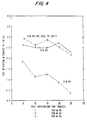
- Figure 4 illustrates the effect of tobacco post-vent temperature on tobacco stability at various OV contents.
- Figure 4 shows that tobacco with a higher OV content, about 21%, requires a lower post-vent temperature, about -35°F (-37.4°C), in order to achieve a similar level of carbon dioxide retention over time as compared to a tobacco with a lower OV content, about 12%, with a post-vent temperature of about 0°F to about 10°F (-17.8°C to -12.2°C).
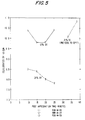
- Figures 5 and 6, respectively, show the effect of tobacco OV content and post-vent temperature on equilibrated CV and specific volume of tobacco expanded after being held at its indicated post-vent temperature for the indicated time.
- Figures 4, 5 and 6 are based on data from Runs 49, 54 and 65.
- bright tobacco was placed in a pressure vessel with a total volume of 3.4 cubic feet (.096m3), 2.4 cubic feet (.068m3) of which was occupied by the tobacco.
- Runs 54 and 65 approximately 22 lbs. (9.97 kg) of 20% OV tobacco was placed in the pressure vessel.
- This tobacco was pre-cooled by flowing carbon dioxide gas through the vessel at about 421 psig (2902 kPa) and at about 153 psig (1055 kPa) for Runs 54 and 65, respectively, for about 4 to 5 minutes prior to pressurization to about 800 psig (5515 kPa) with carbon dioxide gas.
- Impregnation pressure, mass ratio of carbon dioxide to tobacco, and heat capacity of tobacco can be manipulated in such a manner that under specific circumstances, the amount of cooling required from the evaporation of condensed carbon dioxide is small relative to the cooling provided by the expansion of carbon dioxide gas upon depressurization.
- the mass ratio of carbon dioxide gas to tobacco decreases, i.e., as the tobacco bulk density increases, the cooling required from the evaporation of condensed carbon dioxide increases.
- cylinder volume is a unit for measuring the degree of expansion of tobacco. As used throughout this application, the values employed, in connection with these terms are determined as follows:
- Tobacco filler weighing 20 grams, if unexpanded, or 10 grams, if expanded, is placed in a 6-cm diameter Densimeter cylinder, Model No. DD-60, designed by the Heinr. Borgwaldt Company, Heinr. Borgwaldt GmbH, Schnackenburgallee No. 15, Postfack 54 07 02, 2000 Hamburg 54 West Germany.
- a 2 kg piston, 5.6 cm in diameter is placed on the tobacco in the cylinder for 30 seconds.
- the resulting volume of the compressed tobacco is read and divided by the tobacco sample weight to yield the cylinder volume as cc/gram.
- the test determines the apparent volume of a given weight of tobacco filler.
- the resulting volume of filler is reported as cylinder volume. This test is carried out at standard environmental conditions of 75°F (24°C) and 60% RH; conventionally, unless otherwise stated, the sample is preconditioned in this environment for 24-48 hours.
- the term "specific volume” is a unit for measuring the volume and true density of solid objects, e.g., tobacco, using the fundamental principles of the ideal gas law.
- the specific volume is determined by taking the inverse of the density and is expressed as "cc/g".
- a weighed sample of tobacco, either "as is”, dried at 100°C for 3 hours, or equilibrated, is placed in a cell in a Quantachrome Penta-Pycnometer. The cell is then purged and pressured with helium. The volume of helium displaced by the tobacco is compared with volume of helium required to fill an empty sample cell and the tobacco volume is determined based on Archimedes' principle.
- specific volume was determined using the same tobacco sample used to determine OV, i.e., tobacco dried after exposure for 3 hours in a circulating air oven controlled at 100°C.
- the degree of tobacco stability required is dependent on many factors including the length of time after depressurization and before expansion of the tobacco. Therefore, the selection of a desired post-vent temperature should be made in light of the degree of stability required.
- the impregnated tobacco is handled between the impregnation and expansion steps so as to maintain the tobacco's retention of carbon dioxide.
- the tobacco should be conveyed by an insulated and cooled conveyor, and should be isolated from any moisture laden air.
- the desired tobacco post-vent temperature may be obtained by any suitable means including pre-cooling of the tobacco before introducing it to the pressure vessel, in-situ cooling of the tobacco in the pressure vessel by purging with cold carbon dioxide or other suitable means, or vacuum cooling in situ augmented by flow through of carbon dioxide gas.
- Vacuum cooling has the advantage of reducing the tobacco OV content without thermal degradation of the tobacco. Vacuum cooling also removes non-condensible gases from the vessel, thereby allowing the purging step to be eliminated. Vacuum cooling can be effectively and practically used to reduce the tobacco temperature to as low as about 30°F (-1°C). It is preferred that the tobacco is cooled in situ in the pressure vessel.
- the amount of pre-cooling or in-situ cooling required to achieve the desired tobacco post-vent temperature is dependent on the amount of cooling provided by the expansion of the carbon dioxide gas during depressurization.
- the amount of tobacco cooling due to the expansion of the carbon dioxide gas is a function of the ratio of the mass of the carbon dioxide gas to the mass of tobacco, the heat capacity of the tobacco, the final impregnation pressure, and the system temperature. Therefore, for a given impregnation, when the tobacco feed and the system pressure, temperature and volume are fixed, control of the final post-vent temperature of the tobacco may be achieved by controlling the amount of carbon dioxide permitted to condense on the tobacco.
- the amount of tobacco cooling due to evaporation of the condensed carbon dioxide from the tobacco is a function of the ratio of the mass of condensed carbon dioxide to the mass of tobacco, the heat capacity of the tobacco, and the temperature or pressure of the system.
- the required tobacco stability is determined by the specific design of the impregnation and expansion processes used.
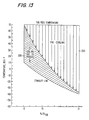
- Figure 13 illustrates the tobacco post-vent temperature required to achieve the desired tobacco stability as a function of OV for a particular process design.
- the lower shaded area 200 illustrates the amount of cooling contributed by carbon dioxide gas expansion and the upper area 250 illustrates the amount of additional cooling required by carbon dioxide liquid evaporation as a function of tobacco OV to provide the required stability.
- adequate tobacco stability is achieved when the tobacco temperature is at or below the temperature shown by the "stability" line.
- the process variables which determine the tobacco post-vent temperature include the variables discussed previously and other variables including, but not limited to, vessel temperature, vessel mass, vessel volume, vessel configuration, flow geometry, equipment orientation, heat transfer rate to the vessel walls, and process designed retention time between impregnation and expansion.
- This higher tobacco post-vent temperature and lower tobacco OV allow the expansion step to be conducted at a significantly lower temperature, resulting in an expanded tobacco with less toasting and less loss of flavor.
- less energy is required to expand the tobacco. moreover, because very little, if any, solid carbon dioxide is formed, handling of the impregnated tobacco is simplified.
- tobacco impregnated according to the present invention does not tend to form clumps which must be mechanically broken. Thus, a greater usable-tobacco yield is achieved because the clump-breaking step which results in tobacco fines too small for use in cigarettes is eliminated.
- OV tobacco at about -35°F (-37.4°C) to about 12% OV tobacco at about 20°F (-6.7°C), unlike any OV tobacco at about -110°F (-79°C), is not brittle and, therefore, is handled with minimum degradation. This property results in a greater yield of usable tobacco because less tobacco is mechanically broken during normal handling, e.g., during unloading of the pressure vessel or transfer from the pressure vessel to the expansion zone.
- Chemical changes during expansion of the impregnated tobacco can be reduced by increasing the exit tobacco OV, i.e. the tobacco OV content immediately after expansion, to about 6% OV or higher. This can be accomplished by reducing the temperature of the expansion step.
- an increase in tobacco exit OV is coupled with a decrease in the amount of expansion achieved.
- the decrease in the amount of expansion depends strongly on the starting feed OV content of the tobacco. As the tobacco feed OV is reduced to approximately 13%, minimal reduction in the degree of expansion is observed even at a tobacco moisture content of about 6% or more exiting the expansion device. Therefore, if the feed OV and the expansion temperature are reduced, surprisingly good expansion can be attained while chemical changes are minimized. This is shown in Figures 7, 8 and 9.
- Figures 7, 8 and 9 are based on data from Runs 2241 through 2242 and 2244 through 2254. This data is tabulated in Table 2. In each of these runs a measured amount of bright tobacco was placed in a pressure vessel similar to the vessel described in Example 1.
- Liquid carbon dioxide at 430 psig (2964 kPa) was used to impregnate the tobacco in Runs 2241 and 2242.
- the tobacco was allowed to soak in the liquid carbon dioxide for about 60 seconds before the excess liquid was drained.
- the vessel was then rapidly depressurized to atmospheric pressure, forming solid carbon dioxide in situ.
- the impregnated tobacco was then removed from the vessel and any clumps which may have formed were broken.
- the tobacco was then expanded in an 8-inch (203 mm) expansion tower by contact with a 75% steam/air mixture set at the indicated temperature and a velocity of about 85 ft/sec (25.9 ms-1) for less than about 4 seconds.
- the nicotine alkaloids and reducing sugars content of the tobacco prior to and after expansion were measured using a Bran Luebbe (formerly Technicon) continuous flow analysis system.
- An aqueous acetic acid solution is used to extract the nicotine alkaloids and reducing sugars from the tobacco.
- the extract is first subjected to dialysis which removes major interferences of both determinations.
- Reducing sugars are determined by their reaction with p-hydroxybenzoic acid hydrazide in a basic medium at 85°C to form a colour.
- Nicotine alkaloids are determined by their reaction with cyanogen chloride, in the presence of aromatic amine.
- a decrease in the alkaloids or the reducing sugars content of the tobacco is indicative of a loss of or change in chemical and flavour components of the tobacco.
- Runs 2244 through 2254 were impregnated with gaseous carbon dioxide at 800 psig (5515 kPa) according to the method described in Example 1 (below).
- tobacco from a single impregnation was expanded at different temperatures. For example, 325 lbs. (147 kg) of tobacco were impregnated and then three samples, taken over the course of about 1 hour, were tested and expanded at 500°F (260°C), 550°F (288°C), and 600°F (315.5°C), representing Runs 2244, 2245, and 2246, respectively.
- batches of tobacco with OV contents of about 13%, 15%, 17%, and 19% were impregnated.
- the notation 1st, 2nd, or 3rd next to the run number indicates the order in which the tobacco was expanded from a particular impregnation.
- the impregnated tobacco was expanded in an 8-inch (203 mm) expansion tower by contact with a 75% steam/air mixture set at the indicated temperature and a velocity of about 85 ft/sec (25.9 ms-1) for less than about 4 seconds.
- the alkaloids and reducing sugars content of the tobacco were measured in the same manner as described above.
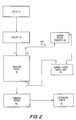
- tobacco to be treated is introduced to the dryer 10, where it is dried from about 19% to about 28% moisture (by weight) to from about 12% to about 21% moisture (by weight), preferably about 13% to about 16% moisture (by weight). Drying may be accomplished by any suitable means.
- This dried tobacco may be stored in bulk in a silo for subsequent impregnation and expansion or it may be fed directly to the pressure vessel 30 after suitable temperature adjustment and compaction, if necessary.
- a measured amount of dried tobacco is metered by a weighbelt and fed onto a conveyor belt within the tobacco cooling unit 20 for treatment prior to impregnation.
- the tobacco is cooled within the tobacco cooling unit 20 by any conventional means including refrigeration, to less than about 20°F (-6.7°C), preferably to less than about 0°F (-17.8°C), before being fed to the pressure vessel 30.
- FIG. 2A The block diagram of Figure 2A is similar to that of Figure 2 but additionally shows a compacting device 80 for compacting the tobacco prior to its impregnation with carbon dioxide according to the improved embodiment of the present invention.
- the tobacco may be compacted in situ in the pressure vessel or in a separate compacting station, or both.
- the compacting device 80 may be independent from or integral with the pressure vessel 30, and includes the appropriate compacting arrangement and transport arrangement.
- the compacting device 80 compresses or compacts the tobacco from an initial loose bulk density up to a compacted bulk density of from about 12 to about 16 lbs./cu.ft., and preferably about 13 to about 15 lbs./cu.ft. It has been observed that 15% OV tobacco compacted to more than about 15 or 16 lbs/cu.ft. exhibits some clumping after being removed from the impregnation vessel.
- the compacted bulk density of the tobacco is substantially uniform throughout the entire tobacco bed upon mechanical compaction.
- mechanical compaction provides a more uniform bulk density than would be achieved by gravity alone.
- the measured bulk density was between about 23 and about 25.5 lbs/cu.ft. essentially uniformly at measurement points between 0'' and about 20'' high in the bed, diminished to about 21 lbs/cu.ft. at about 31.5'' height, and then diminished essentially linearly from about 21 to about 14.5 lbs/cu.ft. between about 31.5'' and the top of the bed.
- the cooled and compacted tobacco is fed to the pressure vessel 30 through the tobacco inlet 31 where it is deposited.
- the pressure vessel 30 is a cylinder having a vertically extending longitudinal axis, with a carbon dioxide supply inlet 33 arranged at or near the bottom of the vessel 30 and a carbon dioxide vent outlet 32 arranged at or near the top of the vessel 30.
- venting may be achieved in any convenient direction, e.g., vertically, horizontally, radially, etc., because the process of the invention achieves substantially uniform temperatures throughout the tobacco bed due to the uniform controlled condensation of carbon dioxide.
- the bed is essentially homogenous and uniform and allows a uniform gas flow in any direction.
- the pressure vessel 30 is then purged with gaseous carbon dioxide, to remove any air or other non-condensible gases from the vessel 30.
- the pressure vessel may be evacuated using a vacuum-pump to remove air or other gases before carbon dioxide gas is introduced into the vessel. It is desirable that the purge be conducted in such a manner as not to significantly raise the temperature of the tobacco in the vessel 30.
- the effluent of this purge step is treated in any suitable manner to recover the carbon dioxide for reuse or it may be vented to atmosphere through line 34.
- carbon dioxide gas is introduced to the pressure vessel 30 from the supply tank 50 where it is maintained at about 400 psig to about 1050 psig (2758 kPa to 7239 kPa).
- the carbon dioxide outlet 32 is opened allowing the carbon dioxide to flow through the tobacco bed cooling the tobacco to a substantially uniform temperature while maintaining the pressure of the vessel 30 at from about 300 psig to about 500 psig (2068 kPa to 3447 kPa).
- the carbon dioxide outlet 32 is closed and the pressure of the vessel 30 is increased to from about 700 psig to about 1000 psig (4826 kPa to 6894 kPa), preferably about 800 psig (5515 kPa), by the addition of carbon dioxide gas. Then the carbon dioxide inlet 33 is closed. At this point, the tobacco bed temperature is approximately at the carbon dioxide saturation temperature.
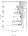
- FIG. 1 is a standard temperature (°F) - entropy (Btu/lb°F) diagram for carbon dioxide with line I-V drawn to illustrate one thermodynamic path in accord with the present invention.
- tobacco at about 65°F (18.3°C) is placed in a pressure vessel (at I) and the vessel pressure is increased to about 300 psig (2068 kPa) (as shown by line I-II).
- the vessel is then cooled to about 0°F (-17.8°C) by flow-thru cooling of carbon dioxide at about 300 psig (2068 kPa) (as shown by line II-III). Additional carbon dioxide gas is introduced to the vessel, raising the pressure to about 800 psig (5515 kPa) and the temperature to about 67°F (19.4°C). However, because the temperature of tobacco is below the saturation temperature of the carbon dioxide gas, a controlled amount of carbon dioxide gas will uniformly condense on the tobacco (as shown by line III-IV).
- the vessel After holding the system at about 800 psig (5515 kPa) for the desired length of time, the vessel is rapidly depressurized to atmospheric pressure resulting in a post-vent temperature of about -5°F to about -10°F (-20.6°C to -23.3°C) (as shown by line IV-V).
- In-situ cooling of the tobacco to about 10°F (-12.2°C) prior to pressurization generally will allow an amount of the saturated carbon dioxide gas to condense. Condensation generally will result in a substantially uniform distribution of liquid carbon dioxide throughout the tobacco bed. Evaporation of this liquid carbon dioxide during the vent step will help cool the tobacco in a uniform manner. A uniform post-impregnation tobacco temperature results in a more uniform expanded tobacco. The uniform condensation of carbon dioxide on the tobacco and the resultant uniform cooling of the tobacco is promoted because the tobacco has been ore-compressed to a substantially uniform bulk density.
- FIG 10 is a schematic diagram of the impregnation vessel 100 used in Run 28 showing the temperature, in °F, at various locations throughout the tobacco bed after venting.
- the tobacco-bed temperature at cross-section 120, 3 feet (914 mm) from the top of vessel 100 was found to have temperatures of about 11°F (-11.7°C) , 7°F (-14°C) , 7°F (-14°C), and 3°F (-16°C).
- about 1800 lbs (815 kg) of bright tobacco with an OV content of about 15% was placed in a 5 ft (i.d.) x 8.5 ft (ht) (1524 mm x 2591 mm) pressure vessel.
- the vessel was then purged with carbon dioxide gas for about 30 seconds before pressurizing to about 350 psig (2413 kPa) with carbon dioxide gas.
- the tobacco bed was then cooled to about 10°F (-12.2°C) by flow-thru cooling at 350 psig (2413 kPa) for about 12.5 minutes.
- the vessel pressure was then increased to about 800 psig (5515 kPa) and held for about 60 seconds before rapidly depressurizing in about 4.5 minutes.
- the temperature of the tobacco bed at various points was measured and found to be substantially uniform as shown in Figure 10. It was calculated that about 0.26 lbs. of carbon dioxide condensed per lb. of tobacco.
- the tobacco in the pressure vessel 30 is maintained under carbon dioxide pressure at about 800 psig (5515 kPa) for from about 1 second to about 300 seconds, preferably about 60 seconds. It has been discovered that tobacco contact time with carbon dioxide gas, i.e., the length of time that the tobacco must be maintained in contact with the carbon dioxide gas in order to absorb a desired amount of carbon dioxide, is influenced strongly by the tobacco OV content and the impregnation pressure used. Tobacco with a higher initial OV content requires less contact time at a given pressure than tobacco with a lower initial OV content in order to achieve a comparable degree of impregnation particularly at lower pressures. At higher impregnation pressures, the effect of tobacco OV on contact time with the carbon dioxide gas is reduced. This is illustrated in Table 3.
- the pressure vessel 30 is depressurized rapidly to atmospheric pressure in from about 1 second to about 300 seconds, depending on vessel size, by venting the carbon dioxide first to the carbon dioxide recovery unit 40 and then through line 34 to atmosphere. Carbon dioxide which has condensed on the tobacco is vaporized during this vent step, helping to cool the tobacco, resulting in a tobacco post-vent temperature of from about -35°F to about 20°F (-37.4°C to -6.7°C).
- the amount of carbon dioxide condensed in the tobacco is preferably in the range 0.1 to 0.9 pound of carbon dioxide per pound of tobacco.
- the best range is 0.1 to 0.3 pound per pound but amounts up to 0.5 or 0.6 pound per pound are suitable in some circumstances.
- Impregnated tobacco from the pressure vessel 30 may be expanded immediately by any suitable means, e.g., by feeding to the expansion tower 70.
- impregnated tobacco may be maintained for about 1 hour at its post-vent temperature in the tobacco transfer device 60 under a dry atmosphere, i.e., an atmosphere with a dewpoint below the post-vent temperature, for subsequent expansion.
- a dry atmosphere i.e., an atmosphere with a dewpoint below the post-vent temperature
- a 240 pound (109 kg) sample of bright tobacco filler with a 15% OV content was cooled to about 20°F (-6.7°C) and then placed in a pressure vessel approximately 2 feet (610 mm) in diameter and approximately 8 feet (2440 mm) in height.
- the vessel was then pressured to about 300 psig (2068 kPa) with carbon dioxide gas.
- the tobacco was then cooled, while maintaining the vessel pressure at about 300 psig (2068 kPa), to about 0°F (-17.8°C) by flushing with carbon dioxide gas near saturated conditions for about 5 minutes prior to pressurizing to about 800 psig (5515 kPa) with carbon dioxide gas.
- the vessel pressure was maintained at about 800 psig (5515 kPa) for about 60 seconds.
- the vessel pressure was decreased to atmospheric pressure by venting in about 300 seconds, after which the tobacco temperature was found to be about 0°F (-17.8°C) . Based on the tobacco temperature, the system pressure, temperature, and volume, and the tobacco post-vent temperature, it was calculated that approximately 0.29 lbs of carbon dioxide condensed per lb. of tobacco.
- the impregnated sample had a weight gain of about 2% which is attributable to the carbon dioxide impregnation.
- the impregnated tobacco was then, over a one hour period, exposed to heating in an 8-inch (203 mm) diameter expansion tower by contact with a 75% steam/air mixture at about 550°F (288°C) and a velocity of about 85 ft/sec (25.9 ms-1) for less than about 2 seconds.
- the product exiting the expansion tower had an OV content of about 2.8%.
- the product was equilibrated at standard conditions of 75°F (24°C) and 60%RH for about 24 hours. The filling power of the equilibrated product was measured by the standardized cylinder volume (CV) test.
- the vessel was then pressurized to about 800 psig (5515 kPa) with carbon dioxide gas. This pressure was maintained for about 60 seconds before the vessel was vented to atmospheric pressure in about 300 seconds.
- the impregnated tobacco was maintained in an environment with a dewpoint below the tobacco post-vent temperature prior to expansion.
- Figure 11 illustrates the effect of hold time after impregnation on the specific volume of expanded tobacco.
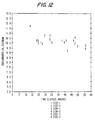
- Figure 12 illustrates the effect of hold time after impregnation on the equilibrated CV of expanded tobacco.
- a 19 pound sample of bright tobacco filler with a 15% OV content was placed in a 3.4 cubic foot (.096 m3) pressure vessel.
- the vessel was then pressured to about 185 psig (1276 kPa) with carbon dioxide gas.
- the tobacco was then cooled, while maintaining the vessel pressure at about 185 psig (1276 kPa), to about -25°F (-31.7°C) by flushing with carbon dioxide gas near saturated conditions for about 5 minutes prior to pressurizing to about 430 psig (2965 kPa) with carbon dioxide gas.
- the vessel pressure was maintained at about 430 psig (2965 kPa) for about 5 minutes.
- the vessel pressure was decreased to atmospheric pressure by venting in about 60 seconds, after which the tobacco temperature was found to be about -29°F (-33.9°C). Based on the tobacco temperature, the system pressure, temperature, and volume, it was calculated that approximately 0.23 lbs. of carbon dioxide condensed per lb. of tobacco.
- the impregnated sample had a weight gain of about 2% which is attributable to the carbon dioxide impregnation.
- the impregnated tobacco was then, over a one hour period, exposed to heating in a 3-inch (76.2 mm) diameter expansion tower by contact with a 100% steam at about 525°F (274°C) and a velocity of about 135 ft/sec (41 ms-1) for less than about 2 seconds.
- the product exiting the expansion tower had an OV content of about 3.8%.
- the product was equilibrated at standard conditions of 75°F (24°C) and 60%RH for about 24 hours. The filling power of the equilibrated product was measured by the standardized cylinder volume (CV) test.
- the process according to the invention may be advantageously adapted to a short-cycle impregnation of tobacco in relatively small batches, so that the process becomes essentially continuous.
- a preferred embodiment of such a process will now be described, as carried out in an apparatus according to the invention, with reference to Figures 14 to 19.
- the described embodiment is an example of a small-batch short-cycle impregnation process and apparatus to impregnate about 15% OV tobacco, at an output of approximately 500 pounds per hour with bulk density of about 14 lbs./cu.ft.
- Figure 14 is a schematic top view of an apparatus for carrying out the preferred process according to the invention.
- a stationary table 2' ( Figure 15) is mounted on a frame 1, and turntable 2 is mounted on the table 2'.
- Turntable 2 rotates counterclockwise (arrow R) about a substantially vertical axis A.
- An upper frame 1' carries a pressure vessel 30 as described below.
- the turntable 2 is driven to rotate (arrow R) in steps of substantially 90° by a drive arrangement, for example, an air actuator, a motor and blockable gear train or a stepper motor, which is not shown but which is generally understood by those skilled in the art.
- a drive arrangement for example, an air actuator, a motor and blockable gear train or a stepper motor, which is not shown but which is generally understood by those skilled in the art.
- Mounted on the turntable 2 as described below are four similar cylindrical tubes, namely tube 4 shwon in a feed or filling position, tube 5 shown in a pressing position, tube 6 shown below an impregnation station position, and tube 7 shown in a discharge position.
- each tube 4, 5, 6 and 7 is rotated in about 4 seconds to the respective following process station and held there for about 96 seconds as described below.
- FIG. 15 is a cylindrical sectional elevation of the apparatus of FIG. 14.
- the rotating turntable 2 is arranged directly above a stationary table 2', which is supported on frame 1.
- Conventional bearings may be provided to support turntable 2 on stationary table 2' to allow their relative rotational motion.
- the tubes 4, 5, 6 and 7 are each arranged in a corresponding hole in the turntable 2, so that each-tube remains open from the top and from the bottom through the turntable 2.
- a wiper 8 may be arranged at the bottom of each tube to wipe against table 2' to prevent tobacco from accululating in the space between turntable 2 and table 2'.
- a feed converyor 9 delivers loose bulk tobacco (e.g., 15% OV content tobacco) in an essentially continuous stream (arrow F) into a surge chute or surge tube 11.
- the tobacco may, for example, have been pretreated by a dryer 10 and a cooler 20 referenced in FIG. 2, before being delivered by feed conveyor 9.
- the tobacco falls through the surge tube 11 and through an open slide gate 12 into the tube 4 in the feed position.
- the tobacco feed rate is controlled so that tube 4 is filled substantially to the top during a one-station cycle time of about 96 seconds.
- Turntable 2 then rotates within about 4 seconds to move tube 4 into the compacting or pressing station occupied by tube 5 in the view of FIG. 15, corresponding generally to the compacting device 80 of FIG. 2a.
- slide gate 12 closes and stops the flow of loose tobacco, which then backs-up or stockpiles in surge tube 11 until the next tube (e.g. tube 7) is positioned below slide gate 12, whereupon slide gate 12 opens.
- Each tube is about 24'' in length, with an inner diameter of about 14'' and a wall thickness adequate to withstand compaction forces on the tobacco.
- a compaction piston assembly 13 is activated.
- the assembly corresponds generally to compacting device 80 of FIG. 2a and may, for example, be a hydraulically driven piston and cylinder. Piston assembly 13 compresses or compacts the tobacco to about half of its initial loose fill volume and about twice its initial loose fill bulk density, i.e., raising the bulk density to about 13 lbs./cu.ft.
- the compaction piston assembly 13 retracts before a one-station cycle time of about 96 seconds has expired. Then the tube containing compacted tobacco is rotated in about 4 seconds to the impregnation position of tube 6 and positioned in alignment with a hole 61 in table 2'.
- a pressure vessel piston assembly 14 moves from a position shown by broken lines below turntable 2, through hole 61 and through tube 6. Piston assembly 14 carries the pre-compacted tobacco out of tube 6 and into pressure vessel 30. Piston assembly 14 then compresses the tobacco further, to a bulk density of about 14 lbs./cu.ft. Then locking pin 15 locks piston assembly 14 into place, and the compressed tobacco is impregnated with carbon dioxide within pressure vessel 30 as more particularly described below.
- locking pin 15 is moved to an unlocked position, piston assembly 14 is withdrawn from pressure vessel 30, and simultaneously ejection piston 16 is driven downward to ensure that the impregnated bed of tobacco is completely cleared from the pressure vessel.
- tube 6 may be rotated to carry the impregnated tobacco to the discharge station to tube 7 in FIG. 15.
- a discharge assembly 3 such as a piston, moves down through tube 7 to assure that the impregnated tobacco is completely cleared from tube 7 and then retracts.
- the tobacco falls through a hole 71 in table 2' and into a discharge hopper assembly 17.
- Hopper assembly 17 is insulated and cooled with chilled, dry air (at a temperature below the post-vent tempterature of the tobacco) to preserve the carbon dioxide impregnation of the tobacco.
- Hopper assembly 17 includes a surge hopper 18 and a plurality of pinned doffers or soc-called opening rollers 19. The hopper assembly evens out the individual batches of impregnated tobacco (about 14 lbs.
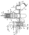
- FIG 16 is an enlarged sectional view of the pressure vessel arrangement 30 of Figure 15, after the pressure vessel piston 14 has pushed a pre-compacted tobacco bed (not shown for better clarity) into the pressure vessel, further compacted the tobacco, and been locked in place by locking pin 15.
- Pressure vessel 30 includes a cylinder 34 such as a cylinder obtainable from Autoclave Engineering, Inc. or Pressure Products, Inc. having a 14'' internal diameter. Cylinder 34 is preferably lined with a thermally insulating liner 35 having a wall thickness of about 0.125''.
- the ejection piston assembly 16 is arranged to move in the directions of arrow 16' through a hole fitted with a pressure seal 37 in the top 36 of the cylinder 34.
- a shaft 38 of piston assembly 16 carries an upper gas distributor plate 39a, an upper gas chamber plate 41a and an upper screen 42a.
- the screen 42a, plate 41a and plate 39a form an upper gas distributor assembly 58a, dimensioned to fit closely but movably within the insulating liner 35, with a wiper 43a arranged around the circumference of screen 42a.
- the piston assembly 14 includes a similar arrangement of a lower screen 42b with a wiper 43b, a lower gas chamber plate 41b and a lower gas distributor plate 39b.
- the components 42b, 41b and 39b form a lower gas distributor assembly 58b, dimensioned to fit slidably within the inner diameter of cylinder 34, e.g., less than about 14''.
- a tobacco containing cavity is formed, bounded radially by the inner walls of liner 35, on the top by screen 42a, and on the bottom by screen 42b.
- Pressure seal 37 around the shaft of ejection piston 16 and a pressure seal 44 around the upper portion of pressure vessel piston 14 are high pressure seals to confine the cabon dioxide gas at impregnation pressures.
- a low pressure seal 45a is arranged between gas distributor plate 39a and the top of the cylinder 34, and a low pressure seal 45b is arranged between the circumference of the lower gas distributor assembly 58 and the inner wall of cylinder 34.
- Low pressure seals 45a and 45b may be O-ring seals, which only need to withstand the low pressure differential across the respective gas distributor plates, gas chamber plates, screens and the tobacco bed.
- a control valve (not shown) is opened so that carbon dioxide gas is introduced (arrows 33') through gas inlets 33, then through gas plenum 46b, plates 39b and 41b and screen 42b to permeate the tobacco bed and flow out through the corresponding upper components 42a, 41a, 39a, 46a and 32.
- inlets 33 are arranged at or near the bottom of plenum 46b to allow any condensate to drain, and outlets 32 are arranged at or near the top of plenum 46a to allow any heat of compression to vent rather than forming trapped "hot spots".
- Vacuum purging is especially applicable to the pressure vessel of the present embodiment, because it contains a relatively low gas volume and a sufficient vacuum may be achieved in about 5 seconds.
- the upper control valve is fully open to allow an air purge for about 5 seconds. Then the upper control valve is throttled to a pressure of about 250 psig, whereupon the pressure vessel pressures-up to about 250 psig in about 2 seconds while a very small amount of gas may still escape through the upper control valve.
- saturated carbon dioxide gas at about 250 psig is allowed to flow through the bed for about 56 seconds. The bed of tobacco is cooled uniformly to saturation conditions for the carbon dioxide at about 250 psig (see e.g., Figure 1).
- the upper control valve is throttled to about 800 psig, whereupon carbon dioxide flows into the bed and pressures-up to about 800 psig in about 6 seconds while a very small amount of gas may still escape through the upper control valve.
- the saturation temperature of the gas increases (also uniformly throughout the bed), so carbon dioxide condenses onto the cool tobacco uniformly through the bed.
- the tobacco temperature lags behind the increasing saturation temperature of the carbon dioxide gas.
- condensate may continue to form until the pressure reaches about 800 psig.
- This short-cycle impregnation process according to the invention can be completed in about 100 seconds, because the purging, pressurization and venting steps can be carried out very quickly, and because a high pressure "soak time" as well as additional steps to overcome heat of compression can be eliminated.
- the cooling effect brings the tobacco bed temperature uniformly to about O°F. or less in this example.
- the post vent temperature can be controlled by controlling pre-cooling of the tobacco and the pressure-up cycle parameters, such as the flow-through pressure and the maximum pressure, in order to control the amount of condensation achieved. Therefore, uniform cooling, impregnation and post-vent stability can be achieved regardless of bed density.
- a further advantage of the short-cycle impregnation process according to the invention is that an essentially continuous output of about 500 to 520 lbs./hr. is achieved by operating as described with a total per-batch cycle time of about 100 seconds and a batch weight of about 14 to 15 pounds (about 15% initial OV tobacco compacted to about 14 lbs./cu.ft.) .
- the above described example embodiment was designed to achieve a rated output of just over 500 lbs./hr. Other output rates can be achieved simply by appropriately redesigning apparatus dimensions and process variables.
- Figure 17 is a schematic top view of a further variation of the apparatus described above. This apparatus is similar to the one described above and operates in a generally similar manner, but combines the filling position with the compacting position.
- each tube 4, 6 and 7 is rotated in about 4 seconds to the respective following process station and held there for about 102 seconds as described below.
- Figure 18 is a cylindrical sectional elevation of the apparatus of Figure 17.
- the description referring to Figure 15 generally applies to Figure 18.
- Tube 4 includes an upper tube 4a, which rotates on turntable 2, and a lower tube 4b, which is mounted in stationary table 2'. As turntable 2 rotates to successive stopped positions, tubes 4a, 6 and 7 will sequentially be aligned over lower tube 4b.
- a respective compaction sleeve 4', 6' and 7' is positioned in each tube 4a, 6 and 7.
- each sleeve 4', 6' and 7' is about 13'' long, with an inner diameter of about 13.5'' and a wall thickness of about 0.25''.
- the sleeves fit closely but movably within the respective tube 4a, 6 or 7.
- Each sleeve preferably is made of a thermally insulating material and preferably is perforated by several pressure equalization holes as described below.
- the feed rate of tobacco is controlled so that a desired amount of tobacco is filled into tube 4b and sleeve 4' in about 90 seconds. Then slide plate 12 is closed and compacting backup plate 48 moves (arrow 48') into position at the top of tube 4a in about 2 seconds. Alternatively, components 12 and 48 may be combined in one assembly. Then compactor 13 compacts the tobacco in about 10 seconds. The starting position of compactor 13 can be adjusted depending on the desired amount of tobacco per charge. Turntable 2 then rotates within about 4 seconds to move tube 4a and sleeve 4' filled with compacted tobacco into the impregnation position of tube 6.
- a pressure vessel piston assembly 14 moves from a position shown by broken lines below table 2', through hole 61 and through tube 6. Piston assembly 14 carries the compaction sleeve 6' and pre-compacted tobacco contained in the sleeve out of tube 6 and into pressure vessel 30. Then locking pin 15 locks piston assembly 14 into place, sand the compressed tobacco is impregnated with carbon dioxide within pressure vessel 30 generally as described above.
- Locking pin 15 is moved to an unlocked position, piston assembly 14 is withdrawn from pressure vessel 30, and simultaneously ejection piston 16 is driven downward to ensure that compaction sleeve 6' and the impregnated bed of tobacco is completely cleared from the pressure vessel.
- piston assembly 14 is clear of the bottom of tube 6 and piston 16 is retracting back toward its starting position, tube 6 may be rotated to carry sleeve 6' containing the impregnated tobacco within tube 6 to the discharge station of tube 7 in Figure 18.
- Figure 19 is an enlarged sectional view of the pressure vessel arrangement 30 of Figure 18, after the pressure vessel piston 14 has pushed compaction sleeve 6' containing a pre-compacted tobacco bed (not shown for better clarity) into the pressure vessel and been locked in place by locking pin 15.
- Cylinder 34 in this embodiment is not lined with a thermally insulating liner 35, but rather receives the insulating sleeve 6'.
- a tobacco containing cavity is formed, bounded radially by the inner walls of sleeve 6', on the top by screen 42a, and on the bottom by screen 42b.
- a low pressure seal 45a is arranged between gas distributor assembly 58a and top of cylinder 34.
- Low pressure seal 52a mounted on the assembly 58a is arranged between assembly 58a and the top edge of sleeve 6'.
- Low pressure seal 52b is arranged between assembly 58b and the bottom edge of sleeve 6'.
- Low pressure seals 45a and 52a mounted on the assembly 58a, and seals 45b and 52b mounted on assembly 58b, may be O-ring seals, which only need to withstand the low pressure differential across the respective gas distributor plates, gas chamber plates, screens and tobacco bed. These seals ensure that gas is properly distributed through the screens rather than passing along the walls of the pressure vessel.
- the sleeve 6' may be perforated by holes 6'' to ensure that no pressure differential exists across the wall of the sleeve.
- outlets 32 are arranged in the top of the cylinder 34, to vent upwards (arrows 32').
- Gas plenum 46a is formed as a cavity within the upper distributor assembly 58a.
- the impregnation process is similar to that described above, and summarized in Table 4. However, in this embodiment, the pressure-up to about 250 psig is achieved in about 2 seconds, the flow-through at about 250 psig is carried out for about 61 seconds, and the pressure-up to about 800 psig is achieved in about 7 seconds. Thus the total impregnation cycle requires about 102 seconds.
- the tube in which the compacted tobacco was impregnated had an internal diameter of 4.724 inch (120mm) and a height of 12 inch (305 mm), giving a volume of 0.1217 cu.ft. (3.45 cc).
- a blend of bright and burley tobaccos at a ratio of approximately 4 to 1 was cut at different initial OV contents as indicated in Table 5 below.
- the compacted tobacco in the impregnation tube was at various bulk densities as shown in Table 5.
- Carbon dioxide gas was introduced into the bottom of the vessel and the pressure increased to 230 to 250 psig (1586 -1723.5 kPa), at which pressure the CO2 gas was allowed to flow through the tobacco until the temperature at the top of the tobacco bed was about -2°F.
- the outlet of the top of the bessel was then closed and the pressure increased to 700-800 psig (4826-5515 Kpa). Within one minute of achieving the maximum pressure the vessel was depressurized by releasing gas from both the top and the bottom of the vessel.
- Table 5 shows the results of several tests at different initial bulk densities and OV contents.
- the "Flowthru ratio” represents the ratio of the weight of CO2 used for cooling to the weight of tobacco.
- the “Flowthru end temp” is that at which the vessel is closed.
- the "Average PVT” is the post vent temperature of the tobacco after release of the pressure and "Average CO2 Ret” is the weight of CO2 retained in the tobacco after venting, expressed as a percentage of the total weight.
- the impregnation vessel When the process according to the invention is carried out at a small-batch, short-cycle impregnation in an essentially continuously operating apparatus as described, the impregnation vessel may become cooled further on each cycle. If so, then condensation or frosting may occur. If the "snowball effect" is problematic under the desired operating conditions, heaters 35a and 35b, or thermal insulation, can be arranged in the gas plenums as shown in Figure 16 and Figure 19.
- the thermally insulating liner 35 of Figure 16 and sleeve 6; of Figure 19 serves the same purpose of insulating the metal cylinder 34 from the cold tobacco bed and gas.
- the heaters can be controlled, for example to be activated between impregnation cycles, in order to prevent ever-increasing chilling and resultant frosting of the metal surfaces.
- hot gas such as heated air at about 70 to about 150°F, can be directed into the pressure vessel between impregnation cycles.
Abstract
Description
- This invention relates to a process for expanding the volume of tobacco. More particularly this invention relates to expanding tobacco using carbon dioxide.
- The tobacco art has long recognized the desirability of expanding tobacco to increase the bulk or volume of tobacco. There have been various reasons for expanding tobacco. One of the early purposes for expanding tobacco involved making up the loss of weight caused by the tobacco curing process. Another purpose was to improve the smoking characteristics of particular tobacco components, such as tobacco stems. It has also been desired to increase the filling power of tobacco so that a smaller amount of tobacco would be required to produce a smoking product, such as a cigarette, which would have the same firmness and yet would deliver lower tar and nicotine than a comparable smoking product made of non-expanded tobacco having a more dense tobacco filler.
- Various methods have been proposed for expanding tobacco, including the impregnation of tobacco with a gas under pressure and the subsequent release of pressure, whereby the gas causes expansion of the tobacco cells to increase the volume of the treated tobacco. Other methods which have been employed or suggested have included the treatment of tobacco with various liquids, such as water or relatively volatile organic or inorganic liquids, to impregnate the tobacco with the same, after which the liquids are driven off to expand the tobacco. Additional methods which have been suggested have included the treatment of tobacco with solid materials which, when heated, decompose to produce gases which serve to expand the tobacco. other methods include the treatment of tobacco with gas-containing liquids, such as carbon dioxide-containing water, under pressure to incorporate the gas in the tobacco and when the impregnated tobacco is heated or the ambient pressure reduced the tobacco expands. Additional techniques have been developed for expanding tobacco which involved the treatment of tobacco with gases which react to form solid chemical reaction products within the tobacco, which solid reaction products may then decompose by heat to produce gases within the tobacco which cause expansion of tobacco upon their release. More specifically:
- U.S. Patent No. 1,789,435 describes a method and apparatus for expanding the volume of tobacco in order to make up the loss of volume caused in curing tobacco leaf. To accomplish this object, the cured and conditioned tobacco is contacted with a gas, which may be air, carbon dioxide or steam under pressure and the pressure is then relieved, the tobacco tends to expand. The patent states that the volume of the tobacco may, by that process, be increased to the extent of about 5-15%.
- U.S. Patent No. 3,771,533, commonly assigned herewith, involves a treatment of tobacco with carbon dioxide and ammonia gases, whereby the tobacco is saturated with these gases and ammonium carbamate is formed in situ. The ammonium carbamate is thereafter decomposed by heat to release the gases within the tobacco cells and to cause expansion of the tobacco.
- U.S. Patent No. 4,258,729, commonly assigned herewith, describes a method for expanding the volume of tobacco in which the tobacco is impregnated with gaseous carbon dioxide under conditions such that the carbon dioxide remains substantially in the gaseous state. Pre-cooling the tobacco prior to the impregnation step or cooling the tobacco bed by external means during impregnation is limited to avoid condensing the carbon dioxide to any significant degree.
- U.S. Patent No. 4,235,250, commonly assigned herewith, describes a method for expanding the volume of tobacco in which the tobacco is impregnated with gaseous carbon dioxide under conditions such that the carbon dioxide remains substantially in the gaseous state. During depressurization some of the carbon dioxide is converted to a partially condensed state within the tobacco. That patent teaches that the carbon dioxide enthalpy is controlled in such a manner to minimize carbon dioxide condensation.
- U.S. Patent No. RE. 32,013, commonly assigned herewith, describes a method and apparatus for expanding the volume of tobacco in which the tobacco is impregnated with liquid carbon dioxide, converting the liquid carbon dioxide or solid carbon dioxide in situ, and then causing the solid carbon dioxide to vaporize and expand the tobacco.
- Copending and commonly-assigned U.S. Patent application 07/717,064, filed June 18, 1991, and the corresponding European Application No.92305534.7 published under No. 0519696 A1 on 23rd December 1992 discloses a process for impregnating tobacco with carbon dioxide and then expanding the tobacco. That disclosed process includes steps of contacting tobacco with gaseous carbon dioxide and controlling process conditions to cause a controlled amount of carbon dioxide to condense on the tobacco.
- It has been found that with gaseous carbon dioxide impregnation processes, the tobacco must achieve a sufficiently low exit temperature at the end of the process (after the venting of carbon dioxide from maximum pressure) in order for the tobacco to be successfully impregnated. During venting, the escaping carbon dioxide lowers the temperature of the tobacco bed.
- Prior processes for impregnating tobacco using gaseous carbon dioxide without controlled condensation cannot achieve sufficient cooling of a high bulk density tobacco bed because cooling is provided only by gas expansion. As the bulk density of the tobacco bed increases, the mass of tobacco to be cooled increases and the volume or void space remaining within the tobacco bed and the available gas for cooling decreases. Without sufficient cooling, an acceptable pre-expansion stability of the impregnated tobacco cannot be achieved.
- Typically, a loosely filled tobacco bed exhibits a tobacco bulk density gradient with a higher bulk density toward the bottom due to the compressing effect of the weight of the column of tobacco. Tobacco expansion processes using gaseous carbon dioxide and loosely filled tobacco beds of relatively low bulk density may result in non-uniform cooling of the tobacco and thus non-uniform stability and expansion of the tobacco.
- The bulk density at the bottom of a deep tobacco bed may be the limiting factor in a gas-only process, because the tobacco at the bottom of a deep bed may have too great a bulk density to be efficiently cooled by gas expansion cooling. As a result, tobacco expansion processes using yaseous carbon dioxide are limited to relatively small or shallow tobacco beds. While such small beds have been used for experimental development, they were not usually commercially practical.
- It has now been found that, whereas a high bulk density prevents successful use of the prior expansion processes using gaseous carbon dioxide, the process of our EP-0 519 696 A1 using controlled condensation of the carbon dioxide gas is useable at high bulk densities and in particular on tobacco which has initially been compacted. This has the advantage of a process which gives greater throughput.
- The compaction may be effected by straightforward compression of a batch of tobacco or by processing steps such as cutting.
- In the process of the present invention the tobacco is initially compacted to a bulk density not less than 10lb/cu.ft. (160.2 kg/m³) . The bulk density preferably does not exceed 20lb/cu.ft. (320.4 kg/m³) bulk densities of 12 to 16 lb/cu.ft. (192.2 to 256.3 kg/m³), preferably 13 to 15 lb/cu.ft. (208.2 to 240.3 kg/m³), are advantageous. The compacted tobacco is cooled before it is impregnated with CO₂ under pressure. This cooling may be effected by flowing CO₂ gas through the tobacco. In the impregnation stage the CO₂ gas is at or near saturation and when it contacts the tobacco sufficient of the CO₂ is condensed on the tobacco to ensure that when the pressure is subsequently released expansion of the carbon dioxide gas and evaporation of the condensed carbon dioxide lower the temperature of the impregnated tobacco to a temperature in the range -35° to 20°F (-37.4° to -6.7°C).
- Subsequently the impregnated tobacco is expanded in conventional manner, for example by heating at atmospheric pressure.
- Tobacco impregnated according to the present invention may be expanded using less energy, e.g., a significantly lower temperature gas stream may be used at a comparable residence time, than tobacco impregnated under conditions where liquid carbon dioxide is used.
- In addition, the present invention affords greater control of the chemical and flavor components, e.g., reducing sugars and alkaloids, in the final tobacco product by allowing expansion to be carried out over a greater temperature range than was practical in the past.
- Furthermore, impregnating and expanding tobacco according to the present invention can achieve a greater process throughput than processes using gaseous carbon dioxide under conditions that do not result in condensation of the carbon dioxide prior to venting. According to the present invention, evaporation of condensed carbon dioxide provides sufficient cooling so that even tobacco of a substantially high bulk density may be effectively impregnated and expanded. This evaporation cooling is preferable in high bulk density tobacco beds for achieving a sufficiently low post-vent tobacco temperature to ensure stability of the impregnated tobacco.
- It has been found that when practicing the present invention the post-vent tobacco temperature is essentially independent of tobacco bulk density. The invention is applicable to both large and small batch operation.
- The compression or compaction of the tobacco before impregnation not only results in a desirably high bulk density but also gives a more uniform density throughout the bed. Thereby, in addition to further ensuring uniformity of carbon dioxide impregnation, the mass throughput of the process may be increased.
- The process throughput may also be increased by loading the impregnator to higher tobacco bulk densities in accordance with one of the preferred embodiments of the present invention. Also, the compacted tobacco bed is less likely than a loose tobacco bed to settle due to gravity or gas flow which may otherwise create an undesirable void space in the impregnator. Additionally, less heat of compression develops because a smaller volume of gas is compressed per pound of tobacco. The condensed carbon dioxide on the tobacco at the latter stages of pressurization avoids the localization of heat of compression. Because of the sufficiently low post-vent temperatures achieved, the process of the invention achieves acceptable carbon dioxide retention and stability after impregnation even with a high bulk density of tobacco.
- The increased process throughput due to increased mass throughput achieves greater cost economy in production, or allows capital cost savings by reducing the size of the process equipment. Furthermore, a small-batch, short-cycle process operates as an essentially continuous process carried out in a preferred apparatus as described below.
- The reduced quantity of carbon dioxide gas required with elevated bulk densities also achieves environmental benefits, because less gas is vented to the atmosphere per pound of tobacco.
- The above and other objects and advantages of the invention will be apparent upon consideration of the following detailed description and representative examples, taken in conjunction with the accompanying drawings, in which:
- Figure 1 is a standard temperature-entropy diagram for carbon dioxide;
- Figure 2 is a simplified block diagram of a process for expanding tobacco as described in EP-A-0 519 696.
- Figure 2A is a variant of Figure 2 showing a process for compacting, impregnating and expanding tobacco according to one embodiment of the present invention;
- Figure 3 is a plot of weight percent carbon dioxide evolved from tobacco impregnated at 250 psia (1723.5 kPa) and -18°C versus post-impregnation time for tobacco with an OV content of about 12%, 14%, 16.2%, and 20%;
- Figure 4 is a plot of weight percent carbon dioxide retained in the tobacco versus post-vent time for three different OV tobaccos;
- Figure 5 is a plot of expanded tobacco equilibrium CV versus hold-time before expansion for tobacco with an OV content of about 12% and about 21%;
- Figure 6 is a plot of expanded tobacco specific volume versus hold-time before expansion for tobacco with an OV content of about 12% and about 21%;
- Figure 7 is a plot of expanded tobacco equilibrium CV versus expansion tower exit OV content;
- Figure 8 is a plot of percent reduction in tobacco reducing sugars versus expansion tower exit OV content;
- Figure 9 is a plot of percent reduction in tobacco alkaloids versus expansion tower exit OV content;
- Figure 10 is a schematic diagram of an impregnation vessel showing the tobacco temperature at various points throughout the tobacco bed after venting;
- Figure 11 is a plot of expanded tobacco specific volume versus hold-time after impregnation prior to expansion;
- Figure 12 is a plot of expanded tobacco equilibrium CV versus hold-time after impregnation prior to expansion; and
- Figure 13 is a plot of tobacco temperature versus tobacco OV showing the amount of pre-cooling required to achieve adequate stability (e.g., about 1 hour post-vent hold before expansion) for tobacco impregnated at 800 psig (5515 kPa);
- Figure 14 is a schematic top view of an embodiment of an apparatus for carrying out a short cycle impregnation process on high bulk density tobacco according to the invention;
- Figure 15 is a schematic sectional elevation of the apparatus of Figure 14;
- Figure 16 is an enlarged section through the pressure vessel of Figure 15, viewed in essentially the same direction as the viewing direction of Figure 15;
- Figure 17 is a top view similar to that of Figure 14, but of another embodiment of the apparatus of the invention;
- Figure 18 is a view similar to that of Figure 15, but of the apparatus of Figure 17;
- Figure 19 is a view similar to that of Figure 16, but of the apparatus of Figure 18;
- The present invention relates broadly to a process for expanding tobacco employing a readily available, relatively inexpensive, non-combustible and non-toxic expansion agent. More particularly, the present invention relates to the production of an expanded tobacco product of substantially reduced density and increased filling power, produced by impregnating tobacco under pressure with saturated gaseous carbon dioxide and a controlled amount of condensed liquid carbon dioxide, rapidly releasing the pressure, and then causing the tobacco to expand. Expansion may be accomplished by subjecting the impregnated tobacco to heat, radiant energy or similar energy generating conditions which will cause the carbon dioxide impregnant to rapidly expand.
- To carry out the process of the present invention one may treat either whole cured tobacco leaf, tobacco in cut or chopped form, or selected parts of tobacco such as tobacco stems or possibly even reconstituted tobacco. In comminuted form, the tobacco to be impregnated preferably has a particle size of from about 6 mesh to about 100 mesh, more preferably the tobacco has a particle size not less than about 30 mesh. As used herein, mesh refers to United States standard sieve and those values reflect the ability of more than 95% of the particles of a given size to pass through a screen of a given mesh value.
- As used herein, % moisture may be considered equivalent to oven-volatiles content (OV) since not more than about 0.9% of tobacco weight is volatiles other than water. Oven volatiles determination is a simple measurement of tobacco weight loss after exposure for 3 hours in a circulating air oven controlled at 212°F (100°C) . The weight loss as percentage of initial weight is oven-volatiles content.
- Generally, the tobacco to be treated will have an OV content of at least about 12% and less than about 21%. Preferably, the tobacco to be treated will have an OV content of about 13% to about 16%. Below about 12% OV, tobacco is too easily broken, resulting in a large amount of tobacco fines. Above about 21% OV, excessive amounts of pre-cooling are needed to achieve acceptable stability and a very low post-vent temperature is required, resulting in a brittle tobacco which is easily broken.
- According to the present invention, in order to achieve a desirable high bulk density or a more uniform density throughout the tobacco bed, or both a high bulk density and a more uniform tobacco bed, the tobacco is compacted or compressed before it is impregnated with carbon dioxide. The tobacco may be compacted before it is placed in the pressure vessel, within the pressure vessel or both, so that the resultant bulk density of the tobacco in the pressure vessel is essentially uniform and substantially greater than the bulk density of a typical loose fill tobacco.
- For a batch impregnation process, the tobacco-containing pressure vessel is preferably purged with carbon dioxide gas, the purging operation generally taking from about 1 minute to about 4 minutes. In the preferred embodiment involving a high bulk density bed of tobacco, purge requirements may be reduced because void space may be minimized and because the vessel may be smaller per pound of tobacco. The example described in detail below with reference to Figures 14-16 operates with only a 5 second purge step. The purging step may be eliminated without detriment to the final product. The benefits of purging are the removal of gases that may interfere with carbon dioxide recovery and the removal of foreign gases that may interfere with full penetration of the carbon dioxide.
- The gaseous carbon dioxide which is employed in the process of this invention will generally be obtained from a supply tank where it is maintained in saturated liquid form at a pressure of from about 400 psig to about 1050 psig (2758 kPa to 7239 kPa). The supply tank may be fed with recompressed gaseous carbon dioxide vented from the pressure vessel. Additional carbon dioxide may be obtained from a storage vessel where it is maintained in liquid form generally at a pressure of from about 215 psig to about 305 psig (1482 kPa to 2103 kPa) and temperatures of from about -20°F to about 0°F (-28.9°C to -17.8°C). The liquid carbon dioxide from the storage vessel may be mixed with the recompressed gaseous carbon dioxide and stored in the supply tank. Alternatively, liquid carbon dioxide from the storage vessel may be preheated, for example, by suitable heating coils around the feed line, to a temperature of about 0°F to about 84°F (-17.8°C to 29°C) and a pressure of about 300 psig to about 1000 psig (2068 kPa to 6894 kPa) before being introduced into the pressure vessel. After the carbon dioxide is introduced into the pressure vessel, the interior of the vessel, including the tobacco to be treated, will generally be at a temperature of from about 20°F to about 80°F (-6.7°C to 26.7°C) and a pressure sufficient to maintain the carbon dioxide gas at or substantially at a saturated state.
- Tobacco stability, i.e. the length of time the impregnated tobacco may be stored after depressurisation before the final expansion step and still be satisfactorily expanded, is dependent on the initial tobacco OV content, i.e., pre-impregnation OV content, and the tobacco temperature after venting of the pressure vessel. Tobacco with a higher initial OV content requires a lower tobacco post-vent temperature than tobacco with a lower initial OV content to achieve the same degree of stability.
- The effect of OV content on the stability of tobacco impregnated with carbon dioxide gas at 250 psia (1723.5 kPa) and -18°C was determined by placing a weighed sample of bright tobacco, typically about 60g to about 70g, in a 300 cc pressure vessel. The vessel was then immersed in a temperature controlled bath set at -18°C. After the vessel reached thermal equilibrium with the bath, the vessel was purged with carbon dioxide gas. The vessel was then pressured to about 250 psia (1723.5 kPa). Gas phase impregnation was assured by maintaining the carbon dioxide pressure at least 20 psi to 30 psi (1379 kPa to 2068 kPa) below the carbon dioxide saturation pressure at -18°C. After allowing the tobacco to soak at pressure for about 15 minutes to about 60 minutes the vessel pressure was rapidly decreased to atmospheric pressure in about 3 seconds to about 4 seconds by venting to atmosphere. The vent valve was immediately closed and the tobacco remained in the pressure vessel immersed in the temperature controlled bath at -18°C for about 1 hour. After about 1 hour, the vessel temperature was increased to about 25°C over about two hours in order to liberate the carbon dioxide remaining in the tobacco. The vessel pressure and temperature were continually monitored using an IBM compatible computer with
LABTECH version 4 data acquisition software from Laboratories Technologies Corp. The amount of carbon dioxide evolved by the tobacco over time at a constant temperature, can be calculated based on the vessel pressure over time. - Figure 3 compares the stability of about 12%, 14%, 16.2% and 20% OV bright tobacco impregnated with carbon dioxide gas at 250 psia (1723.5 kPa) at -18°C as described above. Tobacco with an OV content of about 20% lost about 71% of its carbon dioxide pickup after 15 minutes at -18°C, while tobacco with an OV content of about 12% lost only about 25% of its carbon dioxide pickup after 60 minutes. The total amount of carbon dioxide evolved after increasing the vessel temperature to 25°C is an indication of the total carbon dioxide pickup. This data indicates that, for impregnations at comparable pressures and temperatures, as tobacco OV content increases, tobacco stability decreases.
- In order to achieve sufficient tobacco stability, it is preferred that the tobacco temperature be approximately about 0°F to about 10°F (-17.8°C to -12.2°C) after venting of the pressure vessel when the tobacco to be expanded has an initial OV content of about 15%. Tobacco with an initial OV content greater than about 15% should have a post-vent temperature lower than about 0°F to about 10°F (-17.8°C to -12.2°C) and tobacco with an initial OV content less than 15% may be maintained at a temperature greater than about 0°F to about 10°F (-17.8°C to -12.2°C) in order to achieve a comparable degree of stability. For example, Figure 4 illustrates the effect of tobacco post-vent temperature on tobacco stability at various OV contents. Figure 4 shows that tobacco with a higher OV content, about 21%, requires a lower post-vent temperature, about -35°F (-37.4°C), in order to achieve a similar level of carbon dioxide retention over time as compared to a tobacco with a lower OV content, about 12%, with a post-vent temperature of about 0°F to about 10°F (-17.8°C to -12.2°C). Figures 5 and 6, respectively, show the effect of tobacco OV content and post-vent temperature on equilibrated CV and specific volume of tobacco expanded after being held at its indicated post-vent temperature for the indicated time.
- Figures 4, 5 and 6 are based on data from Runs 49, 54 and 65. In each of these runs, bright tobacco was placed in a pressure vessel with a total volume of 3.4 cubic feet (.096m³), 2.4 cubic feet (.068m³) of which was occupied by the tobacco. In Runs 54 and 65, approximately 22 lbs. (9.97 kg) of 20% OV tobacco was placed in the pressure vessel. This tobacco was pre-cooled by flowing carbon dioxide gas through the vessel at about 421 psig (2902 kPa) and at about 153 psig (1055 kPa) for
Runs - Impregnation pressure, mass ratio of carbon dioxide to tobacco, and heat capacity of tobacco can be manipulated in such a manner that under specific circumstances, the amount of cooling required from the evaporation of condensed carbon dioxide is small relative to the cooling provided by the expansion of carbon dioxide gas upon depressurization. However, as the mass ratio of carbon dioxide gas to tobacco decreases, i.e., as the tobacco bulk density increases, the cooling required from the evaporation of condensed carbon dioxide increases. In order to achieve increased process throughput and more uniform tobacco expansion by pre-compacting the tobacco, it is essential to achieve the controlled formation and evaporation of condensed carbon dioxide.
- In each of Runs 49, 54, and 65, after reaching the impregnation pressure of about 800 psig (5515 kPa), the system pressure was held at about 800 psig (5515 kPa) for about 5 minutes before the vessel was rapidly depressurized to atmospheric pressure in approximately 90 seconds. The mass of carbon dioxide condensed per lb. of tobacco during pressurization after cooling was calculated for
Runs TABLE 1 Run 54 65 Feed OV% 20.5 20.4 Tobacco Wt. (lbs.) 22.5 21.25 (10/2 kg) (9.63kg) CO₂ flow-thru cooling press. (psig) 421 153 (2902 kPa) (1055 kPa) Impreg.press (psig) 800 772 (5515 kPa) (5322 kPa) Pre-cool temp (°F) 10 -20 (12.2°C) (-29.9°C) Post-vent temp. (°F) 10-20 -35 (12.2°C) (-37.4°C) to -6.7°C) Expansion Tower gas temp (°F) 575 575 (302°C) (302°C) Eq CV (cc/g) 8.5 10.0 SV (cc/g) 1.8 2.5 Calculated CO₂ condensed (lb./lb.tob) 0.19 0.58 - The term "cylinder volume" is a unit for measuring the degree of expansion of tobacco. As used throughout this application, the values employed, in connection with these terms are determined as follows:
- Tobacco filler weighing 20 grams, if unexpanded, or 10 grams, if expanded, is placed in a 6-cm diameter Densimeter cylinder, Model No. DD-60, designed by the Heinr. Borgwaldt Company, Heinr. Borgwaldt GmbH, Schnackenburgallee No. 15,
Postfack 54 07 02, 2000Hamburg 54 West Germany. A 2 kg piston, 5.6 cm in diameter, is placed on the tobacco in the cylinder for 30 seconds. The resulting volume of the compressed tobacco is read and divided by the tobacco sample weight to yield the cylinder volume as cc/gram. The test determines the apparent volume of a given weight of tobacco filler. The resulting volume of filler is reported as cylinder volume. This test is carried out at standard environmental conditions of 75°F (24°C) and 60% RH; conventionally, unless otherwise stated, the sample is preconditioned in this environment for 24-48 hours. - The term "specific volume" is a unit for measuring the volume and true density of solid objects, e.g., tobacco, using the fundamental principles of the ideal gas law. The specific volume is determined by taking the inverse of the density and is expressed as "cc/g". A weighed sample of tobacco, either "as is", dried at 100°C for 3 hours, or equilibrated, is placed in a cell in a Quantachrome Penta-Pycnometer. The cell is then purged and pressured with helium. The volume of helium displaced by the tobacco is compared with volume of helium required to fill an empty sample cell and the tobacco volume is determined based on Archimedes' principle. As used throughout this application, unless stated to the contrary, specific volume was determined using the same tobacco sample used to determine OV, i.e., tobacco dried after exposure for 3 hours in a circulating air oven controlled at 100°C.
- The degree of tobacco stability required, and hence, the desired tobacco post-vent temperature, is dependent on many factors including the length of time after depressurization and before expansion of the tobacco. Therefore, the selection of a desired post-vent temperature should be made in light of the degree of stability required. According to another aspect of the process according to the invention taught therein, the impregnated tobacco is handled between the impregnation and expansion steps so as to maintain the tobacco's retention of carbon dioxide. For example, the tobacco should be conveyed by an insulated and cooled conveyor, and should be isolated from any moisture laden air.
- The desired tobacco post-vent temperature may be obtained by any suitable means including pre-cooling of the tobacco before introducing it to the pressure vessel, in-situ cooling of the tobacco in the pressure vessel by purging with cold carbon dioxide or other suitable means, or vacuum cooling in situ augmented by flow through of carbon dioxide gas. Vacuum cooling has the advantage of reducing the tobacco OV content without thermal degradation of the tobacco. Vacuum cooling also removes non-condensible gases from the vessel, thereby allowing the purging step to be eliminated. Vacuum cooling can be effectively and practically used to reduce the tobacco temperature to as low as about 30°F (-1°C). It is preferred that the tobacco is cooled in situ in the pressure vessel.
- The amount of pre-cooling or in-situ cooling required to achieve the desired tobacco post-vent temperature is dependent on the amount of cooling provided by the expansion of the carbon dioxide gas during depressurization. The amount of tobacco cooling due to the expansion of the carbon dioxide gas is a function of the ratio of the mass of the carbon dioxide gas to the mass of tobacco, the heat capacity of the tobacco, the final impregnation pressure, and the system temperature. Therefore, for a given impregnation, when the tobacco feed and the system pressure, temperature and volume are fixed, control of the final post-vent temperature of the tobacco may be achieved by controlling the amount of carbon dioxide permitted to condense on the tobacco. The amount of tobacco cooling due to evaporation of the condensed carbon dioxide from the tobacco is a function of the ratio of the mass of condensed carbon dioxide to the mass of tobacco, the heat capacity of the tobacco, and the temperature or pressure of the system.
- With the presence of condensed carbon dioxide, changes in bulk density do not significantly affect post vent temperatures. When the tobacco is compacted prior to impregnation with carbon dioxide, a greater bulk density results and allows a greater tobacco mass to be filled into a given impregnation vessel. The increase in tobacco bulk density can increase the production rate of the process. Although the preferred embodiment describes execution of the compacting step to achieve greater bulk density as including mechanical compaction with a piston, any alternative, or non-mechanical methods or apparatus for compacting tobacco could be utilized.
- The required tobacco stability is determined by the specific design of the impregnation and expansion processes used. Figure 13 illustrates the tobacco post-vent temperature required to achieve the desired tobacco stability as a function of OV for a particular process design. The lower
shaded area 200 illustrates the amount of cooling contributed by carbon dioxide gas expansion and theupper area 250 illustrates the amount of additional cooling required by carbon dioxide liquid evaporation as a function of tobacco OV to provide the required stability. For this example, adequate tobacco stability is achieved when the tobacco temperature is at or below the temperature shown by the "stability" line. The process variables which determine the tobacco post-vent temperature include the variables discussed previously and other variables including, but not limited to, vessel temperature, vessel mass, vessel volume, vessel configuration, flow geometry, equipment orientation, heat transfer rate to the vessel walls, and process designed retention time between impregnation and expansion. - For the 800 psig (5515 kPa) process illustrated in Figure 13, with a post-vent hold time of about 1 hour, no pre-cooling is required for 12% OV tobacco to achieve the required stability, whereas 21% OV tobacco requires sufficient pre-cooling to achieve a post-vent temperature of about -35°F (-37.4°C).
- The desired tobacco post-vent temperature of from about -35°F to about 20°F (-37.4°C to -6.7°C), is significantly higher than the post-vent temperature -- about -110°F (-79°C) -- when liquid carbon dioxide is used as the impregnant. This higher tobacco post-vent temperature and lower tobacco OV allow the expansion step to be conducted at a significantly lower temperature, resulting in an expanded tobacco with less toasting and less loss of flavor. In addition, less energy is required to expand the tobacco. moreover, because very little, if any, solid carbon dioxide is formed, handling of the impregnated tobacco is simplified. Unlike tobacco impregnated with only liquid carbon dioxide, tobacco impregnated according to the present invention does not tend to form clumps which must be mechanically broken. Thus, a greater usable-tobacco yield is achieved because the clump-breaking step which results in tobacco fines too small for use in cigarettes is eliminated.
- Moreover, about 21% OV tobacco at about -35°F (-37.4°C) to about 12% OV tobacco at about 20°F (-6.7°C), unlike any OV tobacco at about -110°F (-79°C), is not brittle and, therefore, is handled with minimum degradation. This property results in a greater yield of usable tobacco because less tobacco is mechanically broken during normal handling, e.g., during unloading of the pressure vessel or transfer from the pressure vessel to the expansion zone.
- Chemical changes during expansion of the impregnated tobacco, e.g., loss of reducing sugars and alkaloids upon heating, can be reduced by increasing the exit tobacco OV, i.e. the tobacco OV content immediately after expansion, to about 6% OV or higher. This can be accomplished by reducing the temperature of the expansion step. Normally, an increase in tobacco exit OV is coupled with a decrease in the amount of expansion achieved. The decrease in the amount of expansion depends strongly on the starting feed OV content of the tobacco. As the tobacco feed OV is reduced to approximately 13%, minimal reduction in the degree of expansion is observed even at a tobacco moisture content of about 6% or more exiting the expansion device. Therefore, if the feed OV and the expansion temperature are reduced, surprisingly good expansion can be attained while chemical changes are minimized. This is shown in Figures 7, 8 and 9.
- Figures 7, 8 and 9 are based on data from Runs 2241 through 2242 and 2244 through 2254. This data is tabulated in Table 2. In each of these runs a measured amount of bright tobacco was placed in a pressure vessel similar to the vessel described in Example 1.


- Liquid carbon dioxide at 430 psig (2964 kPa) was used to impregnate the tobacco in Runs 2241 and 2242. The tobacco was allowed to soak in the liquid carbon dioxide for about 60 seconds before the excess liquid was drained. The vessel was then rapidly depressurized to atmospheric pressure, forming solid carbon dioxide in situ. The impregnated tobacco was then removed from the vessel and any clumps which may have formed were broken. The tobacco was then expanded in an 8-inch (203 mm) expansion tower by contact with a 75% steam/air mixture set at the indicated temperature and a velocity of about 85 ft/sec (25.9 ms-1) for less than about 4 seconds.
- The nicotine alkaloids and reducing sugars content of the tobacco prior to and after expansion were measured using a Bran Luebbe (formerly Technicon) continuous flow analysis system. An aqueous acetic acid solution is used to extract the nicotine alkaloids and reducing sugars from the tobacco. The extract is first subjected to dialysis which removes major interferences of both determinations. Reducing sugars are determined by their reaction with p-hydroxybenzoic acid hydrazide in a basic medium at 85°C to form a colour. Nicotine alkaloids are determined by their reaction with cyanogen chloride, in the presence of aromatic amine. A decrease in the alkaloids or the reducing sugars content of the tobacco is indicative of a loss of or change in chemical and flavour components of the tobacco.
-
Runs 2244 through 2254 were impregnated with gaseous carbon dioxide at 800 psig (5515 kPa) according to the method described in Example 1 (below). In order to study the effect of expansion temperature, tobacco from a single impregnation was expanded at different temperatures. For example, 325 lbs. (147 kg) of tobacco were impregnated and then three samples, taken over the course of about 1 hour, were tested and expanded at 500°F (260°C), 550°F (288°C), and 600°F (315.5°C), representingRuns 2244, 2245, and 2246, respectively. In order to study the effect of OV content, batches of tobacco with OV contents of about 13%, 15%, 17%, and 19% were impregnated. The notation 1st, 2nd, or 3rd next to the run number indicates the order in which the tobacco was expanded from a particular impregnation. The impregnated tobacco was expanded in an 8-inch (203 mm) expansion tower by contact with a 75% steam/air mixture set at the indicated temperature and a velocity of about 85 ft/sec (25.9 ms-1) for less than about 4 seconds. The alkaloids and reducing sugars content of the tobacco were measured in the same manner as described above. - Referring to Figure 2, tobacco to be treated is introduced to the
dryer 10, where it is dried from about 19% to about 28% moisture (by weight) to from about 12% to about 21% moisture (by weight), preferably about 13% to about 16% moisture (by weight). Drying may be accomplished by any suitable means. This dried tobacco may be stored in bulk in a silo for subsequent impregnation and expansion or it may be fed directly to thepressure vessel 30 after suitable temperature adjustment and compaction, if necessary. - Optionally, a measured amount of dried tobacco is metered by a weighbelt and fed onto a conveyor belt within the
tobacco cooling unit 20 for treatment prior to impregnation. The tobacco is cooled within thetobacco cooling unit 20 by any conventional means including refrigeration, to less than about 20°F (-6.7°C), preferably to less than about 0°F (-17.8°C), before being fed to thepressure vessel 30. - The block diagram of Figure 2A is similar to that of Figure 2 but additionally shows a compacting
device 80 for compacting the tobacco prior to its impregnation with carbon dioxide according to the improved embodiment of the present invention. The tobacco may be compacted in situ in the pressure vessel or in a separate compacting station, or both. Thus, the compactingdevice 80 may be independent from or integral with thepressure vessel 30, and includes the appropriate compacting arrangement and transport arrangement. - With 15% OV tobacco, the compacting
device 80 compresses or compacts the tobacco from an initial loose bulk density up to a compacted bulk density of from about 12 to about 16 lbs./cu.ft., and preferably about 13 to about 15 lbs./cu.ft. It has been observed that 15% OV tobacco compacted to more than about 15 or 16 lbs/cu.ft. exhibits some clumping after being removed from the impregnation vessel. - For a small impregnator (e.g., about one cubic foot), the compacted bulk density of the tobacco is substantially uniform throughout the entire tobacco bed upon mechanical compaction. For a large impregnator, mechanical compaction provides a more uniform bulk density than would be achieved by gravity alone. For example, when bright tobacco of 25% OV was loosely filled into a cylinder about 69'' high and about 24'' in diameter, the measured bulk density was between about 23 and about 25.5 lbs/cu.ft. essentially uniformly at measurement points between 0'' and about 20'' high in the bed, diminished to about 21 lbs/cu.ft. at about 31.5'' height, and then diminished essentially linearly from about 21 to about 14.5 lbs/cu.ft. between about 31.5'' and the top of the bed. if a tobacco bed is compacted to at least the threshold bulk density, the gravitational compacting effect is negligible, and the bulk density will be substantially uniform throughout the bed.
- The following procedure was used to measure bulk density at diufferent depths in a tobacco bed. Pre-weighed amounts of tobacco, e.g., 40 pound amounts, were placed one after another into a cylinder. A marker was placed into the cylinder after each 40 pound amount of tobacco. When the cylinder was filled with tobacco, with markers interposed between successive 40 pound amounts of tobacco, the cylinder was carefully removed to leave standing a column of tobacco and markers. The height of each marker was measured and used to calculate the volume occupied by, and the bulk density of, the associated 40 pound amount of tobacco.
- The cooled and compacted tobacco is fed to the
pressure vessel 30 through thetobacco inlet 31 where it is deposited. Preferably, thepressure vessel 30 is a cylinder having a vertically extending longitudinal axis, with a carbondioxide supply inlet 33 arranged at or near the bottom of thevessel 30 and a carbondioxide vent outlet 32 arranged at or near the top of thevessel 30. However, venting may be achieved in any convenient direction, e.g., vertically, horizontally, radially, etc., because the process of the invention achieves substantially uniform temperatures throughout the tobacco bed due to the uniform controlled condensation of carbon dioxide. Furthermore, the bed is essentially homogenous and uniform and allows a uniform gas flow in any direction. - The
pressure vessel 30 is then purged with gaseous carbon dioxide, to remove any air or other non-condensible gases from thevessel 30. Alternatively, the pressure vessel may be evacuated using a vacuum-pump to remove air or other gases before carbon dioxide gas is introduced into the vessel. It is desirable that the purge be conducted in such a manner as not to significantly raise the temperature of the tobacco in thevessel 30. Preferably, the effluent of this purge step is treated in any suitable manner to recover the carbon dioxide for reuse or it may be vented to atmosphere throughline 34. - Following the purge step, carbon dioxide gas is introduced to the
pressure vessel 30 from thesupply tank 50 where it is maintained at about 400 psig to about 1050 psig (2758 kPa to 7239 kPa). When the inside pressure of thevessel 30 reaches from about 300 psig to about 500 psig (2068 kPa to 3447 kPa), thecarbon dioxide outlet 32 is opened allowing the carbon dioxide to flow through the tobacco bed cooling the tobacco to a substantially uniform temperature while maintaining the pressure of thevessel 30 at from about 300 psig to about 500 psig (2068 kPa to 3447 kPa). After a substantially uniform tobacco temperature is reached, thecarbon dioxide outlet 32 is closed and the pressure of thevessel 30 is increased to from about 700 psig to about 1000 psig (4826 kPa to 6894 kPa), preferably about 800 psig (5515 kPa), by the addition of carbon dioxide gas. Then thecarbon dioxide inlet 33 is closed. At this point, the tobacco bed temperature is approximately at the carbon dioxide saturation temperature. While pressures as high as 1050 psig (7239 kPa) might be economically employed, and a pressure equal to the critical pressure of carbon dioxide, 1057 psig (7287 kPa), would be acceptable, there is no known upper limit to the useful impregnation pressure range, other than that imposed by the capabilities of the equipment available and the effects of supercritical carbon dioxide on the tobacco. - During pressurization of the pressure vessel, a thermodynamic path is followed that allows a controlled amount of the saturated carbon dioxide gas to condense on the tobacco. Figure 1 is a standard temperature (°F) - entropy (Btu/lb°F) diagram for carbon dioxide with line I-V drawn to illustrate one thermodynamic path in accord with the present invention. For example, tobacco at about 65°F (18.3°C) is placed in a pressure vessel (at I) and the vessel pressure is increased to about 300 psig (2068 kPa) (as shown by line I-II). The vessel is then cooled to about 0°F (-17.8°C) by flow-thru cooling of carbon dioxide at about 300 psig (2068 kPa) (as shown by line II-III). Additional carbon dioxide gas is introduced to the vessel, raising the pressure to about 800 psig (5515 kPa) and the temperature to about 67°F (19.4°C). However, because the temperature of tobacco is below the saturation temperature of the carbon dioxide gas, a controlled amount of carbon dioxide gas will uniformly condense on the tobacco (as shown by line III-IV). After holding the system at about 800 psig (5515 kPa) for the desired length of time, the vessel is rapidly depressurized to atmospheric pressure resulting in a post-vent temperature of about -5°F to about -10°F (-20.6°C to -23.3°C) (as shown by line IV-V).
- In-situ cooling of the tobacco to about 10°F (-12.2°C) prior to pressurization generally will allow an amount of the saturated carbon dioxide gas to condense. Condensation generally will result in a substantially uniform distribution of liquid carbon dioxide throughout the tobacco bed. Evaporation of this liquid carbon dioxide during the vent step will help cool the tobacco in a uniform manner. A uniform post-impregnation tobacco temperature results in a more uniform expanded tobacco. The uniform condensation of carbon dioxide on the tobacco and the resultant uniform cooling of the tobacco is promoted because the tobacco has been ore-compressed to a substantially uniform bulk density.
- This uniform tobacco temperature is illustrated in Figure 10, which is a schematic diagram of the
impregnation vessel 100 used inRun 28 showing the temperature, in °F, at various locations throughout the tobacco bed after venting. For example, the tobacco-bed temperature atcross-section vessel 100, was found to have temperatures of about 11°F (-11.7°C) , 7°F (-14°C) , 7°F (-14°C), and 3°F (-16°C). about 1800 lbs (815 kg) of bright tobacco with an OV content of about 15% was placed in a 5 ft (i.d.) x 8.5 ft (ht) (1524 mm x 2591 mm) pressure vessel. The vessel was then purged with carbon dioxide gas for about 30 seconds before pressurizing to about 350 psig (2413 kPa) with carbon dioxide gas. The tobacco bed was then cooled to about 10°F (-12.2°C) by flow-thru cooling at 350 psig (2413 kPa) for about 12.5 minutes. The vessel pressure was then increased to about 800 psig (5515 kPa) and held for about 60 seconds before rapidly depressurizing in about 4.5 minutes. The temperature of the tobacco bed at various points was measured and found to be substantially uniform as shown in Figure 10. It was calculated that about 0.26 lbs. of carbon dioxide condensed per lb. of tobacco. - Returning to Figure 2, the tobacco in the
pressure vessel 30 is maintained under carbon dioxide pressure at about 800 psig (5515 kPa) for from about 1 second to about 300 seconds, preferably about 60 seconds. It has been discovered that tobacco contact time with carbon dioxide gas, i.e., the length of time that the tobacco must be maintained in contact with the carbon dioxide gas in order to absorb a desired amount of carbon dioxide, is influenced strongly by the tobacco OV content and the impregnation pressure used. Tobacco with a higher initial OV content requires less contact time at a given pressure than tobacco with a lower initial OV content in order to achieve a comparable degree of impregnation particularly at lower pressures. At higher impregnation pressures, the effect of tobacco OV on contact time with the carbon dioxide gas is reduced. This is illustrated in Table 3.
- After the tobacco has soaked sufficiently, the
pressure vessel 30 is depressurized rapidly to atmospheric pressure in from about 1 second to about 300 seconds, depending on vessel size, by venting the carbon dioxide first to the carbondioxide recovery unit 40 and then throughline 34 to atmosphere. Carbon dioxide which has condensed on the tobacco is vaporized during this vent step, helping to cool the tobacco, resulting in a tobacco post-vent temperature of from about -35°F to about 20°F (-37.4°C to -6.7°C). - The amount of carbon dioxide condensed in the tobacco is preferably in the range 0.1 to 0.9 pound of carbon dioxide per pound of tobacco. The best range is 0.1 to 0.3 pound per pound but amounts up to 0.5 or 0.6 pound per pound are suitable in some circumstances.
- Impregnated tobacco from the
pressure vessel 30 may be expanded immediately by any suitable means, e.g., by feeding to theexpansion tower 70. Alternatively, impregnated tobacco may be maintained for about 1 hour at its post-vent temperature in thetobacco transfer device 60 under a dry atmosphere, i.e., an atmosphere with a dewpoint below the post-vent temperature, for subsequent expansion. After expansion and, if desired, reordering, the tobacco may be used in the manufacture of tobacco products, including cigarettes. - The following examples are illustrative:
- A 240 pound (109 kg) sample of bright tobacco filler with a 15% OV content was cooled to about 20°F (-6.7°C) and then placed in a pressure vessel approximately 2 feet (610 mm) in diameter and approximately 8 feet (2440 mm) in height. The vessel was then pressured to about 300 psig (2068 kPa) with carbon dioxide gas. The tobacco was then cooled, while maintaining the vessel pressure at about 300 psig (2068 kPa), to about 0°F (-17.8°C) by flushing with carbon dioxide gas near saturated conditions for about 5 minutes prior to pressurizing to about 800 psig (5515 kPa) with carbon dioxide gas. The vessel pressure was maintained at about 800 psig (5515 kPa) for about 60 seconds. The vessel pressure was decreased to atmospheric pressure by venting in about 300 seconds, after which the tobacco temperature was found to be about 0°F (-17.8°C) . Based on the tobacco temperature, the system pressure, temperature, and volume, and the tobacco post-vent temperature, it was calculated that approximately 0.29 lbs of carbon dioxide condensed per lb. of tobacco.
- The impregnated sample had a weight gain of about 2% which is attributable to the carbon dioxide impregnation. The impregnated tobacco was then, over a one hour period, exposed to heating in an 8-inch (203 mm) diameter expansion tower by contact with a 75% steam/air mixture at about 550°F (288°C) and a velocity of about 85 ft/sec (25.9 ms-1) for less than about 2 seconds. The product exiting the expansion tower had an OV content of about 2.8%. The product was equilibrated at standard conditions of 75°F (24°C) and 60%RH for about 24 hours. The filling power of the equilibrated product was measured by the standardized cylinder volume (CV) test. This gave a CV value of 9.4 cc/g at an equilibrium moisture content of 11.4%. An unexpanded control was found to have a cylinder volume of 5.3 cc/g at an equilibrium moisture content of 12.2%. The sample after processing, therefore, had a 77% increase in filling power as measured by the CV method.
- The effect of hold time after impregnation prior to expansion on expanded tobacco SV and equilibrated CV was studied in Runs 2132-1 through 2135-2. In each of these runs, 2132-1, 2132-2, 2134-1, 2134-2, 2135-1, and 2135-2, 225 lbs. of bright tobacco with a 15% OV content was placed in the same pressure vessel as described in Example 1. The vessel was pressured to from about 250 psig to about 300 psig (1723 kPa to 2068 kPa) with carbon dioxide gas. The tobacco was then cooled, while maintaining the vessel pressure at about 250 psig to about 300 psig (1723 kPa to 2068 kPa), in the same manner as described in Example 1. The vessel was then pressurized to about 800 psig (5515 kPa) with carbon dioxide gas. This pressure was maintained for about 60 seconds before the vessel was vented to atmospheric pressure in about 300 seconds. The impregnated tobacco was maintained in an environment with a dewpoint below the tobacco post-vent temperature prior to expansion. Figure 11 illustrates the effect of hold time after impregnation on the specific volume of expanded tobacco. Figure 12 illustrates the effect of hold time after impregnation on the equilibrated CV of expanded tobacco.
- A 19 pound sample of bright tobacco filler with a 15% OV content was placed in a 3.4 cubic foot (.096 m3) pressure vessel. The vessel was then pressured to about 185 psig (1276 kPa) with carbon dioxide gas. The tobacco was then cooled, while maintaining the vessel pressure at about 185 psig (1276 kPa), to about -25°F (-31.7°C) by flushing with carbon dioxide gas near saturated conditions for about 5 minutes prior to pressurizing to about 430 psig (2965 kPa) with carbon dioxide gas. The vessel pressure was maintained at about 430 psig (2965 kPa) for about 5 minutes. The vessel pressure was decreased to atmospheric pressure by venting in about 60 seconds, after which the tobacco temperature was found to be about -29°F (-33.9°C). Based on the tobacco temperature, the system pressure, temperature, and volume, it was calculated that approximately 0.23 lbs. of carbon dioxide condensed per lb. of tobacco.
- The impregnated sample had a weight gain of about 2% which is attributable to the carbon dioxide impregnation. The impregnated tobacco was then, over a one hour period, exposed to heating in a 3-inch (76.2 mm) diameter expansion tower by contact with a 100% steam at about 525°F (274°C) and a velocity of about 135 ft/sec (41 ms-1) for less than about 2 seconds. The product exiting the expansion tower had an OV content of about 3.8%. The product was equilibrated at standard conditions of 75°F (24°C) and 60%RH for about 24 hours. The filling power of the equilibrated product was measured by the standardized cylinder volume (CV) test. This gave an equilibrated CV value of 10.1 cc/g at an equilibrium moisture of 11.0%. An unexpanded control was found to have a cylinder volume of 5.8 cc/g at an equilibrium moisture of 11.6%. The sample after processing, therefore, had a 74% increase in filling power as measured by the CV method.
- As already described, the process according to the invention may be advantageously adapted to a short-cycle impregnation of tobacco in relatively small batches, so that the process becomes essentially continuous. A preferred embodiment of such a process will now be described, as carried out in an apparatus according to the invention, with reference to Figures 14 to 19. The described embodiment is an example of a small-batch short-cycle impregnation process and apparatus to impregnate about 15% OV tobacco, at an output of approximately 500 pounds per hour with bulk density of about 14 lbs./cu.ft.
- Figure 14 is a schematic top view of an apparatus for carrying out the preferred process according to the invention. A stationary table 2' (Figure 15) is mounted on a
frame 1, andturntable 2 is mounted on the table 2'.Turntable 2 rotates counterclockwise (arrow R) about a substantially vertical axis A. An upper frame 1' carries apressure vessel 30 as described below. - The
turntable 2 is driven to rotate (arrow R) in steps of substantially 90° by a drive arrangement, for example, an air actuator, a motor and blockable gear train or a stepper motor, which is not shown but which is generally understood by those skilled in the art. Mounted on theturntable 2 as described below are four similar cylindrical tubes, namelytube 4 shwon in a feed or filling position,tube 5 shown in a pressing position,tube 6 shown below an impregnation station position, andtube 7 shown in a discharge position. As the drive arrangement rotatesturntable 2 in 90° rotational steps, eachtube - FIG. 15 is a cylindrical sectional elevation of the apparatus of FIG. 14. The
rotating turntable 2 is arranged directly above a stationary table 2', which is supported onframe 1. Conventional bearings may be provided to supportturntable 2 on stationary table 2' to allow their relative rotational motion. Thetubes turntable 2, so that each-tube remains open from the top and from the bottom through theturntable 2. Awiper 8 may be arranged at the bottom of each tube to wipe against table 2' to prevent tobacco from accululating in the space betweenturntable 2 and table 2'. - A
feed converyor 9 delivers loose bulk tobacco (e.g., 15% OV content tobacco) in an essentially continuous stream (arrow F) into a surge chute orsurge tube 11. The tobacco may, for example, have been pretreated by adryer 10 and a cooler 20 referenced in FIG. 2, before being delivered byfeed conveyor 9. The tobacco falls through thesurge tube 11 and through anopen slide gate 12 into thetube 4 in the feed position. The tobacco feed rate is controlled so thattube 4 is filled substantially to the top during a one-station cycle time of about 96 seconds.Turntable 2 then rotates within about 4 seconds to movetube 4 into the compacting or pressing station occupied bytube 5 in the view of FIG. 15, corresponding generally to the compactingdevice 80 of FIG. 2a. - While the
turntable 2 rotates between successive stopped positions as described, theslide gate 12 closes and stops the flow of loose tobacco, which then backs-up or stockpiles insurge tube 11 until the next tube (e.g. tube 7) is positioned belowslide gate 12, whereupon slidegate 12 opens. - Each tube is about 24'' in length, with an inner diameter of about 14'' and a wall thickness adequate to withstand compaction forces on the tobacco. When a filled tube is in the pressing position of
tube 5, acompaction piston assembly 13 is activated. The assembly corresponds generally to compactingdevice 80 of FIG. 2a and may, for example, be a hydraulically driven piston and cylinder.Piston assembly 13 compresses or compacts the tobacco to about half of its initial loose fill volume and about twice its initial loose fill bulk density, i.e., raising the bulk density to about 13 lbs./cu.ft. - After compressing the tobacco, the
compaction piston assembly 13 retracts before a one-station cycle time of about 96 seconds has expired. Then the tube containing compacted tobacco is rotated in about 4 seconds to the impregnation position oftube 6 and positioned in alignment with ahole 61 in table 2'. A pressurevessel piston assembly 14 moves from a position shown by broken lines belowturntable 2, throughhole 61 and throughtube 6.Piston assembly 14 carries the pre-compacted tobacco out oftube 6 and intopressure vessel 30.Piston assembly 14 then compresses the tobacco further, to a bulk density of about 14 lbs./cu.ft. Then lockingpin 15locks piston assembly 14 into place, and the compressed tobacco is impregnated with carbon dioxide withinpressure vessel 30 as more particularly described below. - Thereafter, locking
pin 15 is moved to an unlocked position,piston assembly 14 is withdrawn frompressure vessel 30, and simultaneouslyejection piston 16 is driven downward to ensure that the impregnated bed of tobacco is completely cleared from the pressure vessel. Oncepiston assembly 14 is clear of the bottom oftube 6 andpiston 16 is retracting back toward its starting position,tube 6 may be rotated to carry the impregnated tobacco to the discharge station totube 7 in FIG. 15. - A
discharge assembly 3, such as a piston, moves down throughtube 7 to assure that the impregnated tobacco is completely cleared fromtube 7 and then retracts. The tobacco falls through ahole 71 in table 2' and into adischarge hopper assembly 17.Hopper assembly 17 is insulated and cooled with chilled, dry air (at a temperature below the post-vent tempterature of the tobacco) to preserve the carbon dioxide impregnation of the tobacco.Hopper assembly 17 includes asurge hopper 18 and a plurality of pinned doffers or soc-calledopening rollers 19. The hopper assembly evens out the individual batches of impregnated tobacco (about 14 lbs. each in this example) into a continuoue bulk flow D of tobacco and reconfigures the shape of the tobacco flow D to prevent "choke-feeding" the expansion apparatus. Tobacco experiences a period of retention in thehopper assembly 17 for a period of time referred to in the art as bulking time. The extent of bulking time is dependent upon the frequency at which thehopper assembly 17 receives tobacco from the impregnator. A shorter impregnation cycle reduces the bulking time for each batch of tobacco, lessening stability requirements of carbon dioxide retention within the tobacco. Because CO₂ stability has an inverse relationship with the post-vent exit temperature of the tobacco, a shorter cycle provides not only effective operation at reduced stability, but can also do so as higher post-vent exit temperatures than a longer cycle. - Figure 16 is an enlarged sectional view of the
pressure vessel arrangement 30 of Figure 15, after thepressure vessel piston 14 has pushed a pre-compacted tobacco bed (not shown for better clarity) into the pressure vessel, further compacted the tobacco, and been locked in place by lockingpin 15.Pressure vessel 30 includes acylinder 34 such as a cylinder obtainable from Autoclave Engineering, Inc. or Pressure Products, Inc. having a 14'' internal diameter.Cylinder 34 is preferably lined with a thermally insulatingliner 35 having a wall thickness of about 0.125''. Theejection piston assembly 16 is arranged to move in the directions of arrow 16' through a hole fitted with apressure seal 37 in the top 36 of thecylinder 34. Ashaft 38 ofpiston assembly 16 carries an uppergas distributor plate 39a, an uppergas chamber plate 41a and anupper screen 42a. - The
screen 42a,plate 41a andplate 39a form an uppergas distributor assembly 58a, dimensioned to fit closely but movably within the insulatingliner 35, with awiper 43a arranged around the circumference ofscreen 42a. At the opposite end ofpressure vessel 30, thepiston assembly 14 includes a similar arrangement of alower screen 42b with awiper 43b, a lowergas chamber plate 41b and a lowergas distributor plate 39b. Thecomponents gas distributor assembly 58b, dimensioned to fit slidably within the inner diameter ofcylinder 34, e.g., less than about 14''. - Thus, a tobacco containing cavity is formed, bounded radially by the inner walls of
liner 35, on the top byscreen 42a, and on the bottom byscreen 42b.Pressure seal 37 around the shaft ofejection piston 16 and apressure seal 44 around the upper portion ofpressure vessel piston 14 are high pressure seals to confine the cabon dioxide gas at impregnation pressures. Alow pressure seal 45a is arranged betweengas distributor plate 39a and the top of thecylinder 34, and alow pressure seal 45b is arranged between the circumference of the lower gas distributor assembly 58 and the inner wall ofcylinder 34. Low pressure seals 45a and 45b may be O-ring seals, which only need to withstand the low pressure differential across the respective gas distributor plates, gas chamber plates, screens and the tobacco bed. Theseseals - In order to impregnate the compacted tobacco with carbon dioxide a control valve (not shown) is opened so that carbon dioxide gas is introduced (arrows 33') through
gas inlets 33, then throughgas plenum 46b,plates screen 42b to permeate the tobacco bed and flow out through the correspondingupper components - As carbon dioxide gas flows in, air is purged from the tobacco bed and escapes through
screen 42a,platres gas plenum 46a throughgas outlets 32 to a control valve (not shown) by which gas may be vented to atmosphere or recovered in a recovery arrangement 40 (Figure 2). Preferably,inlets 33 are arranged at or near the bottom ofplenum 46b to allow any condensate to drain, andoutlets 32 are arranged at or near the top ofplenum 46a to allow any heat of compression to vent rather than forming trapped "hot spots". - Alternatively, air or other gases may be purged from the pressure vessel by applying a vacuum to the vessel. Vacuum purging is especially applicable to the pressure vessel of the present embodiment, because it contains a relatively low gas volume and a sufficient vacuum may be achieved in about 5 seconds.
- Initially, the upper control valve is fully open to allow an air purge for about 5 seconds. Then the upper control valve is throttled to a pressure of about 250 psig, whereupon the pressure vessel pressures-up to about 250 psig in about 2 seconds while a very small amount of gas may still escape through the upper control valve. In order to cool the tobacco according to the invention, saturated carbon dioxide gas at about 250 psig is allowed to flow through the bed for about 56 seconds. The bed of tobacco is cooled uniformly to saturation conditions for the carbon dioxide at about 250 psig (see e.g., Figure 1).
- Then, the upper control valve is throttled to about 800 psig, whereupon carbon dioxide flows into the bed and pressures-up to about 800 psig in about 6 seconds while a very small amount of gas may still escape through the upper control valve. As the pressure increases uniformly throughout the bed), the saturation temperature of the gas increases (also uniformly throughout the bed), so carbon dioxide condenses onto the cool tobacco uniformly through the bed. As the condensation warms the tobacco, the tobacco temperature lags behind the increasing saturation temperature of the carbon dioxide gas. Thus, condensate may continue to form until the pressure reaches about 800 psig.
- It has been found that for selected pressures of about 750 psig or greater, for about 15% OV tobacco, no additional "soak time" is required at the selected high pressure in order to achieve sufficient impregnation. Therefore, when about 800 psig pressure is attained, the upper and lower control valves are both opened to aloow venting of carbon dioxide through
inlets 33 as well as outlets 32 (upper and lower arrows 32') for about 15 seconds back down to atmospheric pressure. The time required for venting may be reduced by venting the bed from both the top and the bottom. This short-cycle process to produce about 500 pounds per hour of impregnated tobacco at about 14 lbs./cu.ft. density is summarized below in Table 4. This short-cycle impregnation process according to the invention can be completed in about 100 seconds, because the purging, pressurization and venting steps can be carried out very quickly, and because a high pressure "soak time" as well as additional steps to overcome heat of compression can be eliminated.TABLE 4 - OPERATION SEQUENCE APPROX.TIME OPERATION (seconds) 4 move pressure vessel piston and ejection piston up to charge tobacco 2 lock locking pin 5 flow CO₂ to purge air 2 pressure-up to 250 psig 56 flow-through CO₂ at 250 psig 6 pressure-up to 800 psig 0 flow-through "soak time" at 800 psig 15 vent 2 unlock locking pin 4 move pressure vessel piston and ejection piston down to remove tobacco from impregnator 4 rotate table about 90° 100 Approx. batch cycle time - During venting, some cooling is provided by expansion of the gas, but the majority of cooling is provided by evaporation of condensed carbon dioxide. The cooling effect brings the tobacco bed temperature uniformly to about O°F. or less in this example. The post vent temperature can be controlled by controlling pre-cooling of the tobacco and the pressure-up cycle parameters, such as the flow-through pressure and the maximum pressure, in order to control the amount of condensation achieved. Therefore, uniform cooling, impregnation and post-vent stability can be achieved regardless of bed density.
- A further advantage of the short-cycle impregnation process according to the invention is that an essentially continuous output of about 500 to 520 lbs./hr. is achieved by operating as described with a total per-batch cycle time of about 100 seconds and a batch weight of about 14 to 15 pounds (about 15% initial OV tobacco compacted to about 14 lbs./cu.ft.) . In fact, the above described example embodiment was designed to achieve a rated output of just over 500 lbs./hr. Other output rates can be achieved simply by appropriately redesigning apparatus dimensions and process variables.
- Figure 17 is a schematic top view of a further variation of the apparatus described above. This apparatus is similar to the one described above and operates in a generally similar manner, but combines the filling position with the compacting position.
- In this embodiment, three similar cylindrical tubes, namely
tube 4 shown in a feed or filling position,tube 6 shown below in impregnation station position, andtube 7 shown in a discharge position. As the drive arrangement rotatesturntable 2 in 120° rotational steps, eachtube - Figure 18 is a cylindrical sectional elevation of the apparatus of Figure 17. The description referring to Figure 15 generally applies to Figure 18. However, only three tubes, 4, 6 and 7, are each arranged in a corresponding hole in the
turntable 2.Tube 4 includes an upper tube 4a, which rotates onturntable 2, and alower tube 4b, which is mounted in stationary table 2'. Asturntable 2 rotates to successive stopped positions,tubes lower tube 4b. A respective compaction sleeve 4', 6' and 7' is positioned in eachtube respective tube - The feed rate of tobacco is controlled so that a desired amount of tobacco is filled into
tube 4b and sleeve 4' in about 90 seconds. Then slideplate 12 is closed and compactingbackup plate 48 moves (arrow 48') into position at the top of tube 4a in about 2 seconds. Alternatively,components compactor 13 compacts the tobacco in about 10 seconds. The starting position ofcompactor 13 can be adjusted depending on the desired amount of tobacco per charge.Turntable 2 then rotates within about 4 seconds to move tube 4a and sleeve 4' filled with compacted tobacco into the impregnation position oftube 6. - A pressure
vessel piston assembly 14 moves from a position shown by broken lines below table 2', throughhole 61 and throughtube 6.Piston assembly 14 carries the compaction sleeve 6' and pre-compacted tobacco contained in the sleeve out oftube 6 and intopressure vessel 30. Then lockingpin 15locks piston assembly 14 into place, sand the compressed tobacco is impregnated with carbon dioxide withinpressure vessel 30 generally as described above. - Locking
pin 15 is moved to an unlocked position,piston assembly 14 is withdrawn frompressure vessel 30, and simultaneouslyejection piston 16 is driven downward to ensure that compaction sleeve 6' and the impregnated bed of tobacco is completely cleared from the pressure vessel. Oncepiston assembly 14 is clear of the bottom oftube 6 andpiston 16 is retracting back toward its starting position,tube 6 may be rotated to carry sleeve 6' containing the impregnated tobacco withintube 6 to the discharge station oftube 7 in Figure 18. - Figure 19 is an enlarged sectional view of the
pressure vessel arrangement 30 of Figure 18, after thepressure vessel piston 14 has pushed compaction sleeve 6' containing a pre-compacted tobacco bed (not shown for better clarity) into the pressure vessel and been locked in place by lockingpin 15.Cylinder 34 in this embodiment is not lined with a thermally insulatingliner 35, but rather receives the insulating sleeve 6'. - Thus, a tobacco containing cavity is formed, bounded radially by the inner walls of sleeve 6', on the top by
screen 42a, and on the bottom byscreen 42b. Alow pressure seal 45a is arranged betweengas distributor assembly 58a and top ofcylinder 34.Low pressure seal 52a mounted on theassembly 58a is arranged betweenassembly 58a and the top edge of sleeve 6'.Low pressure seal 52b is arranged betweenassembly 58b and the bottom edge of sleeve 6'. Low pressure seals 45a and 52a mounted on theassembly 58a, and seals 45b and 52b mounted onassembly 58b, may be O-ring seals, which only need to withstand the low pressure differential across the respective gas distributor plates, gas chamber plates, screens and tobacco bed. These seals ensure that gas is properly distributed through the screens rather than passing along the walls of the pressure vessel. The sleeve 6' may be perforated by holes 6'' to ensure that no pressure differential exists across the wall of the sleeve. - In this embodiment, the
outlets 32 are arranged in the top of thecylinder 34, to vent upwards (arrows 32').Gas plenum 46a is formed as a cavity within theupper distributor assembly 58a. - The impregnation process is similar to that described above, and summarized in Table 4. However, in this embodiment, the pressure-up to about 250 psig is achieved in about 2 seconds, the flow-through at about 250 psig is carried out for about 61 seconds, and the pressure-up to about 800 psig is achieved in about 7 seconds. Thus the total impregnation cycle requires about 102 seconds.
- In a further example the tube in which the compacted tobacco was impregnated had an internal diameter of 4.724 inch (120mm) and a height of 12 inch (305 mm), giving a volume of 0.1217 cu.ft. (3.45 cc). A blend of bright and burley tobaccos at a ratio of approximately 4 to 1 was cut at different initial OV contents as indicated in Table 5 below. The compacted tobacco in the impregnation tube was at various bulk densities as shown in Table 5. Carbon dioxide gas was introduced into the bottom of the vessel and the pressure increased to 230 to 250 psig (1586 -1723.5 kPa), at which pressure the CO₂ gas was allowed to flow through the tobacco until the temperature at the top of the tobacco bed was about -2°F. The outlet of the top of the bessel was then closed and the pressure increased to 700-800 psig (4826-5515 Kpa). Within one minute of achieving the maximum pressure the vessel was depressurized by releasing gas from both the top and the bottom of the vessel. Table 5 shows the results of several tests at different initial bulk densities and OV contents. The "Flowthru ratio" represents the ratio of the weight of CO₂ used for cooling to the weight of tobacco. The "Flowthru end temp" is that at which the vessel is closed. The "Average PVT" is the post vent temperature of the tobacco after release of the pressure and "Average CO₂ Ret" is the weight of CO₂ retained in the tobacco after venting, expressed as a percentage of the total weight.

- When the process according to the invention is carried out at a small-batch, short-cycle impregnation in an essentially continuously operating apparatus as described, the impregnation vessel may become cooled further on each cycle. If so, then condensation or frosting may occur. If the "snowball effect" is problematic under the desired operating conditions,
heaters liner 35 of Figure 16 andsleeve 6; of Figure 19 serves the same purpose of insulating themetal cylinder 34 from the cold tobacco bed and gas. The heaters can be controlled, for example to be activated between impregnation cycles, in order to prevent ever-increasing chilling and resultant frosting of the metal surfaces. Alternatively, hot gas, such as heated air at about 70 to about 150°F, can be directed into the pressure vessel between impregnation cycles. - While the preferred embodiments described use a rotary turret, the operating stations of the device could be arranged in a linear fashion or such other arrangement as would be apparent to one of ordinary engineering skill.
- While the invention has been particularly shown and described with reference to preferred embodiments, it will be understood by those skilled in the art that various changes in form and details may be made without departing from the spirit and scope of the invention. For example, as size of the equipment used to impregnate the tobacco varies the time required to reach the desired pressure, or to vent, or to adequately cool the tobacco bed will vary.
- Throughout this specifications figures in psig have been converted to kPa but it should be understood that these are gauge pressures.
Claims (40)
- A process for expanding tobacco comprising the steps of:(a) contacting the tobacco with carbon dioxide gas at a pressure of from about 400 psig to about 1057 psig (2758 to 7287kPa) and at a temperature such that the carbon dioxide gas is at or near saturated conditions;(b) allowing the tobacco to remain in contact with the carbon dioxide for a time sufficient to impregnate the tobacco with carbon dioxide;(c) releasing the pressure;(d) thereafter subjecting the tobacco to conditions such that the tobacco is expanded; and(e) prior to step (a), compacting the tobacco to a bulk density of not less than 10lb/cu.ft. (160.2 kg/m³) and removing a sufficient amount of heat from the tobacco to cause a controlled amount of carbon dioxide to condense on the tobacco such that the tobacco is cooled to a temperature of-from about -35°F to about 20°F (-37.4°C to -6.7°C) after releasing the pressure in step (c).
- A process for expanding tobacco comprising impregnating the tobacco with carbon dioxide gas at a pressure of from 400 to 1057 psig (2758 to 7287 kPa) and cooling the tobacco/carbon dioxide system such that the carbon dioxide gas is at or near saturated conditions during impregnation, thereafter releasing the pressure and then heating the tobacco to release the carbon dioxide impregnant and thereby expand the tobacco, characterized in that the tobacco is compacted to a bulk density not less than 10lb/cu.ft. (160.2 kg/m³) before impregnation and the cooling is effected prior to the impregnation step and is sufficient to cause carbon dioxide to condense on the tobacco in the impregnation step whereby, upon releasing the pressure, expansion of the carbon dioxide gas and evaporation of the condensed carbon dioxide lower the temperature of the tobacco to a temperature in the range -35° to 20°F (-37.4° to -6.7°C).
- A process as claimed in claim 1 or 2 in which the tobacco is compacted to a bulk density of 10 to 20lb/cu.ft. (160.2 to 320.4 kg/m³).
- A process as claimed in claim 1 or 2 in which the tobacco is compacted to a bulk density of 12 to 16lb/cu.ft. (192.2 to 256.3 kg/m³).
- A process as claimed in claim 1 or 2 in which the tobacco is compacted to a bulk density of 13 to 15lb/cu.ft. (208.2 to 240.3 kg/m³).
- A process as claimed in any of claims 1 to 4 in which the tobacco has an OV content of 13 to 16% prior to the contacting step.
- A process as claimed in any of claims 1 to 6 in which cooling of the tobacco is effected by flowing carbon dioxide gas through the tobacco.
- A process as claimed in claim 7 in which the pressure during cooling with carbon dioxide gas is below 500 psig (3447 kPa).
- A process as claimed in claim 7 or 8 in which after cooling the pressure of the carbon dioxide gas is increased to effect condensation of the carbon dioxide gas on the tobacco.
- A process as claimed in claim 9 in which the increased pressure is in the range 750 to 950 psig (5170 to 6549 kPa).
- A process as claimed in claim 10 in which the pressure during cooling is in the range 200-250 psig (1378 to 1723 kPa).
- A process as claimed in claim 7 in which the pressure during cooling with carbon dioxide gas is below 200 psig (1379 kPa) and the pressure is then increased to above 400 psig (2758 kPa) to effect condensation of the carbon dioxide gas on the tobacco.
- A process as claimed in any of the preceding claims in which cooling of the tobacco to cause condensation of carbon dioxide gas during the contacting step includes pre-cooling before the tobacco is brought into contact with carbon dioxide gas.
- A process as claimed in claim 13 in which the precooling is effected by subjecting the tobacco to a partial vacuum.
- A process as claimed in any of claims 1 to 12 in which the tobacco has an initial OV content of 15 to 19% but before contact with carbon dioxide gas is subjected to a partial vacuum to reduce the OV content and cool the tobacco.
- A process as claimed in any of the preceding claims in which the cooling of the tobacco is to a temperature of 10°F (-12.2°C) or below.
- A process as claimed in any of the preceding claims in which the amount of carbon dioxide condensed on the tobacco is in the range 0.1 to 0.6 pounds per pound of tobacco.
- A process as claimed in any of claims 1 to 16 in which the amount of carbon dioxide condensed on the tobacco is in the range 0.1 to 0.3 pounds per pound of tobacco.
- A process as claimed in any of the preceding claims in which the contacting step is carried out over a period of from 1 to 300 seconds.
- A process as claimed in any of the preceding claims in which the release of pressure after the contacting step is carried out over a period of from 1 to 300 seconds.
- A process as claimed in any of the preceding claims in which the impregnated tobacco after the pressure has been released and before expansion is maintained in an atmosphere with a dewpoint no greater than the temperature of the tobacco after the pressure has been released.
- A process as claimed in any of the preceding claims in which the tobacco is expanded by heating in an environment maintained at a temperature of from about 300°F to about 800°F (149°C to 427°C) for a period of from about 0.1 second to about 5 seconds.
- A process as claimed in any of claims 1 to 21 in which the tobacco is expanded by contacting it with steam and/or air at about 350 to 550°F (177 to 288°C) for less than 4 seconds.
- A process as claimed in any of the preceding claims in which the temperature of the tobacco after the pressure has been released is less than 10°F (12.2°C).
- A process as claimed in claim 1 wherein in step (e) the tobacco is cooled to a temperature of 10°F or less with carbon dioxide gas the pressure is then raised with saturated carbon dioxide gas to a pressure in the range 400 to 1057 psig thereby forming a system comprising tobacco and condensed carbon dioxide, and the system is held in contact with the carbon dioxide gas under pressure to effect impregnation, whereby when the pressure is released in step (c) the tobacco is cooled by evaporation of the condensed carbon dioxide and the carbon dioxide gas.
- A process as claimed in claim 23 in which cooling is effected by flowing carbon dioxide gas through the system and the pressure of the gas is thereafter increased to effect condensation and impregnation.
- A process as claimed in any of the preceding claims in which after release of the pressure the impregnated tobacco retains from 1 to 4 per cent by weight of carbon dioxide.
- A process as claimed in any of the preceding claims in which the tobacco is compacted to a bulk density not less than 10lb/cu.ft (160.2 Kg/m³) in a separate vessel before being introduced into a pressure vessel for the impregnation step.
- A process as claimed in claim 28 in which the tobacco is further compressed in the pressure vessel.
- A process as claimed in claim 28 or 29 in which the tobacco is cooled by flowing carbon dioxide gas through it in the pressure vessel.
- A process as claimed in any of claims 28 to 30 in which batches of tobacco for processing are held in containers which are passed through a sequence of stations including a fitting station at which the tobacco is introduced into a container, an impregnation station at which the tobacco batch is transferred to the pressure vessel, cooled, impregnated and returned to the container, and an unloading station at which the impregnated tobacco batch is removed from the container.
- A process as claimed in claim 31 in which the compaction of the tobacco is effected at the filling station.
- A process as claimed in any of the preceding claims in which the volume of the pressure vessel in which impregnation is carried out does not exceed 2.5 cu.ft. (0.07m³), and preferably is less than 1.5 cu.ft. (0.042m³).
- A tobacco product containing expanded tobacco prepared according to the process of any of the preceding claims.
- Apparatus for impregnating tobacco with carbon dioxide comprising a tobacco impregnation vessel to hold the tobacco and receive carbon dioxide gas under pressure for impregnation of the tobacco, a tobacco compactor for compressing the tobacco before it is placed in the impregnation vessel, a transport device with containers for conveying batches of tobacco from the comparator to the impregnation vessel, and transfer means for transferring a tobacco batch from a container to the impregnation vessel and back to the container after impregnation.
- Apparatus as claimed in claim 35 in which the transport device moves each container through a plurality of stations in succession, namely a filling station at which the container is filled, an impregnation station at which the impregnation vessel is located, and an unloading station at which the impregnated tobacco is removed from the container.
- Apparatus as claimed in claim 36 in which the compactor is located at the filling station.
- Apparatus as claimed in claim 36 in which the compactor is located at a compaction station between the filling station and the impregnation station.
- Apparatus as claimed in any of claims 35 to 38 including means for warming the impregnation vessel after removal of an impregnated tobacco batch.
- A process as claimed in claim 1 or 25 in which the steps (a) (b) and (c) are carried out in a cumulative time of less than 300 seconds, preferably less than 100 seconds.
Applications Claiming Priority (2)
| Application Number | Priority Date | Filing Date | Title |
|---|---|---|---|
| US99244692A | 1992-12-17 | 1992-12-17 | |
| US992446 | 1992-12-17 |
Publications (3)
| Publication Number | Publication Date |
|---|---|
| EP0602944A2 true EP0602944A2 (en) | 1994-06-22 |
| EP0602944A3 EP0602944A3 (en) | 1994-10-26 |
| EP0602944B1 EP0602944B1 (en) | 1998-10-28 |
Family
ID=25538355
Family Applications (1)
| Application Number | Title | Priority Date | Filing Date |
|---|---|---|---|
| EP93310103A Expired - Lifetime EP0602944B1 (en) | 1992-12-17 | 1993-12-15 | Process for impregnation and expansion of tobacco |
Country Status (27)
| Country | Link |
|---|---|
| US (2) | US5649552A (en) |
| EP (1) | EP0602944B1 (en) |
| JP (1) | JP2593793B2 (en) |
| KR (1) | KR0163205B1 (en) |
| CN (1) | CN1043842C (en) |
| AT (1) | ATE172604T1 (en) |
| BG (1) | BG62029B1 (en) |
| BR (1) | BR9305081A (en) |
| CZ (1) | CZ279993A3 (en) |
| DE (1) | DE69321815D1 (en) |
| EC (1) | ECSP931011A (en) |
| EE (1) | EE03276B1 (en) |
| FI (1) | FI935686A (en) |
| HU (1) | HU219363B (en) |
| IE (1) | IE930977A1 (en) |
| LT (1) | LT3429B (en) |
| MY (1) | MY113700A (en) |
| NO (2) | NO305104B1 (en) |
| PE (1) | PE3595A1 (en) |
| PL (1) | PL173068B1 (en) |
| RO (1) | RO112465B1 (en) |
| RU (1) | RU2116737C1 (en) |
| SI (1) | SI9300666A (en) |
| SK (1) | SK139993A3 (en) |
| TR (1) | TR27137A (en) |
| TW (1) | TW307677B (en) |
| UY (1) | UY23698A1 (en) |
Cited By (5)
| Publication number | Priority date | Publication date | Assignee | Title |
|---|---|---|---|---|
| EP0754411A2 (en) * | 1995-07-10 | 1997-01-22 | R.J. Reynolds Tobacco Company | Process and apparatus for tobacco batch preparation and expansion |
| US5653245A (en) * | 1993-12-06 | 1997-08-05 | R. J. Reynolds Tobacco Company | Tobacco expansion processes and apparatus |
| US5682907A (en) * | 1993-06-14 | 1997-11-04 | R. J. Reynolds Tobacco Company | Tobacco expansion apparatus |
| CN102524938A (en) * | 2012-01-12 | 2012-07-04 | 江苏瑞驰机电科技有限公司 | Material expansion equipment and material expansion method |
| CN103919264A (en) * | 2014-04-10 | 2014-07-16 | 中国烟草总公司郑州烟草研究院 | Energy-saving and efficient freeze drying method for fresh tobacco leaves |
Families Citing this family (78)
| Publication number | Priority date | Publication date | Assignee | Title |
|---|---|---|---|---|
| SK139993A3 (en) * | 1992-12-17 | 1994-09-07 | Philip Morris Prod | Method of impregnation and expanding of tobacco and device for its performing |
| JP3165791B2 (en) * | 1997-03-27 | 2001-05-14 | 日本たばこ産業株式会社 | Method for producing expanded tobacco material |
| US6067994A (en) * | 1997-10-07 | 2000-05-30 | R.J. Reynolds Tobacco Company | Tobacco expansion batch forming, unloading and expansion agent purging process and apparatus |
| DE19756217A1 (en) * | 1997-12-17 | 1999-07-01 | Bat Cigarettenfab Gmbh | Process for the treatment of fine tobacco |
| US6575170B1 (en) * | 2000-11-27 | 2003-06-10 | Ravi Prasad | Method and apparatus for expanding tobacco material |
| DE10229451A1 (en) * | 2002-07-01 | 2004-01-15 | Reemtsma Cigarettenfabriken Gmbh | Process for improving the fillability of tobacco |
| US20160345631A1 (en) | 2005-07-19 | 2016-12-01 | James Monsees | Portable devices for generating an inhalable vapor |
| US9675109B2 (en) * | 2005-07-19 | 2017-06-13 | J. T. International Sa | Method and system for vaporization of a substance |
| US11647783B2 (en) | 2005-07-19 | 2023-05-16 | Juul Labs, Inc. | Devices for vaporization of a substance |
| US7726320B2 (en) | 2006-10-18 | 2010-06-01 | R. J. Reynolds Tobacco Company | Tobacco-containing smoking article |
| US8195039B2 (en) * | 2007-12-12 | 2012-06-05 | Advanced Integration, Inc. | Delivery of iodine gas |
| US8991402B2 (en) | 2007-12-18 | 2015-03-31 | Pax Labs, Inc. | Aerosol devices and methods for inhaling a substance and uses thereof |
| CN101766329B (en) * | 2010-01-13 | 2012-06-06 | 云南中烟昆船瑞升科技有限公司 | Pretreatment method of tobacco stalk raw material |
| UA109562C2 (en) * | 2010-12-23 | 2015-09-10 | A METHOD OF MANUFACTURING REMOVED TOBACCO | |
| US9078473B2 (en) | 2011-08-09 | 2015-07-14 | R.J. Reynolds Tobacco Company | Smoking articles and use thereof for yielding inhalation materials |
| TWI702919B (en) | 2011-08-16 | 2020-09-01 | 美商尤爾實驗室有限公司 | Low temperature electronic vaporization device and methods of generating an inhalable aerosol |
| US20130255702A1 (en) | 2012-03-28 | 2013-10-03 | R.J. Reynolds Tobacco Company | Smoking article incorporating a conductive substrate |
| CN102669808A (en) * | 2012-04-23 | 2012-09-19 | 云南乾程科技开发有限公司 | Humid heat removing and recycling device for tobacco curing |
| CN102640981B (en) * | 2012-04-23 | 2014-04-16 | 湖北中烟工业有限责任公司 | Method for increasing bulk of reconstituted tobacco |
| SG11201406967XA (en) | 2012-04-30 | 2014-11-27 | Philip Morris Products Sa | Tobacco substrate |
| US10004259B2 (en) | 2012-06-28 | 2018-06-26 | Rai Strategic Holdings, Inc. | Reservoir and heater system for controllable delivery of multiple aerosolizable materials in an electronic smoking article |
| US10517530B2 (en) | 2012-08-28 | 2019-12-31 | Juul Labs, Inc. | Methods and devices for delivering and monitoring of tobacco, nicotine, or other substances |
| US8881737B2 (en) | 2012-09-04 | 2014-11-11 | R.J. Reynolds Tobacco Company | Electronic smoking article comprising one or more microheaters |
| US8910639B2 (en) | 2012-09-05 | 2014-12-16 | R. J. Reynolds Tobacco Company | Single-use connector and cartridge for a smoking article and related method |
| US9854841B2 (en) | 2012-10-08 | 2018-01-02 | Rai Strategic Holdings, Inc. | Electronic smoking article and associated method |
| US10117460B2 (en) | 2012-10-08 | 2018-11-06 | Rai Strategic Holdings, Inc. | Electronic smoking article and associated method |
| US8910640B2 (en) | 2013-01-30 | 2014-12-16 | R.J. Reynolds Tobacco Company | Wick suitable for use in an electronic smoking article |
| US10031183B2 (en) | 2013-03-07 | 2018-07-24 | Rai Strategic Holdings, Inc. | Spent cartridge detection method and system for an electronic smoking article |
| US9277770B2 (en) | 2013-03-14 | 2016-03-08 | R. J. Reynolds Tobacco Company | Atomizer for an aerosol delivery device formed from a continuously extending wire and related input, cartridge, and method |
| US9918495B2 (en) | 2014-02-28 | 2018-03-20 | Rai Strategic Holdings, Inc. | Atomizer for an aerosol delivery device and related input, aerosol production assembly, cartridge, and method |
| US9423152B2 (en) | 2013-03-15 | 2016-08-23 | R. J. Reynolds Tobacco Company | Heating control arrangement for an electronic smoking article and associated system and method |
| US9220302B2 (en) | 2013-03-15 | 2015-12-29 | R.J. Reynolds Tobacco Company | Cartridge for an aerosol delivery device and method for assembling a cartridge for a smoking article |
| US9609893B2 (en) | 2013-03-15 | 2017-04-04 | Rai Strategic Holdings, Inc. | Cartridge and control body of an aerosol delivery device including anti-rotation mechanism and related method |
| US10279934B2 (en) | 2013-03-15 | 2019-05-07 | Juul Labs, Inc. | Fillable vaporizer cartridge and method of filling |
| US9491974B2 (en) | 2013-03-15 | 2016-11-15 | Rai Strategic Holdings, Inc. | Heating elements formed from a sheet of a material and inputs and methods for the production of atomizers |
| ES2856448T3 (en) | 2013-05-06 | 2021-09-27 | Juul Labs Inc | E-cigarette nicotine salt formulations and nicotine delivery method |
| CN105473012B (en) | 2013-06-14 | 2020-06-19 | 尤尔实验室有限公司 | Multiple heating elements with individual vaporizable materials in electronic vaporization devices |
| US11229239B2 (en) | 2013-07-19 | 2022-01-25 | Rai Strategic Holdings, Inc. | Electronic smoking article with haptic feedback |
| US10172387B2 (en) | 2013-08-28 | 2019-01-08 | Rai Strategic Holdings, Inc. | Carbon conductive substrate for electronic smoking article |
| US9839237B2 (en) | 2013-11-22 | 2017-12-12 | Rai Strategic Holdings, Inc. | Reservoir housing for an electronic smoking article |
| KR102328024B1 (en) | 2013-12-05 | 2021-11-17 | 쥴 랩스, 인크. | Nicotine liquid formulations for aerosol devices and methods thereof |
| USD825102S1 (en) | 2016-07-28 | 2018-08-07 | Juul Labs, Inc. | Vaporizer device with cartridge |
| EP3498115B1 (en) | 2013-12-23 | 2021-09-01 | Juul Labs International Inc. | Vaporization device systems |
| US10159282B2 (en) | 2013-12-23 | 2018-12-25 | Juul Labs, Inc. | Cartridge for use with a vaporizer device |
| US10076139B2 (en) | 2013-12-23 | 2018-09-18 | Juul Labs, Inc. | Vaporizer apparatus |
| US20160366947A1 (en) | 2013-12-23 | 2016-12-22 | James Monsees | Vaporizer apparatus |
| US9549573B2 (en) | 2013-12-23 | 2017-01-24 | Pax Labs, Inc. | Vaporization device systems and methods |
| USD842536S1 (en) | 2016-07-28 | 2019-03-05 | Juul Labs, Inc. | Vaporizer cartridge |
| US10058129B2 (en) | 2013-12-23 | 2018-08-28 | Juul Labs, Inc. | Vaporization device systems and methods |
| US9974334B2 (en) | 2014-01-17 | 2018-05-22 | Rai Strategic Holdings, Inc. | Electronic smoking article with improved storage of aerosol precursor compositions |
| US10575558B2 (en) | 2014-02-03 | 2020-03-03 | Rai Strategic Holdings, Inc. | Aerosol delivery device comprising multiple outer bodies and related assembly method |
| US9451791B2 (en) | 2014-02-05 | 2016-09-27 | Rai Strategic Holdings, Inc. | Aerosol delivery device with an illuminated outer surface and related method |
| US20150224268A1 (en) | 2014-02-07 | 2015-08-13 | R.J. Reynolds Tobacco Company | Charging Accessory Device for an Aerosol Delivery Device and Related System, Method, Apparatus, and Computer Program Product for Providing Interactive Services for Aerosol Delivery Devices |
| US9833019B2 (en) | 2014-02-13 | 2017-12-05 | Rai Strategic Holdings, Inc. | Method for assembling a cartridge for a smoking article |
| US9839238B2 (en) | 2014-02-28 | 2017-12-12 | Rai Strategic Holdings, Inc. | Control body for an electronic smoking article |
| US9597466B2 (en) | 2014-03-12 | 2017-03-21 | R. J. Reynolds Tobacco Company | Aerosol delivery system and related method, apparatus, and computer program product for providing control information to an aerosol delivery device via a cartridge |
| US11696604B2 (en) | 2014-03-13 | 2023-07-11 | Rai Strategic Holdings, Inc. | Aerosol delivery device and related method and computer program product for controlling an aerosol delivery device based on input characteristics |
| US9877510B2 (en) | 2014-04-04 | 2018-01-30 | Rai Strategic Holdings, Inc. | Sensor for an aerosol delivery device |
| US9924741B2 (en) | 2014-05-05 | 2018-03-27 | Rai Strategic Holdings, Inc. | Method of preparing an aerosol delivery device |
| US11478021B2 (en) | 2014-05-16 | 2022-10-25 | Juul Labs, Inc. | Systems and methods for aerosolizing a vaporizable material |
| CN104055214B (en) * | 2014-06-26 | 2016-06-15 | 厦门烟草工业有限责任公司 | Online charging process and device and expanded cut tobacco production system |
| US10888119B2 (en) | 2014-07-10 | 2021-01-12 | Rai Strategic Holdings, Inc. | System and related methods, apparatuses, and computer program products for controlling operation of a device based on a read request |
| AU2015357509B2 (en) | 2014-12-05 | 2021-05-20 | Juul Labs, Inc. | Calibrated dose control |
| US10238145B2 (en) | 2015-05-19 | 2019-03-26 | Rai Strategic Holdings, Inc. | Assembly substation for assembling a cartridge for a smoking article |
| CN105394805B (en) * | 2015-11-25 | 2017-01-25 | 安徽中烟工业有限责任公司 | Method for enabling carbon dioxide expanded tobacco to highlight sweet aroma style |
| CO2018009342A2 (en) | 2016-02-11 | 2018-09-20 | Juul Labs Inc | Secure fixing cartridges for vaporizing devices |
| DE202017007467U1 (en) | 2016-02-11 | 2021-12-08 | Juul Labs, Inc. | Fillable vaporizer cartridge |
| US10405582B2 (en) | 2016-03-10 | 2019-09-10 | Pax Labs, Inc. | Vaporization device with lip sensing |
| US10405579B2 (en) | 2016-04-29 | 2019-09-10 | Rai Strategic Holdings, Inc. | Methods for assembling a cartridge for an aerosol delivery device, and associated systems and apparatuses |
| USD849996S1 (en) | 2016-06-16 | 2019-05-28 | Pax Labs, Inc. | Vaporizer cartridge |
| USD851830S1 (en) | 2016-06-23 | 2019-06-18 | Pax Labs, Inc. | Combined vaporizer tamp and pick tool |
| USD836541S1 (en) | 2016-06-23 | 2018-12-25 | Pax Labs, Inc. | Charging device |
| USD848057S1 (en) | 2016-06-23 | 2019-05-07 | Pax Labs, Inc. | Lid for a vaporizer |
| US11660403B2 (en) | 2016-09-22 | 2023-05-30 | Juul Labs, Inc. | Leak-resistant vaporizer device |
| USD887632S1 (en) | 2017-09-14 | 2020-06-16 | Pax Labs, Inc. | Vaporizer cartridge |
| CA3105436A1 (en) * | 2018-07-19 | 2020-01-23 | Sluis Cigar Machinery B.V. | System for processing device parts of simulated smoking devices |
| US20210015171A1 (en) | 2019-07-18 | 2021-01-21 | R.J. Reynolds Tobacco Company | Thermal energy absorbers for tobacco heating products |
| TWI735331B (en) * | 2020-09-03 | 2021-08-01 | 王彥智 | Cold-pressed method for cigarette tar and nicotine remove by cryogenic- sine wave pressure cycling procedure |
Citations (6)
| Publication number | Priority date | Publication date | Assignee | Title |
|---|---|---|---|---|
| FR2259546A1 (en) * | 1974-02-05 | 1975-08-29 | Airco Inc | |
| GB2018565A (en) * | 1978-03-29 | 1979-10-24 | Philip Morris Inc | Novel tobacco product and improved process for the expansion of tobacco |
| GB2122868A (en) * | 1982-06-14 | 1984-01-25 | Airco Inc | Expansion of tobacco |
| US4519407A (en) * | 1983-06-13 | 1985-05-28 | Hellier John A | Method and apparatus for treating tobacco |
| WO1990006695A1 (en) * | 1988-12-13 | 1990-06-28 | Laszlo Egri | Process and device for expanding tobacco |
| EP0519696A1 (en) * | 1991-06-18 | 1992-12-23 | Philip Morris Products Inc. | Process for impregnation and expansion of tobacco |
Family Cites Families (40)
| Publication number | Priority date | Publication date | Assignee | Title |
|---|---|---|---|---|
| US32013A (en) | 1861-04-09 | Charles f | ||
| US1924827A (en) * | 1927-11-08 | 1933-08-29 | Anderson Puffed Rice Company | Production of puffed products |
| US1789435A (en) | 1929-01-28 | 1931-01-20 | American Mach & Foundry | Expanding tobacco |
| US2344106A (en) * | 1939-07-14 | 1944-03-14 | Larus & Brother Company Inc | Method of and apparatus for treating tobacco |
| US3771533A (en) | 1970-08-31 | 1973-11-13 | Philip Morris Inc | Process for puffing tobacco |
| USRE32013E (en) * | 1974-02-12 | 1985-10-29 | Philip Morris, Inc. | Expanding tobacco |
| US4340073A (en) * | 1974-02-12 | 1982-07-20 | Philip Morris, Incorporated | Expanding tobacco |
| USRE32014E (en) * | 1977-08-08 | 1985-10-29 | Philip Morris, Inc. | Process for expanding tobacco |
| US4336814A (en) * | 1977-08-08 | 1982-06-29 | Philip Morris Incorporated | Process for expanding tobacco |
| US4235250A (en) * | 1978-03-29 | 1980-11-25 | Philip Morris Incorporated | Process for the expansion of tobacco |
| US4333483A (en) * | 1978-03-29 | 1982-06-08 | Philip Morris Incorporated | Tobacco product |
| US4258729A (en) | 1978-03-29 | 1981-03-31 | Philip Morris Incorporated | Novel tobacco product and improved process for the expansion of tobacco |
| US4253474A (en) * | 1978-03-31 | 1981-03-03 | American Brands, Inc. | Method for expanding tobacco |
| US4310006A (en) * | 1978-03-31 | 1982-01-12 | American Brands, Inc. | Method and apparatus for expanding tobacco |
| US4250898A (en) * | 1978-10-13 | 1981-02-17 | Philip Morris Incorporated | Carbon dioxide impregnation of tobacco by super cooling |
| DE2903300C2 (en) * | 1979-01-29 | 1982-06-09 | H.F. & Ph.F. Reemtsma Gmbh & Co, 2000 Hamburg | Process for improving the filling capacity of tobacco |
| US4366825A (en) * | 1979-11-21 | 1983-01-04 | Philip Morris Incorporated | Expansion of tobacco |
| DE3119330C2 (en) * | 1981-05-15 | 1983-06-01 | H.F. & Ph.F. Reemtsma Gmbh & Co, 2000 Hamburg | Process for improving the filling capacity of tobacco |
| DE3147846C2 (en) * | 1981-09-05 | 1984-07-19 | B.A.T. Cigaretten-Fabriken Gmbh, 2000 Hamburg | Process for improving the filling capacity of tobacco material |
| GB2115677A (en) * | 1982-01-08 | 1983-09-14 | Ronald D Rothchild | A method for expanding tobacco |
| EP0123116B1 (en) * | 1983-04-21 | 1988-05-18 | H.F. & Ph.F. Reemtsma GmbH & Co | Tobacco filling capacity process |
| DE3334736A1 (en) * | 1983-09-26 | 1985-04-04 | Kohlensäure-Werke Rud. Buse GmbH & Co, 5462 Bad Hönningen | METHOD FOR PRODUCING LOW NICOTINE TOBACCO BY HIGH PRESSURE EXTRACTION |
| US4528995A (en) * | 1983-10-13 | 1985-07-16 | Brown & Williamson Tobacco Corporation | Sealed pneumatic tobacco conveying and treating apparatus |
| US4630619A (en) * | 1983-12-16 | 1986-12-23 | Brown & Williamson Tobacco Corp. | Process for treating tobacco |
| US4528994A (en) * | 1983-12-16 | 1985-07-16 | Brown & Williamson Tobacco Corporation | Tobacco treating process |
| GB8515217D0 (en) * | 1985-06-15 | 1985-07-17 | British American Tobacco Co | Treatment of tobacco |
| US4760854A (en) * | 1985-12-02 | 1988-08-02 | Brown & Williamson Tobacco Corporation | Tobacco expansion process |
| US4791942A (en) * | 1986-08-01 | 1988-12-20 | The American Tobacco Company | Process and apparatus for the expansion of tobacco |
| US4727889A (en) * | 1986-12-22 | 1988-03-01 | R. J. Reynolds Tobacco Company | Tobacco processing |
| US4898188A (en) * | 1986-12-22 | 1990-02-06 | R. J. Reynolds Tobacco Company | Tobacco Processing |
| CA1328064C (en) * | 1987-07-27 | 1994-03-29 | Masao Kobari | Apparatus for expanding material for foodstuffs, favorite items and the like |
| US4946697A (en) * | 1988-11-25 | 1990-08-07 | University Of Kentucky Research Foundation | Puffing biological material |
| US5076293A (en) * | 1989-06-19 | 1991-12-31 | R. J. Reynolds Tobacco Company | Process and apparatus for the treatment of tobacco material |
| US5012826A (en) * | 1989-08-04 | 1991-05-07 | R. I. Reynolds Tobacco Company | Method of expanding tobacco |
| US5065774A (en) * | 1989-08-18 | 1991-11-19 | R. J. Reynolds Tobacco Company | Process for expanding tobacco under moderate conditions |
| DE3935774C2 (en) * | 1989-10-24 | 1996-06-20 | Peter Dr Theissing | Process to improve the temperature profile during the bloating of tobacco |
| DE4010892A1 (en) * | 1990-04-04 | 1991-10-10 | Comas Spa | METHOD FOR EXPANDING TOBACCO |
| JP3140039B2 (en) * | 1990-11-07 | 2001-03-05 | 日本たばこ産業株式会社 | Flash drying method and apparatus for tobacco raw materials |
| SK139993A3 (en) * | 1992-12-17 | 1994-09-07 | Philip Morris Prod | Method of impregnation and expanding of tobacco and device for its performing |
| US7717064B1 (en) | 2004-10-28 | 2010-05-18 | O'neill Edward J | Ground feeder for round bales |
-
1993
- 1993-12-10 SK SK1399-93A patent/SK139993A3/en unknown
- 1993-12-15 DE DE69321815T patent/DE69321815D1/en not_active Expired - Lifetime
- 1993-12-15 MY MYPI93002716A patent/MY113700A/en unknown
- 1993-12-15 AT AT93310103T patent/ATE172604T1/en not_active IP Right Cessation
- 1993-12-15 EP EP93310103A patent/EP0602944B1/en not_active Expired - Lifetime
- 1993-12-16 HU HU9303617A patent/HU219363B/en not_active IP Right Cessation
- 1993-12-16 BR BR9305081A patent/BR9305081A/en not_active Application Discontinuation
- 1993-12-16 EC EC1993001011A patent/ECSP931011A/en unknown
- 1993-12-16 JP JP5343913A patent/JP2593793B2/en not_active Expired - Lifetime
- 1993-12-16 LT LTIP1623A patent/LT3429B/en unknown
- 1993-12-16 CN CN93120188A patent/CN1043842C/en not_active Expired - Fee Related
- 1993-12-17 FI FI935686A patent/FI935686A/en not_active Application Discontinuation
- 1993-12-17 KR KR1019930028228A patent/KR0163205B1/en not_active IP Right Cessation
- 1993-12-17 UY UY23698A patent/UY23698A1/en not_active IP Right Cessation
- 1993-12-17 IE IE097793A patent/IE930977A1/en not_active IP Right Cessation
- 1993-12-17 BG BG98307A patent/BG62029B1/en unknown
- 1993-12-17 SI SI9300666A patent/SI9300666A/en unknown
- 1993-12-17 TR TR01188/93A patent/TR27137A/en unknown
- 1993-12-17 TW TW082110727A patent/TW307677B/zh active
- 1993-12-17 RO RO93-01718A patent/RO112465B1/en unknown
- 1993-12-17 NO NO934687A patent/NO305104B1/en unknown
- 1993-12-17 PL PL93301542A patent/PL173068B1/en unknown
- 1993-12-17 NO NO934687D patent/NO934687D0/en unknown
- 1993-12-17 PE PE1993233130A patent/PE3595A1/en not_active Application Discontinuation
- 1993-12-17 RU RU93056607A patent/RU2116737C1/en active
- 1993-12-17 CZ CZ932799A patent/CZ279993A3/en unknown
-
1994
- 1994-11-23 EE EE9400465A patent/EE03276B1/en unknown
-
1995
- 1995-06-07 US US08/484,366 patent/US5649552A/en not_active Expired - Lifetime
-
1996
- 1996-12-19 US US08/769,972 patent/US5799665A/en not_active Expired - Lifetime
Patent Citations (6)
| Publication number | Priority date | Publication date | Assignee | Title |
|---|---|---|---|---|
| FR2259546A1 (en) * | 1974-02-05 | 1975-08-29 | Airco Inc | |
| GB2018565A (en) * | 1978-03-29 | 1979-10-24 | Philip Morris Inc | Novel tobacco product and improved process for the expansion of tobacco |
| GB2122868A (en) * | 1982-06-14 | 1984-01-25 | Airco Inc | Expansion of tobacco |
| US4519407A (en) * | 1983-06-13 | 1985-05-28 | Hellier John A | Method and apparatus for treating tobacco |
| WO1990006695A1 (en) * | 1988-12-13 | 1990-06-28 | Laszlo Egri | Process and device for expanding tobacco |
| EP0519696A1 (en) * | 1991-06-18 | 1992-12-23 | Philip Morris Products Inc. | Process for impregnation and expansion of tobacco |
Cited By (10)
| Publication number | Priority date | Publication date | Assignee | Title |
|---|---|---|---|---|
| US5682907A (en) * | 1993-06-14 | 1997-11-04 | R. J. Reynolds Tobacco Company | Tobacco expansion apparatus |
| US5653245A (en) * | 1993-12-06 | 1997-08-05 | R. J. Reynolds Tobacco Company | Tobacco expansion processes and apparatus |
| US5669397A (en) * | 1993-12-06 | 1997-09-23 | R. J. Reynolds Tobacco Company | Tobacco expansion processes and apparatus |
| EP0754411A2 (en) * | 1995-07-10 | 1997-01-22 | R.J. Reynolds Tobacco Company | Process and apparatus for tobacco batch preparation and expansion |
| US5657771A (en) * | 1995-07-10 | 1997-08-19 | R. J. Reynolds Tobacco Company | Process and apparatus for tobacco batch preparation and expansion |
| EP0754411A3 (en) * | 1995-07-10 | 1998-07-08 | R.J. Reynolds Tobacco Company | Process and apparatus for tobacco batch preparation and expansion |
| AU697870B2 (en) * | 1995-07-10 | 1998-10-22 | R.J. Reynolds Tobacco Company | Process and apparatus for tobacco batch preparation and expansion |
| CN102524938A (en) * | 2012-01-12 | 2012-07-04 | 江苏瑞驰机电科技有限公司 | Material expansion equipment and material expansion method |
| CN103919264A (en) * | 2014-04-10 | 2014-07-16 | 中国烟草总公司郑州烟草研究院 | Energy-saving and efficient freeze drying method for fresh tobacco leaves |
| CN103919264B (en) * | 2014-04-10 | 2015-11-18 | 中国烟草总公司郑州烟草研究院 | A kind of fresh tobacco leaves freeze-drying method of efficient energy-saving |
Also Published As
Similar Documents
| Publication | Publication Date | Title |
|---|---|---|
| EP0602944B1 (en) | Process for impregnation and expansion of tobacco | |
| US4258729A (en) | Novel tobacco product and improved process for the expansion of tobacco | |
| US5483977A (en) | Tobacco expansion processes and apparatus | |
| US4243056A (en) | Method for uniform incorporation of additives into tobacco | |
| EP0519696B1 (en) | Process for impregnation and expansion of tobacco | |
| EP0100590B1 (en) | Method for expanding tobacco | |
| FI65537B (en) | FOERFARANDE FOER EXPANDERING AV TOBAK | |
| US5095923A (en) | Tobacco expansion process using 1,1,1,2-tetrafluoroethane | |
| EP0629352A2 (en) | Tobacco expansion processes and apparatus | |
| US5031644A (en) | Tobacco expansion process and product | |
| EP0404473A2 (en) | Tobacco expansion process | |
| LT3206B (en) | Process for impregnation and expansion of tobacco |
Legal Events
| Date | Code | Title | Description |
|---|---|---|---|
| PUAI | Public reference made under article 153(3) epc to a published international application that has entered the european phase |
Free format text: ORIGINAL CODE: 0009012 |
|
| AK | Designated contracting states |
Kind code of ref document: A2 Designated state(s): AT BE CH DE DK ES FR GB GR IE IT LI LU MC NL PT SE |
|
| RIN1 | Information on inventor provided before grant (corrected) |
Inventor name: PRASAD, RAVI Inventor name: NICHOLS, WALLTER A. Inventor name: NEPOMUCENO, JOSE M.G. Inventor name: LEISTER, DIANE L. Inventor name: FISCHER, EUGENE B. Inventor name: DOBBS, JOSEPH M. Inventor name: CLARKE, THOMAS J. Inventor name: CHO, KWANG H. |
|
| PUAL | Search report despatched |
Free format text: ORIGINAL CODE: 0009013 |
|
| AK | Designated contracting states |
Kind code of ref document: A3 Designated state(s): AT BE CH DE DK ES FR GB GR IE IT LI LU MC NL PT SE |
|
| 17P | Request for examination filed |
Effective date: 19950330 |
|
| 17Q | First examination report despatched |
Effective date: 19960320 |
|
| GRAG | Despatch of communication of intention to grant |
Free format text: ORIGINAL CODE: EPIDOS AGRA |
|
| GRAG | Despatch of communication of intention to grant |
Free format text: ORIGINAL CODE: EPIDOS AGRA |
|
| GRAG | Despatch of communication of intention to grant |
Free format text: ORIGINAL CODE: EPIDOS AGRA |
|
| GRAH | Despatch of communication of intention to grant a patent |
Free format text: ORIGINAL CODE: EPIDOS IGRA |
|
| GRAH | Despatch of communication of intention to grant a patent |
Free format text: ORIGINAL CODE: EPIDOS IGRA |
|
| GRAA | (expected) grant |
Free format text: ORIGINAL CODE: 0009210 |
|
| AK | Designated contracting states |
Kind code of ref document: B1 Designated state(s): AT BE CH DE DK ES FR GB GR IE IT LI LU MC NL PT SE |
|
| PG25 | Lapsed in a contracting state [announced via postgrant information from national office to epo] |
Ref country code: NL Free format text: LAPSE BECAUSE OF FAILURE TO SUBMIT A TRANSLATION OF THE DESCRIPTION OR TO PAY THE FEE WITHIN THE PRESCRIBED TIME-LIMIT Effective date: 19981028 Ref country code: LI Free format text: LAPSE BECAUSE OF FAILURE TO SUBMIT A TRANSLATION OF THE DESCRIPTION OR TO PAY THE FEE WITHIN THE PRESCRIBED TIME-LIMIT Effective date: 19981028 Ref country code: IT Free format text: LAPSE BECAUSE OF FAILURE TO SUBMIT A TRANSLATION OF THE DESCRIPTION OR TO PAY THE FEE WITHIN THE PRE;WARNING: LAPSES OF ITALIAN PATENTS WITH EFFECTIVE DATE BEFORE 2007 MAY HAVE OCCURRED AT ANY TIME BEFORE 2007. THE CORRECT EFFECTIVE DATE MAY BE DIFFERENT FROM THE ONE RECORDED.SCRIBED TIME-LIMIT Effective date: 19981028 Ref country code: GR Free format text: LAPSE BECAUSE OF NON-PAYMENT OF DUE FEES Effective date: 19981028 Ref country code: FR Free format text: LAPSE BECAUSE OF FAILURE TO SUBMIT A TRANSLATION OF THE DESCRIPTION OR TO PAY THE FEE WITHIN THE PRESCRIBED TIME-LIMIT Effective date: 19981028 Ref country code: ES Free format text: THE PATENT HAS BEEN ANNULLED BY A DECISION OF A NATIONAL AUTHORITY Effective date: 19981028 Ref country code: CH Free format text: LAPSE BECAUSE OF FAILURE TO SUBMIT A TRANSLATION OF THE DESCRIPTION OR TO PAY THE FEE WITHIN THE PRESCRIBED TIME-LIMIT Effective date: 19981028 Ref country code: BE Free format text: LAPSE BECAUSE OF FAILURE TO SUBMIT A TRANSLATION OF THE DESCRIPTION OR TO PAY THE FEE WITHIN THE PRESCRIBED TIME-LIMIT Effective date: 19981028 Ref country code: AT Free format text: LAPSE BECAUSE OF FAILURE TO SUBMIT A TRANSLATION OF THE DESCRIPTION OR TO PAY THE FEE WITHIN THE PRESCRIBED TIME-LIMIT Effective date: 19981028 |
|
| REF | Corresponds to: |
Ref document number: 172604 Country of ref document: AT Date of ref document: 19981115 Kind code of ref document: T |
|
| REG | Reference to a national code |
Ref country code: CH Ref legal event code: EP |
|
| REF | Corresponds to: |
Ref document number: 69321815 Country of ref document: DE Date of ref document: 19981203 |
|
| REG | Reference to a national code |
Ref country code: IE Ref legal event code: FG4D |
|
| PG25 | Lapsed in a contracting state [announced via postgrant information from national office to epo] |
Ref country code: SE Free format text: LAPSE BECAUSE OF FAILURE TO SUBMIT A TRANSLATION OF THE DESCRIPTION OR TO PAY THE FEE WITHIN THE PRESCRIBED TIME-LIMIT Effective date: 19990128 Ref country code: PT Free format text: LAPSE BECAUSE OF FAILURE TO SUBMIT A TRANSLATION OF THE DESCRIPTION OR TO PAY THE FEE WITHIN THE PRESCRIBED TIME-LIMIT Effective date: 19990128 Ref country code: DK Free format text: LAPSE BECAUSE OF FAILURE TO SUBMIT A TRANSLATION OF THE DESCRIPTION OR TO PAY THE FEE WITHIN THE PRESCRIBED TIME-LIMIT Effective date: 19990128 |
|
| PG25 | Lapsed in a contracting state [announced via postgrant information from national office to epo] |
Ref country code: DE Free format text: LAPSE BECAUSE OF FAILURE TO SUBMIT A TRANSLATION OF THE DESCRIPTION OR TO PAY THE FEE WITHIN THE PRESCRIBED TIME-LIMIT Effective date: 19990129 |
|
| PGFP | Annual fee paid to national office [announced via postgrant information from national office to epo] |
Ref country code: DK Payment date: 19990316 Year of fee payment: 6 |
|
| PGFP | Annual fee paid to national office [announced via postgrant information from national office to epo] |
Ref country code: CH Payment date: 19990319 Year of fee payment: 6 |
|
| PGFP | Annual fee paid to national office [announced via postgrant information from national office to epo] |
Ref country code: GB Payment date: 19990323 Year of fee payment: 6 |
|
| PGFP | Annual fee paid to national office [announced via postgrant information from national office to epo] |
Ref country code: IE Payment date: 19990324 Year of fee payment: 6 Ref country code: MC Payment date: 19990324 Year of fee payment: 6 |
|
| EN | Fr: translation not filed | ||
| NLV1 | Nl: lapsed or annulled due to failure to fulfill the requirements of art. 29p and 29m of the patents act | ||
| PGFP | Annual fee paid to national office [announced via postgrant information from national office to epo] |
Ref country code: BE Payment date: 19990416 Year of fee payment: 6 |
|
| REG | Reference to a national code |
Ref country code: CH Ref legal event code: PL |
|
| PLBE | No opposition filed within time limit |
Free format text: ORIGINAL CODE: 0009261 |
|
| STAA | Information on the status of an ep patent application or granted ep patent |
Free format text: STATUS: NO OPPOSITION FILED WITHIN TIME LIMIT |
|
| 26N | No opposition filed | ||
| PGFP | Annual fee paid to national office [announced via postgrant information from national office to epo] |
Ref country code: LU Payment date: 19991025 Year of fee payment: 6 |
|
| PG25 | Lapsed in a contracting state [announced via postgrant information from national office to epo] |
Ref country code: LU Free format text: LAPSE BECAUSE OF NON-PAYMENT OF DUE FEES Effective date: 19991215 Ref country code: IE Free format text: LAPSE BECAUSE OF NON-PAYMENT OF DUE FEES Effective date: 19991215 Ref country code: GB Free format text: LAPSE BECAUSE OF NON-PAYMENT OF DUE FEES Effective date: 19991215 |
|
| PG25 | Lapsed in a contracting state [announced via postgrant information from national office to epo] |
Ref country code: MC Free format text: LAPSE BECAUSE OF NON-PAYMENT OF DUE FEES Effective date: 20000630 |
|
| GBPC | Gb: european patent ceased through non-payment of renewal fee |
Effective date: 19991215 |
|
| REG | Reference to a national code |
Ref country code: IE Ref legal event code: MM4A |