EP0602379B1 - Kühlgerät, insbesondere Mehrtemperaturen-Kühlgerät - Google Patents
Kühlgerät, insbesondere Mehrtemperaturen-Kühlgerät Download PDFInfo
- Publication number
- EP0602379B1 EP0602379B1 EP93117985A EP93117985A EP0602379B1 EP 0602379 B1 EP0602379 B1 EP 0602379B1 EP 93117985 A EP93117985 A EP 93117985A EP 93117985 A EP93117985 A EP 93117985A EP 0602379 B1 EP0602379 B1 EP 0602379B1
- Authority
- EP
- European Patent Office
- Prior art keywords
- compartments
- compartment
- refrigerant
- evaporator
- cooling
- Prior art date
- Legal status (The legal status is an assumption and is not a legal conclusion. Google has not performed a legal analysis and makes no representation as to the accuracy of the status listed.)
- Expired - Lifetime
Links
Images
Classifications
-
- F—MECHANICAL ENGINEERING; LIGHTING; HEATING; WEAPONS; BLASTING
- F25—REFRIGERATION OR COOLING; COMBINED HEATING AND REFRIGERATION SYSTEMS; HEAT PUMP SYSTEMS; MANUFACTURE OR STORAGE OF ICE; LIQUEFACTION SOLIDIFICATION OF GASES
- F25B—REFRIGERATION MACHINES, PLANTS OR SYSTEMS; COMBINED HEATING AND REFRIGERATION SYSTEMS; HEAT PUMP SYSTEMS
- F25B5/00—Compression machines, plants or systems, with several evaporator circuits, e.g. for varying refrigerating capacity
-
- F—MECHANICAL ENGINEERING; LIGHTING; HEATING; WEAPONS; BLASTING
- F25—REFRIGERATION OR COOLING; COMBINED HEATING AND REFRIGERATION SYSTEMS; HEAT PUMP SYSTEMS; MANUFACTURE OR STORAGE OF ICE; LIQUEFACTION SOLIDIFICATION OF GASES
- F25D—REFRIGERATORS; COLD ROOMS; ICE-BOXES; COOLING OR FREEZING APPARATUS NOT OTHERWISE PROVIDED FOR
- F25D11/00—Self-contained movable devices, e.g. domestic refrigerators
- F25D11/02—Self-contained movable devices, e.g. domestic refrigerators with cooling compartments at different temperatures
- F25D11/022—Self-contained movable devices, e.g. domestic refrigerators with cooling compartments at different temperatures with two or more evaporators
-
- F—MECHANICAL ENGINEERING; LIGHTING; HEATING; WEAPONS; BLASTING
- F25—REFRIGERATION OR COOLING; COMBINED HEATING AND REFRIGERATION SYSTEMS; HEAT PUMP SYSTEMS; MANUFACTURE OR STORAGE OF ICE; LIQUEFACTION SOLIDIFICATION OF GASES
- F25B—REFRIGERATION MACHINES, PLANTS OR SYSTEMS; COMBINED HEATING AND REFRIGERATION SYSTEMS; HEAT PUMP SYSTEMS
- F25B2600/00—Control issues
- F25B2600/25—Control of valves
- F25B2600/2511—Evaporator distribution valves
-
- F—MECHANICAL ENGINEERING; LIGHTING; HEATING; WEAPONS; BLASTING
- F25—REFRIGERATION OR COOLING; COMBINED HEATING AND REFRIGERATION SYSTEMS; HEAT PUMP SYSTEMS; MANUFACTURE OR STORAGE OF ICE; LIQUEFACTION SOLIDIFICATION OF GASES
- F25D—REFRIGERATORS; COLD ROOMS; ICE-BOXES; COOLING OR FREEZING APPARATUS NOT OTHERWISE PROVIDED FOR
- F25D2317/00—Details or arrangements for circulating cooling fluids; Details or arrangements for circulating gas, e.g. air, within refrigerated spaces, not provided for in other groups of this subclass
- F25D2317/06—Details or arrangements for circulating cooling fluids; Details or arrangements for circulating gas, e.g. air, within refrigerated spaces, not provided for in other groups of this subclass with forced air circulation
- F25D2317/068—Details or arrangements for circulating cooling fluids; Details or arrangements for circulating gas, e.g. air, within refrigerated spaces, not provided for in other groups of this subclass with forced air circulation characterised by the fans
- F25D2317/0682—Two or more fans
-
- F—MECHANICAL ENGINEERING; LIGHTING; HEATING; WEAPONS; BLASTING
- F25—REFRIGERATION OR COOLING; COMBINED HEATING AND REFRIGERATION SYSTEMS; HEAT PUMP SYSTEMS; MANUFACTURE OR STORAGE OF ICE; LIQUEFACTION SOLIDIFICATION OF GASES
- F25D—REFRIGERATORS; COLD ROOMS; ICE-BOXES; COOLING OR FREEZING APPARATUS NOT OTHERWISE PROVIDED FOR
- F25D2400/00—General features of, or devices for refrigerators, cold rooms, ice-boxes, or for cooling or freezing apparatus not covered by any other subclass
- F25D2400/04—Refrigerators with a horizontal mullion
Definitions
- the invention relates to a cooling device, in particular a multi-temperature cooling device a refrigerator and a heat insulated housing in which a through Refrigerant lines interconnected evaporator system is arranged, the evaporators forming the system individually in thermally separated compartments are arranged, the temperature of which through a refrigerant supply to the respective Evaporators can be influenced via a controller arrangement controlling a valve unit, wherein the need for refrigerant supply via temperature sensors in the compartments to the Controller arrangement is signaled.
- EP-A-0119024 is a refrigerator with a freezer, a refrigerator and known a vegetable compartment; each of the compartments accessible via a separate door is and separation measures not specified between the individual subjects are provided to the intended compartment temperature of each refrigeration compartment to be able to ensure.
- the refrigerator has a chiller with one Refrigerant circuit, which is used to maintain the intended Compartment temperature has three evaporators, two of which are the freezer and one is assigned to the refrigerator compartment, while the vegetable compartment is only on the Cooling compartment evaporator is also cooled.
- the interconnection of the evaporators is selected so that that a first freezer compartment evaporator is connected in series to the refrigerator compartment evaporator is subordinate, while the second freezer evaporator in series before first freezer evaporator.
- the well-known multi-temperature cooling device is from its structure with three cold compartments for storing various types, one different storage temperature designed storage goods, the Vegetable compartment due to its application within a different temperature range than the cooling compartment, but is also cooled by the latter.
- the two compartments although they are each accessible via separate doors heat-insulating, but at best preventing an immediate influence of cold, can be separated from each other.
- Through the Influencing the vegetable compartment does not only result in an unfavorable one Temperature influence, but at the same time also a disturbance of the optimal Storage of moisture supply for vegetables.
- a freezer with two one above the other arranged subjects known that are thermally separated and in different applications can be used.
- both can Compartments are operated as freezer compartments
- a second variant provides that to operate lower than freezer and the higher than normal refrigerator compartment.
- a Third variant is proposed to use the deep compartment as a freezer compartment and shut down the higher compartment.
- the second of the valve arrangements is at the outlet of the in the Series connection of evaporators with higher cooling capacities downstream evaporator arranged and allows the refrigerant flow to the additional evaporator, which in the higher compartment of the freezer is installed, in which also in the Series connection of the evaporator higher refrigeration capacity is arranged upstream.
- the freezer is to be used as a fridge and freezer combination, it is in the Additional evaporator located in the higher compartment in the refrigerant circuit faded in and the active, arranged in the lower compartment Freezer evaporator downstream, while the one in the overhead compartment Freezer evaporator is inactive.
- the invention has for its object in a refrigerator with several thermally separated compartments of different temperature, which are used for cooling of the subjects to design refrigeration circuits so that each subject is independent from another within that defined for an application Temperature range is adjustable without the cooling capacity in the individual compartments is diminished.
- the solution according to the invention is distinguished on the one hand by the fact that the freezer compartment due to the fact that it is always connected to the other compartments, so that only a small additional own runtime is necessary and the freezing capacity is high.
- each of the cooling compartments can be regulated separately, so that the one for yours Application temperature range required within narrow limits regardless of external influences, such as the outside temperature surrounding the refrigerator or the Inviting large quantities of fresh chilled goods to one of the other compartments, is observed.
- such an arrangement causes the coldest Evaporator downstream of the other is that all the refrigerant is in this collects and thus the respective active cooling circuit is made available without delay.
- there is a further advantage that, with a still reasonable effort for the Valves and their control lines ensure safe control of the individual evaporators is guaranteed.
- valve units are arranged in series with one another are.
- Such an embodiment is characterized by its low expenditure on refrigerant lines out.
- the temperatures in the differently cooled rooms are particularly closely observed Subjects if after a further advantageous embodiment of the subject the invention provides that the valve units independently of one another the controller evaluating the temperatures in the individual subjects are, the temperatures being recorded by temperature sensors and signaled to the controller become.
- a fan is arranged which both the air in these compartments in cooling as well as in defrost operation, forced circulation, the fan - air flow the convection current generated by the cooling capacity of the respective evaporator is superimposed.
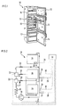
- a household refrigerator 10 is shown, the heat insulated housing 11 at its opening with hinged on the opening edge and to be opened separately Doors 12 to 14 is provided.
- Doors 12 to 14 are three in the interior of the Housing 11 arranged one above the other and by means of partitions thermally separated compartments 15 to 17 different temperature closable from which the overhead compartment lockable with the door 12 as a freezer compartment, the middle one Compartment 16, to which the door 13 is assigned, serves as a normal cooling compartment, while the underlying compartment 17 is designed as a cellar compartment and can be closed with the door 14.
- the different temperature in the individual compartments 12 to 14 is further increased refrigeration system explained in more detail below.
- the refrigeration system 18 used to cool the compartments 15 to 17 is the has an evaporator system connected to one another by refrigerant lines, equipped with a single refrigerant compressor 19.
- the refrigerant compressor 19 a condenser 20 is connected downstream on the pressure side, for example on that of the Opening of the housing 11 facing away from the rear is arranged.
- the condenser 20 connects to a dryer cartridge 21, the output of which connects to the input a first valve unit 22 is connected.
- One of the outputs of the first valve unit 22 is connected in series with the input of a second similar valve unit 22 forming between these two, fluidically connected.
- valve units 22 Due to the still free outputs of the arranged in series to each other, as are electromagnetically operated 3/2-way valves formed valve units 22 three different refrigeration circuits I, II and III formed, which can be charged with refrigerant are, the valve units 22, which are part of the refrigerant circuits I, II and III are, as control elements for the refrigerant supply to the respective refrigerant circuit serve and those arriving from the condenser 20 via the dryer cartridge 21 Divert the refrigerant flow into one of the circuits.
- Each of the valve unit outputs 22, which represent the entrance to the refrigerant circuits is one downstream spiral-shaped throttle member 23 designed as a capillary tube.
- the evaporator 24 which is arranged only in the refrigeration circuit I, with the highest Refrigeration capacity and the freezer compartment 12 is assigned.
- Each of the refrigerant circuits I to III passes through the freezer evaporator 24, the Via a refrigerant line, not specified, on the suction side to the compressor 19 connected and, if necessary, when there is a need for cold in the freezer compartment 15, alone can be acted upon with refrigerant via the refrigerant circuit I, while both the evaporator 25 in the normal cooling compartment 16 and that in the basement compartment 17, each in Series connection in front of the evaporator 24, via the refrigerant circuits II and III can be acted upon with liquid refrigerant, so that the freezer compartment 15 is always cooled becomes.
- the cooling requirement in compartments 15 and 16 is determined via the room air Temperature sensor 27 in the form of air sensors and in the freezer 14 via one the surface of the evaporator 24 arranged sensor 28 determined. Their signals are fed via signal lines 29 to and from a controller arrangement 30 evaluated.
- the controller arrangement 30 controls in dependence on the sensor signals electrical connection lines 31 both switching the refrigerant compressor on and off 19 and the valve position of the valve units 22, whichever the refrigerant circuits should be charged with refrigerant.
- Controller arrangement 30 is also controlled by electric lines 32, fans 33, one of which is arranged in the normal refrigerator compartment 16 and the other in the basement compartment 17 and there to reduce the temperature stratification both in cooling mode serve as well in defrost operation, with their arrangement of the by the cooling capacity convection current generated by the respective evaporator is supported.
- temperature sensors are provided, which the defrosting process after reaching terminate a predetermined temperature threshold.
Description
- Fig. 1
- Ein 3 Temperaturen-Haushalts-Kühlgerät, dessen thermisch voneinander getrennte Fächer unterschiedlicher Temperatur mit separaten Türen verschließbar sind, in räumlicher Darstellung von vorne und
- Fig. 2
- in vereinfachter, schematischer Darstellung, die zur Aufrechterhaltung der Temperatur in den Fächern des 3-Temperaturen-Kühlgeräts eingesetzte Kälteanlage, mit ihren symbolisch dargestellten Elementen für die Temperaturregelung der Fächer.
Claims (5)
- Kühlgerät, (10), insbesondere Mehrtemperaturen-Kühlgerät, mit einer Kältemaschine (18) und einem wärmeisolierten Gehäuse (11), in welchem ein durch Kältemittelleitungen miteinander verbundenes Verdampfersystem angeordnet ist, dessen das System bildende Verdampfer (24, 25, 26) einzeln in voneinander thermisch getrennten Fächern (15, 16, 17) angeordnet sind, deren Temperatur durch eine die Kältemittelzufuhr zu den jeweiligen Verdampfern (24, 25, 26) über eine Ventileinheit (22) steuernde Regleranordnung (30) beeinflussbar ist, wobei die Notwendigkeit der Kältemittelzufuhr über Temperaturfühler (27, 28) in den Fächern (15, 16, 17) an die Regleranordnung (30) signalisiert ist, wobei zumindest drei Fächer (15, 16, 17) mit den Ihnen zugeordneten Verdampfern (24, 25, 26) und diesen zu deren Steuerung vorgeschalteten Ventileinheiten (22) vorgesehen sind und das Fach (15) mit der größten Kälteleistung im Bedarfsfall allein für sich mit Kältemittel beaufschlagbar ist, während jedes der anderen Fächer (16, 17) im Bedarfsfall, jeweils in Reihenschaltung vor dem Fach (15) mit der höchsten Kälteleistung liegend, mit Kältemittel beaufschlagbar ist, wobei die Zahl der Ventileinheiten (22) um die Zahl 1 geringer ist, als die Zahl der Verdampfer (24, 25, 26) und die Ventileinheiten (22) als elektromagnetisch betriebene 3/2-Wege-Ventile ausgebildet sind.
- Kühlgerät nach Anspruch 1, dadurch gekennzeichnet, daß die Ventileinheiten (22) in Reihenschaltung zueinander angeordnet sind.
- Kühlgerät nach einem der Ansprüche 1 oder 2, dadurch gekennzeichnet, daß die Ventileinheiten (22) unabhängig voneinander von einem die Temperaturen in den einzelnen Fächern (15, 16, 17) auswertenden Regler (30) gesteuert sind, wobei die Temperaturen von Temperaturfühlern (27, 28) erfaßt und an den Regler (30) signalisiert werden.
- Kühlgerät nach Anspruch 1, dadurch gekennzeichnet, daß außer in dem Fach (15) mit der größten Kälteleistung in jedem der anderen Fächer (16, 17) ein Ventilator (33) angeordnet ist, der die Luft in diesen Fächern (16, 17) sowohl im Kühlals auch im Abtaubetrieb, den durch die Kälteleistung der jeweiligen Verdampfer (25, 26) erzeugten Konvektionsstrom unterstützend, zwangsweise umwälzt.
- Kühlgerät nach Anspruch 1, dadurch gekennzeichnet, daß außer in dem Fach (15) mit der größten Kälteleistung in jedem der andern Fächer (16, 17) zwei Temperaturfühler vorgesehen sind, von denen einer als Luftfühler (27) ausgebildet ist und der andere an den Oberflächen der Verdampfer (25, 26) angeordnet ist.
Applications Claiming Priority (2)
| Application Number | Priority Date | Filing Date | Title |
|---|---|---|---|
| DE19924242776 DE4242776A1 (de) | 1992-12-17 | 1992-12-17 | Kühlgerät, insbesondere Mehrtemperaturen-Kühlgerät |
| DE4242776 | 1992-12-17 |
Publications (3)
| Publication Number | Publication Date |
|---|---|
| EP0602379A2 EP0602379A2 (de) | 1994-06-22 |
| EP0602379A3 EP0602379A3 (en) | 1994-07-27 |
| EP0602379B1 true EP0602379B1 (de) | 2002-03-20 |
Family
ID=6475650
Family Applications (1)
| Application Number | Title | Priority Date | Filing Date |
|---|---|---|---|
| EP93117985A Expired - Lifetime EP0602379B1 (de) | 1992-12-17 | 1993-11-05 | Kühlgerät, insbesondere Mehrtemperaturen-Kühlgerät |
Country Status (5)
| Country | Link |
|---|---|
| EP (1) | EP0602379B1 (de) |
| DE (2) | DE4242776A1 (de) |
| DK (1) | DK0602379T3 (de) |
| ES (1) | ES2173880T3 (de) |
| TR (1) | TR27444A (de) |
Families Citing this family (11)
| Publication number | Priority date | Publication date | Assignee | Title |
|---|---|---|---|---|
| RU2137064C1 (ru) * | 1994-11-11 | 1999-09-10 | Самсунг Электроникс Ко., Лтд. | Холодильник с высокоэффективным холодильным циклом с несколькими испарителями (н.и.цикл) и способ управления этим холодильником |
| DE19509571A1 (de) * | 1995-03-16 | 1996-09-19 | Bosch Siemens Hausgeraete | Verdampfer, insbesondere für kompressorbetriebene Haushalt-Kältegeräte |
| DE19547744A1 (de) * | 1995-12-20 | 1997-06-26 | Bosch Siemens Hausgeraete | Kältegerät |
| US5896753A (en) * | 1996-10-18 | 1999-04-27 | Lg Electronics Inc. | Freezing cycle apparatus having quick freezing and thawing functions |
| DE19818288B4 (de) * | 1998-04-23 | 2009-04-30 | BSH Bosch und Siemens Hausgeräte GmbH | Kühlgerät |
| JP4028688B2 (ja) * | 2001-03-21 | 2007-12-26 | 株式会社東芝 | 冷蔵庫 |
| DE10140005A1 (de) | 2001-08-16 | 2003-02-27 | Bsh Bosch Siemens Hausgeraete | Kombinations-Kältegerät und Verdampferanordnung dafür |
| DE102005057149A1 (de) | 2005-11-30 | 2007-06-06 | BSH Bosch und Siemens Hausgeräte GmbH | Verfahren zum Betreiben eines Kühlschranks sowie Kühlschrank mit einem zeitverzögerten Einschalten des Verdichters |
| DE102007016849A1 (de) * | 2007-04-10 | 2008-10-16 | BSH Bosch und Siemens Hausgeräte GmbH | Kältegerät mit drei Temperaturzonen |
| DE202008009956U1 (de) * | 2008-04-15 | 2009-08-20 | Liebherr-Hausgeräte Lienz Gmbh | Kühl- und/oder Gefriergerät |
| DE102008047818A1 (de) * | 2008-08-22 | 2010-02-25 | Liebherr-Hausgeräte Lienz Gmbh | Kühl-und/oder Gefriergerät sowie Verfahren zum Betreiben eines Kühl-und/oder Gefriergerätes |
Family Cites Families (3)
| Publication number | Priority date | Publication date | Assignee | Title |
|---|---|---|---|---|
| JPS59164860A (ja) * | 1983-03-09 | 1984-09-18 | 株式会社東芝 | 冷蔵庫の冷凍サイクル |
| JPS59212662A (ja) * | 1983-05-18 | 1984-12-01 | 株式会社東芝 | 冷蔵庫 |
| ES2012138A6 (es) * | 1988-11-08 | 1990-03-01 | Ulgor S Coop | Mejoras introducidas en un frigorifico-congelador combinado de tres recintos independientes. |
-
1992
- 1992-12-17 DE DE19924242776 patent/DE4242776A1/de not_active Withdrawn
-
1993
- 1993-11-05 EP EP93117985A patent/EP0602379B1/de not_active Expired - Lifetime
- 1993-11-05 ES ES93117985T patent/ES2173880T3/es not_active Expired - Lifetime
- 1993-11-05 DE DE59310273T patent/DE59310273D1/de not_active Expired - Lifetime
- 1993-11-05 DK DK93117985T patent/DK0602379T3/da active
- 1993-12-15 TR TR01195/93A patent/TR27444A/xx unknown
Non-Patent Citations (1)
| Title |
|---|
| Langley, Refrigeration and Air Conditioning, 3. Auflage 1986, Seiten 336 und 352 * |
Also Published As
| Publication number | Publication date |
|---|---|
| DK0602379T3 (da) | 2002-07-08 |
| DE4242776A1 (de) | 1994-06-23 |
| ES2173880T3 (es) | 2002-11-01 |
| DE59310273D1 (de) | 2002-04-25 |
| EP0602379A2 (de) | 1994-06-22 |
| EP0602379A3 (en) | 1994-07-27 |
| TR27444A (tr) | 1995-05-24 |
Similar Documents
| Publication | Publication Date | Title |
|---|---|---|
| DE60018001T2 (de) | Kühlschrank mit zwei Verdampfern | |
| DE69911925T2 (de) | Kühlschrank mit verdampfer im kühlfach und im tiefkühlfach | |
| EP2342511B1 (de) | Haushaltskältegerät sowie haushaltskältegerät-modulanordnung | |
| DE102004014926A1 (de) | Kältegerät mit zwei Lagerfächern | |
| DE102012020111A1 (de) | Hochleistungskühlgerät mit zwei verdampfern | |
| DE112016000456B4 (de) | Kühlschrank | |
| DE102012020106A1 (de) | HOCHLEISTUNGSKÜHLGERÄT MIT VERDAMPFER AUßERHALB DES SCHRANKS | |
| DE102005060335A1 (de) | Abtaueinrichtung für einen Kühlschrank | |
| EP2218987A2 (de) | Kältegerät mit Flaschenkühlfunktion | |
| EP0602379B1 (de) | Kühlgerät, insbesondere Mehrtemperaturen-Kühlgerät | |
| DE102012020112A1 (de) | High performance refrigerator having insulated evaporator cover | |
| EP2798285B1 (de) | Haushaltskältegerät mit einem kaltlagerfach | |
| DE10204527B4 (de) | Kühlluftversorgungsvorrichtung eines Kühlschranks | |
| EP1886082A1 (de) | Kühl- und/oder gefriergerät | |
| DE69732468T2 (de) | Kühlanlage mit veränderlicher Zwangsbelüftung | |
| DE60015666T2 (de) | Haushalts-Kühlschrank mit einem Fach für schnelles Kühlen von Nahrung | |
| EP3426989A1 (de) | Kältegerät mit einem gefrierfach und einem kältemittelkreis und verfahren zum betrieb eines kältegeräts | |
| DE102012222240A1 (de) | Mehrzonen-Kältegerät | |
| DE102008044130A1 (de) | Kältegerät mit mehreren Lagerfächern | |
| EP0602371B1 (de) | Kühlgerät mit einem wärmeisolierten Gehäuse | |
| DE10300703B4 (de) | Gefriergerät und Enteisungsverfahren | |
| DE4433712A1 (de) | Kühlmöbel mit wenigstens zwei Fächern unterschiedlicher Temperatur | |
| EP2110622B1 (de) | Kühl- und/oder Gefriergerät | |
| DE102010055726A1 (de) | Kühl- und/oder Gefriergerät | |
| DE102019210540A1 (de) | Haushaltskältegerätevorrichtung |
Legal Events
| Date | Code | Title | Description |
|---|---|---|---|
| PUAI | Public reference made under article 153(3) epc to a published international application that has entered the european phase |
Free format text: ORIGINAL CODE: 0009012 |
|
| PUAL | Search report despatched |
Free format text: ORIGINAL CODE: 0009013 |
|
| AK | Designated contracting states |
Kind code of ref document: A2 Designated state(s): DE DK ES FR IT SE |
|
| AK | Designated contracting states |
Kind code of ref document: A3 Designated state(s): DE DK ES FR IT SE |
|
| 17P | Request for examination filed |
Effective date: 19950112 |
|
| 17Q | First examination report despatched |
Effective date: 19970425 |
|
| RAP1 | Party data changed (applicant data changed or rights of an application transferred) |
Owner name: BSH BOSCH UND SIEMENS HAUSGERAETE GMBH |
|
| APAB | Appeal dossier modified |
Free format text: ORIGINAL CODE: EPIDOS NOAPE |
|
| APAB | Appeal dossier modified |
Free format text: ORIGINAL CODE: EPIDOS NOAPE |
|
| APAD | Appeal reference recorded |
Free format text: ORIGINAL CODE: EPIDOS REFNE |
|
| APCB | Communication from the board of appeal sent |
Free format text: ORIGINAL CODE: EPIDOS OBAPE |
|
| APCB | Communication from the board of appeal sent |
Free format text: ORIGINAL CODE: EPIDOS OBAPE |
|
| APAB | Appeal dossier modified |
Free format text: ORIGINAL CODE: EPIDOS NOAPE |
|
| GRAG | Despatch of communication of intention to grant |
Free format text: ORIGINAL CODE: EPIDOS AGRA |
|
| GRAH | Despatch of communication of intention to grant a patent |
Free format text: ORIGINAL CODE: EPIDOS IGRA |
|
| GRAH | Despatch of communication of intention to grant a patent |
Free format text: ORIGINAL CODE: EPIDOS IGRA |
|
| GRAA | (expected) grant |
Free format text: ORIGINAL CODE: 0009210 |
|
| AK | Designated contracting states |
Kind code of ref document: B1 Designated state(s): DE DK ES FR IT SE |
|
| REF | Corresponds to: |
Ref document number: 59310273 Country of ref document: DE Date of ref document: 20020425 |
|
| REG | Reference to a national code |
Ref country code: DK Ref legal event code: T3 |
|
| ET | Fr: translation filed | ||
| REG | Reference to a national code |
Ref country code: ES Ref legal event code: FG2A Ref document number: 2173880 Country of ref document: ES Kind code of ref document: T3 |
|
| PLBE | No opposition filed within time limit |
Free format text: ORIGINAL CODE: 0009261 |
|
| STAA | Information on the status of an ep patent application or granted ep patent |
Free format text: STATUS: NO OPPOSITION FILED WITHIN TIME LIMIT |
|
| 26N | No opposition filed |
Effective date: 20021223 |
|
| PGFP | Annual fee paid to national office [announced via postgrant information from national office to epo] |
Ref country code: DK Payment date: 20031121 Year of fee payment: 11 |
|
| PGFP | Annual fee paid to national office [announced via postgrant information from national office to epo] |
Ref country code: SE Payment date: 20031124 Year of fee payment: 11 |
|
| PG25 | Lapsed in a contracting state [announced via postgrant information from national office to epo] |
Ref country code: SE Free format text: LAPSE BECAUSE OF NON-PAYMENT OF DUE FEES Effective date: 20041106 |
|
| PG25 | Lapsed in a contracting state [announced via postgrant information from national office to epo] |
Ref country code: DK Free format text: LAPSE BECAUSE OF NON-PAYMENT OF DUE FEES Effective date: 20041130 |
|
| REG | Reference to a national code |
Ref country code: DK Ref legal event code: EBP |
|
| EUG | Se: european patent has lapsed | ||
| APAH | Appeal reference modified |
Free format text: ORIGINAL CODE: EPIDOSCREFNO |
|
| PGFP | Annual fee paid to national office [announced via postgrant information from national office to epo] |
Ref country code: IT Payment date: 20101124 Year of fee payment: 18 |
|
| PGFP | Annual fee paid to national office [announced via postgrant information from national office to epo] |
Ref country code: ES Payment date: 20111123 Year of fee payment: 19 Ref country code: FR Payment date: 20111125 Year of fee payment: 19 |
|
| REG | Reference to a national code |
Ref country code: DE Ref legal event code: R084 Ref document number: 59310273 Country of ref document: DE Effective date: 20120207 |
|
| PGFP | Annual fee paid to national office [announced via postgrant information from national office to epo] |
Ref country code: DE Payment date: 20121130 Year of fee payment: 20 |
|
| REG | Reference to a national code |
Ref country code: FR Ref legal event code: ST Effective date: 20130731 |
|
| PG25 | Lapsed in a contracting state [announced via postgrant information from national office to epo] |
Ref country code: IT Free format text: LAPSE BECAUSE OF NON-PAYMENT OF DUE FEES Effective date: 20121105 |
|
| REG | Reference to a national code |
Ref country code: DE Ref legal event code: R071 Ref document number: 59310273 Country of ref document: DE |
|
| PG25 | Lapsed in a contracting state [announced via postgrant information from national office to epo] |
Ref country code: FR Free format text: LAPSE BECAUSE OF NON-PAYMENT OF DUE FEES Effective date: 20121130 |
|
| PG25 | Lapsed in a contracting state [announced via postgrant information from national office to epo] |
Ref country code: DE Free format text: LAPSE BECAUSE OF EXPIRATION OF PROTECTION Effective date: 20131106 |
|
| REG | Reference to a national code |
Ref country code: ES Ref legal event code: FD2A Effective date: 20140305 |
|
| PG25 | Lapsed in a contracting state [announced via postgrant information from national office to epo] |
Ref country code: ES Free format text: LAPSE BECAUSE OF NON-PAYMENT OF DUE FEES Effective date: 20121106 |