EP0601812A2 - Procédé anatomique - Google Patents
Procédé anatomique Download PDFInfo
- Publication number
- EP0601812A2 EP0601812A2 EP93309735A EP93309735A EP0601812A2 EP 0601812 A2 EP0601812 A2 EP 0601812A2 EP 93309735 A EP93309735 A EP 93309735A EP 93309735 A EP93309735 A EP 93309735A EP 0601812 A2 EP0601812 A2 EP 0601812A2
- Authority
- EP
- European Patent Office
- Prior art keywords
- diaphragm
- cutting tool
- tool
- cutting
- carcass
- Prior art date
- Legal status (The legal status is an assumption and is not a legal conclusion. Google has not performed a legal analysis and makes no representation as to the accuracy of the status listed.)
- Withdrawn
Links
Images


Classifications
-
- A—HUMAN NECESSITIES
- A22—BUTCHERING; MEAT TREATMENT; PROCESSING POULTRY OR FISH
- A22B—SLAUGHTERING
- A22B5/00—Accessories for use during or after slaughtering
- A22B5/0005—Eviscerating devices, e.g. removing rectum, anus, intestines, brain tissue, hypophysis
Definitions
- This invention relates to evisceration that is, both processes and equipment for the removal of the internal organs of an animal prior to butchery of the carcass.
- the conventional evisceration process used for pigs in the United Kingdom involves hanging the pig head down, removing the sex organs, loosening the rectum, splitting between the hams, opening the belly, splitting the sternum, pulling the rectum and anal passage away from the spine whilst severing the connective tissue so as to progressively free the entrails from the caudal end of the spine towards the diaphragm, cutting either side of the diaphragm, freeing the organs as far as the throat, pulling the organs out, splitting the carcass into two sides, and severing the head.
- organs As the organs are disconnected from the spine, they are generally further divided into organ sub-groups consisting of sex organs (male), intestines with stomach, liver with lungs and trachea. Other organs may also be removed individually. This process is carried out manually, and requires skilled personnel.
- An object of the present invention is to provide an improved evisceration process and equipment, especially for severing the connective tissue connecting the internal organs to the spine, for cutting the diaphragm, and for removal of organs from the carcass cavity.
- the invention consists in an automated evisceration process in which a connective tissue cutting tool is guided along the spine of a carcass from the caudal end towards the diaphragm to sever the connective tissue holding internal organs to the spine, characterised in that the cutting tool is guided along a predetermined path which is scaled according to at least one an external dimension of the carcass.
- the external dimension of the carcass employed is its length, possibly as determined by a vision system, and other carcass measurements such as weight or fat may be used as supplementary scaling parameters
- the cutting tool is resiliently loaded against the spine so that it can ride over undulations in the shape of the spine.
- sensor means may be provided to sense the contact force between the cutting tool and the spine and to produce a force feedback signal to modify said predetermined path of the cutting tool whilst the tool is following said path.
- the invention consists in an automated evisceration process in which a connective tissue cutting tool is guided along the spine of a carcass from the caudal end towards the diaphragm to sever the connective tissue holding internal organs to the spine, characterised in that the cutting tool incorporates sensor means to sense the presence of the diaphragm and to trigger recording of the position of the diaphragm for subsequent use in cutting the diaphragm.
- the invention consists in an automated evisceration process in which a connective tissue cutting tool is guided along the spine of a carcass from the caudal end towards the diaphragm to sever the connective tissue holding internal organs to the spine, characterised in that the cutting tool incorporates sensor means to sense the presence of the diaphragm and thereby trigger predetermined controlled movements of the cutting tool to assist it in passing through an opening which it forms in the diaphragm.
- the cutting tool cuts through the diaphragm, and continues to sever the connective tissue for a predetermined distance along the spine beyond the diaphragm before being withdrawn through the cut in the diaphragm.
- a diaphragm cutting tool is inserted into the cut before being moved around the edge of the diaphragm to cut the same, the diaphragm cutting tool being located in said cut by reference to the recorded position of the diaphragm.
- the invention consists in a connective tissue cutting tool comprising cutting means and a pair of guide fingers that project forwardly and diverge outwardly away from the cutting means so as to gather tissue in towards the cutting means in use.
- the cutting means comprises a rotating blade that performs a shearing action.
- sensor means is incorporated in the cutting tool to sense the presence of a surface, such as a diaphragm.
- a base skid is provided to assist movement of the cutting tool over the surface of a carcass when the tool is in use.
- the invention consists in a diaphragm cutting tool comprising an elongate cutting blade and a holder from which the blade extends, a guard supported by the holder so as to extend laterally from the blade to space the blade away from a carcass wall when cutting a diaphragm attached to the wall.
- the invention consists in an automated butchery process in which a diaphragm is cut from a carcass wall by inserting an elongate cutting blade through an aperture in the diaphragm and moving the blade around the periphery of the diaphragm, characterised in that a guard is associated with the blade which extends laterally from the blade and cooperates with the carcass wall to space the blade away from the carcass wall.
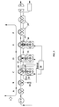
- the evisceration process takes place in a number of stages at a succession of work stations A to F as shown in Figure 1.
- Pig carcasses are conveyed in support fixtures 1 between these respective stations for processing.
- Each pig carcass, before being loaded into a support fixture 1, is cleaned and dehaired, has a rectum plug 4 inserted, has sex organs removed (if appropriate) has the rectum 2 loosened from between the hams, is split between the hams and has the pubic bone separated, and is split down the belly and sternum.
- Each carcass is loaded head down into a support fixture 1 at a loading station A as shown in Figures 14 and 15.
- the hind legs are spread apart by a standard gambrel.
- the rib-cage is opened out and the carcass pulled back against spine supports 5 in the fixture by a pair of sternum hooks 6 which are each hooked over the edge of a respective half of the sternum to pull them apart through a tensioning mechanism 7 connected to the hooks by wires 8.
- Each hook 6 engages the split edge of the respective sternum half and is pulled upwards into engagement into the cranial side of the diaphragm 9 where it joins the sternurn.
- the rectum plug 4 is then fixed to a holding mechanism located on the fixture.
- the fixture 1 is then moved on to a scanning station B where a two dimensional visual scanner 10 assesses particular features of the carcass relevant to the subsequent butchery processes. These features comprise the length of the carcass, the location of the 'V' formed between the rectum 2 and the caudal vertebrae 3, and the positions of the sternum hooks 6.
- the fixture 1 is then moved on to a connective tissue cutting station C where a connective tissue cutting tool 12 mounted at the end of a robot arm 11, is moved under the control of a controller 14, down the spine of the carcass within the cavity to free internal organs from the spine.
- a connective tissue cutting tool 12 mounted at the end of a robot arm 11, is moved under the control of a controller 14, down the spine of the carcass within the cavity to free internal organs from the spine.
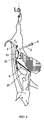
- Figure 2 which shows the path of the cutting tool 12, marked by arrows.
- the cut begins at the position of the 'V' between the rectum 2 and the caudal vertebrae 3 as identified by the scanner 10, and passes over the kidneys 13 and along the spine as far as the diaphragm 9. Once past the kidneys, the tool is tilted forwards in towards the spine and then backwards so that the tool engages the spine.
- the path of the cutting tool 12 and its orientation along this cutting path is based on an average or typical path as determined by the measurement of a plurality of carcasses, and this average path is scaled according to the length of the carcass determined by the scanner 10.
- An algorithm corresponding to this average path is stored in the controller 14, and is scaled by the carcass length measurement supplied to the controller by the scanner 10.
- the robot arm 11 incorporates resilient means 15 which allows the cutting tool 12 to be loaded against the spine so that it can ride over undulations of the spine and kidneys 13 without damaging them. Furthermore, a transducer 16 is provided to sense the contact force between the cutting tool 12 and the spine and produce a corresponding force feedback signal which is supplied to the controller 14. This force feedback signal indicates to the controller when the cutting tool 12 is in contact with the spine in the start position and triggers movement of the cutting tool 12 along its predetermined cutting path.
- the force feedback signal from the transducer 16 also serves to modify said predetermined cutting path whilst the tool follows said path. That is, the controller 14 monitors the force feedback signal for variations consistent with a mismatch of the shape of the carcass with said predetermined path, and adjusts said predetermined path accordingly.
- This adjustment process is necessarily a predictive process to match said predetermined path to the particular carcass, because the speed of movement of the cutting tool along this path prevents instantaneous path matching at the actual location of the cutting tool at any moment in time.
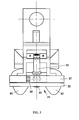
- the cutting tool 12 is illustrated in Figure 3 to 5 and comprises a base 17 on top of which is mounted a rotary cutting blade 18 which is inclined downwards in the forward direction so as to overhang the leading edge of the base.
- the blade 18 is carried at the lower end of the drive shaft 19 supported by a bracket 20 above the base 17, and a pneumatic motor 21 is mounted on the base 17 to drive the shaft 19.
- a skid plate 22 is mounted on the underside of the base 17 so that it is longitudinally slidable relative to the base in the forwards and rearwards directions.
- a pneumatic spring 23 is connected between the skid plate and base on the underside of the base so as to urge the skid plate 22 to a forwardmost position.
- the spring 23 extends forwards and downwards and is connected by horizontal pivot pins 24,25 at its opposite ends to the skid plate 22 and base 17, respectively.
- rearwards movement of the skid plate 22 causes the spring 23 to contract and pivot rearwards about the upper rear pivot pin 25 as shown in broken outline in Figure 4.
- the underside of the skid plate 22 is formed with downward projections 40 either side of the cutting blade 18 so as to form a recess 41 therebetween to accommodate the shape of the spine and kidneys 13, thereby facilitating movement of the cutting tool and protecting the carcass against damage.
- the forward end of the skid plate 22 is shaped, as shown in Figure 3 and 4, so that it has two forwardly extending guide fingers 26, one each side of the cutting blade 18. These guide fingers 26 have inner guide surfaces 27 which diverge outwardly away from the cutting blade 18 so as to gather tissue lying in their path and feed it towards the cutting blade when the skid plate is in its normal forwardmost position.
- the guide fingers 26 engage the diaphragm and are pushed rearwards of the base 17 as the tool continues to be moved forward by the robot arm 11. This rearwards movement of the guide fingers 26 exposes a wider section of the leading edge of the blade 18 which therefore makes a widening cut in the diaphragm until the full width of the leading end of the cutting tool including the guide fingers 26 are able to pass through the cut made in the diaphragm.
- the skid plate 22 is then extended to its forwardmost position again by the spring 23, and the cutting tool continues along its predetermined path, following the spine and cutting behind the aorta. Typically, the tool continues for a distance of approximately 200 m.m. beyond the diaphragm before it is stopped and withdrawn through the cut in the diaphragm.
- a microswitch 28 is mounted on the base 17 to cooperate with a peg 50 on the skid plate 22 when the latter moves rearwards, thereby sensing when the tool engages the diaphragm 9, and producing a diaphragm position signal which is passed to the controller 14 for subsequent use as described hereafter.
- the fixture 1 is then moved on to a diaphragm side cutting station D where a diaphragm cutting tool 30 is operational.
- This tool is mounted at the end of a robot arm 31 and performs a predetermined cutting operation around the outer periphery of the diaphragm 9 where it joins the rib cage.
- the tool illustrated in Figure 9 comprises an elongate knife blade 32 supported in a holder 33 at one end which incorporates pneumatic drive means that causes the blade to reciprocate in use.
- a resilient plastics non-cutting blade 34 is carried at the end of the knife blade 32 so that it lies substantially in the cutting plane of the knife blade 32 and extends beyond the end of the knife blade 32. The purpose of this resilient non-cutting blade 34 will be understood from the following description.
- the blades 32,34 of the diaphragm cutting tool 30 are inserted through the cut made in the diaphragm by the connective tissue cutting tool 12, this position having been recorded by the controller 14 when the tool 12 engaged the diaphragm. These blades 32,34 are inserted along the length of the spine to one side of the aorta.
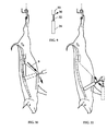
- the drive of the knife blade is activated and the tool rotated about its tip, as shown in Figure 10, to cut around the periphery of the diaphragm 9 to one side of the spine.
- the whole tool is moved bodily downwards passing the resilient non-cutting blade 34 between the rib cage and the lungs to sever any pleuritic adhesions between the lungs and rib cage.
- the tool is then swung downwards about the holder 33, as shown in Figure 11, causing the flexible non-cutting blade 34 to make a final sweep through the carcass cavity and exit at the neck.
- the flexible non-cutting blade 34 flexes to follow the curved inner surface of the rib cage, and is wide enough to move over the undulations in the surface, and is long enough to pass over all of those surfaces requiring severing of pleuritic adhesions.
- the same diaphragm cutting tool 30 can be used in two separate operations to cut the diaphragm on both sides of the spine, or two similar tools can be used simultaneously on opposite sides of the spine.
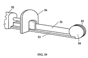
- FIG. 18 and 19 An alternative diaphragm cutting tool is illustrated in Figure 18 and 19 comprises an elongate knife blade 51 supported in a holder 52 at one end which incorporates pneumatic drive means to reciprocate the blade.
- a support bar 53 extends from the holder 52 alongside the blade 51 and carries at its free end a rounded nose 54 which is disc-shaped in the plane of the blade and is formed with a central slot 55 that receives the end of the blade.
- a D-shaped hilt guard 56 is mounted on the support bar 53 and the blade 51 projects through it.
- the flat 57 of the hilt guard is aligned with the back of the support bar 53 so that the blade 51 lies in the centre plane of the D-shape.
- the rounded periphery of the hilt guard then lies on a substantially constant radius from the cutting edge of the blade.
- the blade 51 and support bar 53 are inserted through the cut in the diaphragm 9.
- the rounded nose 54 serves to protect the tool against snagging on the diaphragm or other internal tissues or organs.
- the hilt guard 56 is then held against the rib cage, and with this contact maintained, the whole tool is moved around the inside of the rib-cage from the spine towards the sternum, cutting the periphery of the diaphragm of the diaphragm in the process.
- the hilt guard 56 spaces the cutting edge of the blade 51 away from the rib cage, and thus some of the diaphragm 9 is left attached to the carcass. Because this diaphragm is composed of muscle or meat, the value of the carcass is enhanced by retaining some of it.
- the movement of the diaphragm cutting tool is, like before, controlled by the robot arm 31 and controller 14.
- a force feedback transducer 57 is incorporated in the robot arm 31 so that the tool can be moved on a path to maintain a constant contact force between the hilt guard 56 and the rib cage.
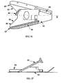
- Figure 20 illustrates how the diaphragm cutting tool is supported in a substantially vertical orientation during the cutting operation so that the blade 51 maintains an angle less than 45 degrees with the diaphragm 9 and exits around and away from the sternum.
- the fixture 1 is now moved on to an organ removal station E where a rotary brush 35 cleans the inside of the carcass and a pair of clamp bars 36 grasp the lungs 37 and pull the organs free from the carcass.
- the brush 35 is adapted to fit the full width of the carcass cavity and clean all surfaces, the brush having stiff nylon bristles which flex to conform to the shape of the internal surfaces.
- the brush is moved downwards through the carcass cavity in a single motion by a robot arm 38.
- the sense of rotation of the brush is such that it helps to push the organs out of the carcass, as shown in Figure 12.
- the clamp bars 36 are supported on the robot arm 38 with the brush 35 and are aligned vertically to pass close to the sternum and between the fore-legs of the carcass.
- the spacing between the clamp bars is sufficient to receive the lungs 37 between them.
- a pneumatic actuator serves to close the clamp bars together to grasp the lungs, and the bars and brush are then moved downwards and away from the carcass at an angle of approximately 45 degrees to the horizontal to pull the trachea and oesophagus from the neck cavity and deposit the complete set of intestines in a collection vessel 39.
- the fixture 1 is then moved on to an unloading station F where the carcass is removed from the fixture 1 together with the intestines.
- a head cropper is then used to cut the head off the carcass, thereby finally freeing the intestines from the carcass.
- the cutting tool of Figures 3 to 5 may be replaced by the cutting tool illustrated in Figures 16 and 17 comprising a skid plate 42 on which is mounted cutting means 43.
- a pair of guide fingers 44, one each side of the cutting means, project forwardly and have inner guide surfaces 45 which diverge outwardly away from the cutting means so as to gather the tissue lying in their path and feed it towards the cutting means.
- the cutting means 43 comprises a pair of counter-reciprocating toothed blades which perform a scissoring action.
- the blades are driven by a pneumatic motor.
- the blades are inclined downwards relative to the skid plate 42, as shown in Figure 17, for a more effective cutting action.
- Pneumatic sensor means is also incorporated in the cutting tool to sense when the tool is close to the diaphragm 9.
- the sensor means comprises an air passage 46 in each guide finger 44 which opens at a sensing port 47 at the tip of the finger.
- An air supply 48 is connected to the passages 46 so that air flows from each sensing port 47 and is disturbed by the proximity of the diaphragm 9, causing a back-pressure at the air supply which is detected by pressure sensor.
- the cutting tool 12 is moved down the spine along a predetermined path as already described above. However, a short distance beyond the kidneys 13, the tips of the guide fingers 44 approach close to the diaphragm, triggering the pneumatic sensor means to stop the tool and record the stop position. At this point, the guide fingers 44 straddle the central ridge of the diaphragm 9 and the blades 43 engage it to form a small cut. This cut is widened by the weight of the intestines hanging forwards. The cutting tool now resumes its downwards movement passing through the cut opened in the diaphragm 9.
- the tool performs a programmed movement comprising tilting sideways about a horizontal axis, first one way then the other, as shown in Figures 6 and 7, so as to ensure that each of the guide fingers 44 in turn passes through the cut.
- the cutting tool can then continue to follow the spine closely to the end of the cut path.
Landscapes
- Health & Medical Sciences (AREA)
- General Health & Medical Sciences (AREA)
- Neurosurgery (AREA)
- Life Sciences & Earth Sciences (AREA)
- Engineering & Computer Science (AREA)
- Food Science & Technology (AREA)
- Surgical Instruments (AREA)
Applications Claiming Priority (2)
| Application Number | Priority Date | Filing Date | Title |
|---|---|---|---|
| GB9225321 | 1992-12-03 | ||
| GB929225321A GB9225321D0 (en) | 1992-12-03 | 1992-12-03 | Evisceration |
Publications (2)
| Publication Number | Publication Date |
|---|---|
| EP0601812A2 true EP0601812A2 (fr) | 1994-06-15 |
| EP0601812A3 EP0601812A3 (en) | 1994-09-14 |
Family
ID=10726082
Family Applications (1)
| Application Number | Title | Priority Date | Filing Date |
|---|---|---|---|
| EP9393309735A Withdrawn EP0601812A3 (en) | 1992-12-03 | 1993-12-03 | An anatomical process. |
Country Status (2)
| Country | Link |
|---|---|
| EP (1) | EP0601812A3 (fr) |
| GB (2) | GB9225321D0 (fr) |
Cited By (12)
| Publication number | Priority date | Publication date | Assignee | Title |
|---|---|---|---|---|
| WO1996036231A1 (fr) * | 1995-05-15 | 1996-11-21 | Swift-Eckrich, Inc. | Procede permettant de reduire la dispersion de matieres fecales et une contamination par ces matieres durant le traitement de la viande |
| NL1000877C2 (nl) * | 1995-07-24 | 1997-01-28 | Stork Rms Bv | Werkwijze en inrichting voor het losmaken van ingewanden. |
| EP0856257A2 (fr) | 1997-02-03 | 1998-08-05 | Slagteriernes Forskningsinstitut | Procédé et dispositif pour l'éviscération de carcasses animales et procédé et dispositif de mesure pour déterminer le niveau d'une partie anatomique d'une carcasse animale |
| EP0879558A2 (fr) | 1997-05-06 | 1998-11-25 | Slagteriernes Forskningsinstitut | Procédé et dispositif d'évisceration des carcasses animales |
| NL1011287C2 (nl) * | 1999-02-12 | 2000-08-15 | Stork Mps Bv | Werkwijze en inrichting voor het losmaken van het veteind van een karkas. |
| US6174229B1 (en) | 1998-01-20 | 2001-01-16 | Slagteriernes Forskningsinstitut | Method and device for evisceration of carcasses |
| EP1135989A2 (fr) * | 2000-03-22 | 2001-09-26 | Slagteriernes Forskningsinstitut | Procédé et outils pour séparer mécaniquement un organe de la cavité thoracique ou abdominale d'une carcasse |
| EP1188381A1 (fr) * | 2000-09-15 | 2002-03-20 | Slagteriernes Forskningsinstitut | Appareil et procédé pour séparer un organe d'un ensemble d'organes d'une carcasse |
| EP1245155A1 (fr) * | 2001-03-23 | 2002-10-02 | Slagteriernes Forskningsinstitut | Appareil, outil, et procédé pour détacher le coeur et les poumons d'une carcasse |
| WO2005094593A3 (fr) * | 2004-04-02 | 2005-12-29 | Slagteriernes Forskningsinst | Appareil, procede et couteau pour detacher un ensemble de fressure a partir d'une carcasse |
| DE202005004098U1 (de) * | 2005-03-15 | 2006-08-03 | Schmid & Wezel Gmbh & Co | Werkzeugeinrichtung zum Abtrennen von Teilen von Schlachttieren |
| DE202005016074U1 (de) * | 2005-10-11 | 2007-02-22 | Banss Schlacht- und Fördertechnik GmbH | Anordnung zum Abtrennen von Körperteilen von Schlachttieren |
Citations (2)
| Publication number | Priority date | Publication date | Assignee | Title |
|---|---|---|---|---|
| AU6790690A (en) * | 1989-12-07 | 1991-06-13 | Meat Industry Research Institute of New Zealand Incorporated, The | A method and means of removing and handling animal viscera |
| WO1992022210A1 (fr) * | 1991-06-18 | 1992-12-23 | Commonwealth Scientific & Industrial Research Organisation | Evisceration d'animaux |
Family Cites Families (2)
| Publication number | Priority date | Publication date | Assignee | Title |
|---|---|---|---|---|
| DK159579C (da) * | 1975-01-10 | 1991-04-29 | Ataliers De Const Mecaniques L | Apparat til deling af lodret ophaengte kroppe af slagtedyr |
| FR2324238A1 (fr) * | 1975-06-10 | 1977-04-15 | Anvar | Procede d'evisceration automatique de carcasses d'animaux de boucherie |
-
1992
- 1992-12-03 GB GB929225321A patent/GB9225321D0/en active Pending
-
1993
- 1993-12-03 GB GB9324897A patent/GB2273036A/en not_active Withdrawn
- 1993-12-03 EP EP9393309735A patent/EP0601812A3/en not_active Withdrawn
Patent Citations (2)
| Publication number | Priority date | Publication date | Assignee | Title |
|---|---|---|---|---|
| AU6790690A (en) * | 1989-12-07 | 1991-06-13 | Meat Industry Research Institute of New Zealand Incorporated, The | A method and means of removing and handling animal viscera |
| WO1992022210A1 (fr) * | 1991-06-18 | 1992-12-23 | Commonwealth Scientific & Industrial Research Organisation | Evisceration d'animaux |
Cited By (22)
| Publication number | Priority date | Publication date | Assignee | Title |
|---|---|---|---|---|
| WO1996036231A1 (fr) * | 1995-05-15 | 1996-11-21 | Swift-Eckrich, Inc. | Procede permettant de reduire la dispersion de matieres fecales et une contamination par ces matieres durant le traitement de la viande |
| NL1000877C2 (nl) * | 1995-07-24 | 1997-01-28 | Stork Rms Bv | Werkwijze en inrichting voor het losmaken van ingewanden. |
| EP0755628A1 (fr) * | 1995-07-24 | 1997-01-29 | Stork R.M.S. B.V. | Procédé et dispositif pour enlever les intestins |
| US5820452A (en) * | 1995-07-24 | 1998-10-13 | Stork R.M.S. B.V. | Method and device for releasing intestines |
| EP0856257A2 (fr) | 1997-02-03 | 1998-08-05 | Slagteriernes Forskningsinstitut | Procédé et dispositif pour l'éviscération de carcasses animales et procédé et dispositif de mesure pour déterminer le niveau d'une partie anatomique d'une carcasse animale |
| EP0856257A3 (fr) * | 1997-02-03 | 1999-12-29 | Slagteriernes Forskningsinstitut | Procédé et dispositif pour l'éviscération de carcasses animales et procédé et dispositif de mesure pour déterminer le niveau d'une partie anatomique d'une carcasse animale |
| EP0879558A2 (fr) | 1997-05-06 | 1998-11-25 | Slagteriernes Forskningsinstitut | Procédé et dispositif d'évisceration des carcasses animales |
| EP0879558A3 (fr) * | 1997-05-06 | 1999-12-29 | Slagteriernes Forskningsinstitut | Procédé et dispositif d'évisceration des carcasses animales |
| US6174229B1 (en) | 1998-01-20 | 2001-01-16 | Slagteriernes Forskningsinstitut | Method and device for evisceration of carcasses |
| US6364758B1 (en) | 1998-01-20 | 2002-04-02 | Slagteriernes Forskningsinstitut | Method and device for evisceration of carcasses |
| NL1011287C2 (nl) * | 1999-02-12 | 2000-08-15 | Stork Mps Bv | Werkwijze en inrichting voor het losmaken van het veteind van een karkas. |
| EP1027829A1 (fr) * | 1999-02-12 | 2000-08-16 | Stork MPS B.V. | Dispositif et procédé à détacher le rectum d'une carcasse,et dispositif de découpage d'orifice anal |
| EP1260141A3 (fr) * | 1999-02-12 | 2003-01-02 | Stork MPS B.V. | Dispositif de découpage d'orifice anal |
| EP1135989A2 (fr) * | 2000-03-22 | 2001-09-26 | Slagteriernes Forskningsinstitut | Procédé et outils pour séparer mécaniquement un organe de la cavité thoracique ou abdominale d'une carcasse |
| EP1135989A3 (fr) * | 2000-03-22 | 2002-09-11 | Slagteriernes Forskningsinstitut | Procédé et outils pour séparer mécaniquement un organe de la cavité thoracique ou abdominale d'une carcasse |
| US6638155B2 (en) | 2000-09-15 | 2003-10-28 | Slagteriernes Forskninstitut | Apparatus for and a method of separating an organ from a set of organs from a carcass |
| EP1188381A1 (fr) * | 2000-09-15 | 2002-03-20 | Slagteriernes Forskningsinstitut | Appareil et procédé pour séparer un organe d'un ensemble d'organes d'une carcasse |
| EP1245155A1 (fr) * | 2001-03-23 | 2002-10-02 | Slagteriernes Forskningsinstitut | Appareil, outil, et procédé pour détacher le coeur et les poumons d'une carcasse |
| WO2005094593A3 (fr) * | 2004-04-02 | 2005-12-29 | Slagteriernes Forskningsinst | Appareil, procede et couteau pour detacher un ensemble de fressure a partir d'une carcasse |
| DE202005004098U1 (de) * | 2005-03-15 | 2006-08-03 | Schmid & Wezel Gmbh & Co | Werkzeugeinrichtung zum Abtrennen von Teilen von Schlachttieren |
| DE202005016074U1 (de) * | 2005-10-11 | 2007-02-22 | Banss Schlacht- und Fördertechnik GmbH | Anordnung zum Abtrennen von Körperteilen von Schlachttieren |
| WO2007042234A1 (fr) | 2005-10-11 | 2007-04-19 | Banss Schlacht- und Fördertechnik GmbH | Ensemble pour separer des parties du corps d'animaux de boucherie |
Also Published As
| Publication number | Publication date |
|---|---|
| GB9225321D0 (en) | 1993-01-27 |
| GB2273036A (en) | 1994-06-08 |
| EP0601812A3 (en) | 1994-09-14 |
| GB9324897D0 (en) | 1994-01-19 |
Similar Documents
| Publication | Publication Date | Title |
|---|---|---|
| CA1326335C (fr) | Traitement automatique des carcasses d'animaux | |
| EP2356907B1 (fr) | Dispositif et procédé pour le traitement d'un animal abattu | |
| EP0601812A2 (fr) | Procédé anatomique | |
| EP2779836B1 (fr) | Dispositif de retrait d'organe et procédé pour retirer un organe | |
| HU206444B (en) | Method and apparatus for skinning meat from split animal heads particularly swine heads | |
| US5139457A (en) | Automatic animal processing | |
| US5195923A (en) | Automatic animal processing | |
| EP1967070B1 (fr) | Procédé et appareil pour desserrer automatiquement un ensemble de fressure à partir d'une carcasse | |
| EP1125500B1 (fr) | Outil, dispositif et procédé de prédécoupe du filet | |
| EP0360174B1 (fr) | Procédé et appareil pour nettoyer mécaniquement des poissons ronds | |
| EP1135988B1 (fr) | Dispositif et procédé de découpage automatique de la mâchoire d'un animal abattu | |
| EP1874121B1 (fr) | Procédé, appareil et couteau pour la découpe automatique d'une bajoue d'une carcasse | |
| EP0509613A2 (fr) | Dispositif de coupe automatique de poitrail animal | |
| EP0523197B1 (fr) | Ouverture de peaux de carcasses | |
| WO2005094593A2 (fr) | Appareil, procede et couteau pour detacher un ensemble de fressure a partir d'une carcasse | |
| EP0784932A2 (fr) | Séparateur des ailes de volaille | |
| CN116568142A (zh) | 用于保护和部分地切下屠宰动物的尾部的尾部切割器 | |
| AU637989B2 (en) | Animal sticking | |
| JP2023159959A (ja) | 食鳥セセリ肉取り出し装置 | |
| AU641833B2 (en) | Carcass hide opening | |
| NZ235514A (en) | Apparatus for automatic head removal from carcass |
Legal Events
| Date | Code | Title | Description |
|---|---|---|---|
| PUAI | Public reference made under article 153(3) epc to a published international application that has entered the european phase |
Free format text: ORIGINAL CODE: 0009012 |
|
| AK | Designated contracting states |
Kind code of ref document: A2 Designated state(s): DE DK ES FR IE NL |
|
| PUAL | Search report despatched |
Free format text: ORIGINAL CODE: 0009013 |
|
| AK | Designated contracting states |
Kind code of ref document: A3 Designated state(s): DE DK ES FR IE NL |
|
| 17P | Request for examination filed |
Effective date: 19950109 |
|
| 17Q | First examination report despatched |
Effective date: 19960924 |
|
| STAA | Information on the status of an ep patent application or granted ep patent |
Free format text: STATUS: THE APPLICATION IS DEEMED TO BE WITHDRAWN |
|
| 18D | Application deemed to be withdrawn |
Effective date: 19970205 |