EP0600759B1 - Elektromagnetische Linearinduktionmaschine mit einer optimalisierten Magnetflussverteilung und Verwendung - Google Patents
Elektromagnetische Linearinduktionmaschine mit einer optimalisierten Magnetflussverteilung und Verwendung Download PDFInfo
- Publication number
- EP0600759B1 EP0600759B1 EP93402736A EP93402736A EP0600759B1 EP 0600759 B1 EP0600759 B1 EP 0600759B1 EP 93402736 A EP93402736 A EP 93402736A EP 93402736 A EP93402736 A EP 93402736A EP 0600759 B1 EP0600759 B1 EP 0600759B1
- Authority
- EP
- European Patent Office
- Prior art keywords
- inductor
- duct
- notches
- teeth
- pump
- Prior art date
- Legal status (The legal status is an assumption and is not a legal conclusion. Google has not performed a legal analysis and makes no representation as to the accuracy of the status listed.)
- Expired - Lifetime
Links
- 238000009826 distribution Methods 0.000 title description 17
- 230000005674 electromagnetic induction Effects 0.000 title 1
- 238000004804 winding Methods 0.000 claims description 50
- 210000001520 comb Anatomy 0.000 claims description 16
- 230000006698 induction Effects 0.000 claims description 12
- 239000004020 conductor Substances 0.000 claims description 11
- DGAQECJNVWCQMB-PUAWFVPOSA-M Ilexoside XXIX Chemical compound C[C@@H]1CC[C@@]2(CC[C@@]3(C(=CC[C@H]4[C@]3(CC[C@@H]5[C@@]4(CC[C@@H](C5(C)C)OS(=O)(=O)[O-])C)C)[C@@H]2[C@]1(C)O)C)C(=O)O[C@H]6[C@@H]([C@H]([C@@H]([C@H](O6)CO)O)O)O.[Na+] DGAQECJNVWCQMB-PUAWFVPOSA-M 0.000 claims description 8
- 229910052708 sodium Inorganic materials 0.000 claims description 8
- 239000011734 sodium Substances 0.000 claims description 8
- 230000004323 axial length Effects 0.000 claims description 6
- 229910052751 metal Inorganic materials 0.000 claims description 6
- 239000002184 metal Substances 0.000 claims description 6
- 239000000463 material Substances 0.000 claims description 2
- 239000000110 cooling liquid Substances 0.000 claims 1
- 239000007788 liquid Substances 0.000 description 9
- 239000012530 fluid Substances 0.000 description 5
- 230000004907 flux Effects 0.000 description 3
- 230000002301 combined effect Effects 0.000 description 2
- 229910001338 liquidmetal Inorganic materials 0.000 description 2
- 238000004519 manufacturing process Methods 0.000 description 2
- 239000013535 sea water Substances 0.000 description 2
- WHXSMMKQMYFTQS-UHFFFAOYSA-N Lithium Chemical compound [Li] WHXSMMKQMYFTQS-UHFFFAOYSA-N 0.000 description 1
- FYYHWMGAXLPEAU-UHFFFAOYSA-N Magnesium Chemical compound [Mg] FYYHWMGAXLPEAU-UHFFFAOYSA-N 0.000 description 1
- HCHKCACWOHOZIP-UHFFFAOYSA-N Zinc Chemical compound [Zn] HCHKCACWOHOZIP-UHFFFAOYSA-N 0.000 description 1
- 230000000712 assembly Effects 0.000 description 1
- 238000000429 assembly Methods 0.000 description 1
- 238000005520 cutting process Methods 0.000 description 1
- 230000007423 decrease Effects 0.000 description 1
- 230000003247 decreasing effect Effects 0.000 description 1
- 230000000694 effects Effects 0.000 description 1
- 230000002349 favourable effect Effects 0.000 description 1
- 239000013529 heat transfer fluid Substances 0.000 description 1
- 230000001788 irregular Effects 0.000 description 1
- 239000011133 lead Substances 0.000 description 1
- 239000011344 liquid material Substances 0.000 description 1
- 229910052744 lithium Inorganic materials 0.000 description 1
- 229910052749 magnesium Inorganic materials 0.000 description 1
- 239000011777 magnesium Substances 0.000 description 1
- QSHDDOUJBYECFT-UHFFFAOYSA-N mercury Chemical compound [Hg] QSHDDOUJBYECFT-UHFFFAOYSA-N 0.000 description 1
- 229910052753 mercury Inorganic materials 0.000 description 1
- 238000000034 method Methods 0.000 description 1
- 230000010363 phase shift Effects 0.000 description 1
- 229910052725 zinc Inorganic materials 0.000 description 1
- 239000011701 zinc Substances 0.000 description 1
Images


Classifications
-
- H—ELECTRICITY
- H02—GENERATION; CONVERSION OR DISTRIBUTION OF ELECTRIC POWER
- H02K—DYNAMO-ELECTRIC MACHINES
- H02K17/00—Asynchronous induction motors; Asynchronous induction generators
- H02K17/02—Asynchronous induction motors
- H02K17/12—Asynchronous induction motors for multi-phase current
-
- H—ELECTRICITY
- H02—GENERATION; CONVERSION OR DISTRIBUTION OF ELECTRIC POWER
- H02K—DYNAMO-ELECTRIC MACHINES
- H02K44/00—Machines in which the dynamo-electric interaction between a plasma or flow of conductive liquid or of fluid-borne conductive or magnetic particles and a coil system or magnetic field converts energy of mass flow into electrical energy or vice versa
- H02K44/08—Magnetohydrodynamic [MHD] generators
- H02K44/18—Magnetohydrodynamic [MHD] generators for generating AC power
- H02K44/26—Magnetohydrodynamic [MHD] generators for generating AC power by creating a travelling magnetic field
-
- H—ELECTRICITY
- H02—GENERATION; CONVERSION OR DISTRIBUTION OF ELECTRIC POWER
- H02K—DYNAMO-ELECTRIC MACHINES
- H02K41/00—Propulsion systems in which a rigid body is moved along a path due to dynamo-electric interaction between the body and a magnetic field travelling along the path
- H02K41/02—Linear motors; Sectional motors
- H02K41/025—Asynchronous motors
-
- H—ELECTRICITY
- H02—GENERATION; CONVERSION OR DISTRIBUTION OF ELECTRIC POWER
- H02K—DYNAMO-ELECTRIC MACHINES
- H02K44/00—Machines in which the dynamo-electric interaction between a plasma or flow of conductive liquid or of fluid-borne conductive or magnetic particles and a coil system or magnetic field converts energy of mass flow into electrical energy or vice versa
- H02K44/02—Electrodynamic pumps
- H02K44/06—Induction pumps
Definitions
- the invention relates to an electromagnetic machine with linear induction, the distribution of the flux in the axial direction of the inductor is optimized.
- Electromagnetic machines such as pumps intended to ensure the circulation of a conductive liquid material, devices for braking the circulation of a conductive liquid in a conduit, linear motors or even magneto-hydrodynamic generators (MHD) which comprise a rectilinear tubular conduit intended to receive a conductive material which can circulate in the conduit and an inductor arranged coaxially around the conduit.
- MHD magneto-hydrodynamic generators
- the inductor generally comprises a magnetic circuit formed by combs made of magnetic sheet metal making annular notches coaxial with the duct, in each of which is arranged an annular coil coaxial with the duct.
- the notches of the inductor combs of electromagnetic machines of known type in which the windings are arranged are separated by parts projecting radially inwardly called teeth.
- the windings which are distributed in the axial direction of the electromagnetic machine are each connected to a phase of a polyphase current source, so that the inductor creates a sliding field in the axial direction, along the tubular conduit.
- Such a pump can be used in particular to ensure the circulation of a liquid metal such as sodium used as heat transfer fluid in fast neutron nuclear reactors.
- Electromagnetic machines are also known, such as pumps comprising a conduit of flat shape, for example with rectangular section and a flat inductor comprising rectilinear notches which are parallel to each other, separated by rectilinear teeth.
- the inductor is placed in parallel and facing one of the large flat faces of the duct, so that teeth are directed towards the duct.
- the inductor teeth are all of the same length and are distributed evenly in the axial direction.
- the distance between the successive windings of the inductor is therefore constant.
- successive windings of the inductor are generally identical and all produce the same number of amperes / revolution.
- the efficiency of such an electromagnetic machine used as a pump is significantly less than 50% and generally close to 40%.
- an electromagnetic linear induction machine comprising a central zone in which a polyphase winding is arranged and two end zones each comprising a single-phase winding; the length of each zone is determined according to the operating conditions of the machine.
- the object of the invention is therefore to propose an electromagnetic linear induction machine comprising a substantially rectilinear tubular conduit intended to receive a conductive material which can circulate in the conduit and an inductor comprising a magnetic circuit formed by combs made of magnetic sheet metal providing parallel notches between them and arranged substantially parallel to the external contour of the duct on a part at less than its periphery, separated from each other along the axial length of the duct by parts of the inductor projecting inwards towards the duct or radial direction, called teeth, a coil being arranged in each of the notches and connected to a phase of a polyphase current source, this electromagnetic machine having a high efficiency, a small footprint and which can be produced at a moderate cost.
- the inductor teeth arranged in at least one of the end parts of the inductor located opposite the inlet and outlet portions of the conduit, in the direction of flow of the conductive material have a length in the axial direction generally greater than the axial length of the teeth in a central part of the inductor situated between the end parts and at least two windings neighboring the inductor are connected to two phases of the polyphase current source which are not successive phases of the supply current.
- the inductor comb notches have generally greater depths in the central part of the inductor than in the end parts and contain windings having a greater number of turns.
- Figure 1 is an exploded perspective view of a pump according to the invention.
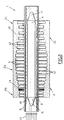
- FIG. 2 is a view in section through an axial plane of the pump shown in FIG. 1.
- Figure 3 is a schematic view of the pump in the longitudinal direction showing a method of connecting the successive windings of the inductor.
- FIG. 1 there is seen an electromagnetic linear induction pump according to the invention generally designated by the reference 1.
- the pump 1 comprises an inductor 2 which consists of a magnetic circuit 15 formed by combs 18 and coils 14 and a tubular conduit 3 in a coaxial arrangement, inside the combs 18 of the inductor 2.
- a magnetic core 4 of cylindrical shape is placed in a coaxial arrangement inside the tubular conduit 3, opposite the inductor 2.
- the laminated magnetic circuit 15 of the inductor 2 is formed by combs 18 formed by magnetic sheets juxtaposed in radial direction.
- Each of the sheets of the magnetic circuit 15 of the inductor 2 is cut to form successive notches whose section is substantially rectangular.
- the cut-outs of the juxtaposed magnetic sheets constituting the combs 18 of the magnetic circuit 15 make it possible to form, inside the combs 18 of the inductor, notches 5 of annular shape successively arranged in the longitudinal direction of the inductor parallel to the axis 7 of the pump which is the axis common to the tubular conduit 3 and to the inductor 2.
- the magnetic core 4 disposed inside the duct 3 is also produced in laminated form, by assembling, juxtaposed, radial direction plates cut from magnetic sheets.
- the tubular conduit 3 is fixed in a coaxial arrangement inside the inductor 2, with little play in the radial direction.
- An annular space 8 is formed between the interior surface of the conduit 3 and the exterior surface of the core 4 fixed in a coaxial arrangement inside the conduit 3.
- the conductive material circulated by the pump as shown diagrammatically by the arrows 10 in FIG. 2, circulates in an axial direction, inside the annular space 8, in the part of the conduit 3 located opposite. inductor screw 2.
- conduit 3 can be connected to a conduit of identical diameter ensuring the supply of the conductive liquid and to an outlet conduit ensuring the evacuation of the conductive liquid.
- the core 4 comprises a smooth tubular outer envelope inside which the magnetic sheets of the laminated structure of the core are fixed and two substantially ogival end portions 11 and 11 ′ which make it possible to limit the braking effect of the fluid through the magnetic core 4.
- the combs 18 of the magnetic circuit 15 of the inductor 2 comprise an annular part 12 projecting radially towards the inside of the inductor, that is to say in the direction of its axis 7, by relative to the bottom of the notches 5.
- the successive projecting parts 12 separating the notches 5 will be designated as inductor teeth.
- annular winding 14 comprising a plurality of turns which all have the axis 7 of the pump axis.
- Each of the windings 14 is connected to a phase of a polyphase alternating current source. In this way, currents flow in the turns of the windings 14 in a circumferential direction of the inductor, around the conduit 3.
- the successive windings 14 generate magnetic fields which are distributed in the axial direction of the pump and which are offset with respect to each other, because the windings are connected to different phases of the current source.
- the device according to the invention as will be explained with reference to Figures 1, 2 and 3 allows for an optimized distribution of the currents creating the magnetic field, in the axial direction of the inductor.
- a significant increase in pump efficiency can be obtained by the fact that the distribution of the currents is optimized, both with regard to the phase distribution and the intensity distribution.
- the successive teeth 12 of the inductor 2 separating the notches 5 in which the windings 14 are arranged are not all of the same width in the axial direction.
- the teeth separating the notches located at the central part 2a of the inductor 2 have a shorter length than the teeth located towards the ends 2b and 2c of the inductor located opposite screws of the inlet and outlet portions of the conduit 3.
- the teeth located in the end portion 2c disposed on the side of the outlet of the inductor, in the direction of circulation of the liquid given by the arrows 10, have a significant length relative to the teeth located in the central part 2a.
- the length of the teeth in the axial direction is therefore first decreasing, from the entry end from the inductor to the central part then increasing from the central part to the outlet end of the inductor.
- the distances between the middle parts of the notches 5 and the windings 14 located in these notches corresponding to the successive polar steps of the inductor are significantly smaller in the central part 2a of the inductor than in the end parts 2b and 2c.
- the different inductor supply currents which have phase shifts between them are not applied to windings regularly distributed along the axial length of the inductor.
- phase distribution along the length of the inductor is not linear but follows a law of variation which can be modulated by choosing the successive lengths of the teeth 12 of the inductor.
- the windings 14 arranged in the notches 5 can be connected to the successive phases of a polyphase supply, the phase distribution in the axial direction of the inductor is then determined by the lengths of the successive teeth of the inductor, that is to say ie by the distance between the notches or between the windings.
- the depth of the notches 5 is not constant along the length of the inductor 2.
- the notches have a greater depth in the central part 2a of the inductor than in the end parts 2b and 2c.
- the notches 5 of variable depth make it possible to receive coils 14 having different numbers of turns and therefore capable of creating a current density which is variable along the longitudinal direction of the inductor 2.
- the electromagnetic machine according to the invention therefore has characteristics making it possible to optimize both the phase distribution and the intensity distribution of the supply currents of the inductor, in the axial longitudinal direction of this inductor.
- FIG 3 there is shown schematically, the tubular conduit 16 and the windings 17 of the inductor of an electromagnetic pump supplied with hexaphase current.
- the notches receiving the successive windings 17 are not regularly spaced over the entire length of the inductor, the windings located in the outlet part of the pump generally being more spaced than the windings located in the other parts of the inductor.
- This arrangement is obtained by cutting the combs 18 of the magnetic circuit of the inductor, the teeth of which have a greater length towards the end corresponding to the outlet of the pump.
- the depth of the notches is not constant along the length of the inductor, the notches receiving the windings 17 having a depth in the radial direction more important in the central part of the inductor.
- the windings 17 of the central part of the inductor therefore have a greater number of turns and provide a greater number of amps / revolution than the windings situated towards the ends of the pump.
- the number of turns of the successive windings increases steadily up to a zone situated towards the central part of the inductor then decreases progressively to settle at a relatively low value and substantially constant in the part of the inductor corresponding to the outlet end of the pump.
- the first four series of six windings are connected to successive phases 1, 2, 3, 4, 5, 6 of the hexaphase supply, in the order of these phases.
- windings 17a, 17b and 17c Following these windings connected sequentially to the phases of the hexaphase supply, three windings 17a, 17b and 17c whose spacing is substantially greater than the spacing of the other windings 17 are connected to phase 1 of the polyphase power supply.
- the last winding of the inductor on the side of the output end of the pump is connected to phase 2 of the polyphase supply.
- phase 1 of the hexaphase current is shown by connecting lines.
- Phase 1 is first connected, starting from the inlet end of the pump, to windings located six by six and then to three successive windings.
- An electromagnetic pump according to the invention has a yield slightly greater than 48% and general performance that is entirely satisfactory, without increasing the length of the 'inductor, compared to pumps known in the prior art whose efficiency is less than 42%.
- the diameter of the pump duct through which the conductive liquid which is pumped is circulated is approximately 300 mm.
- a pump according to the invention having a very high flow rate, of the order of 11000 m 3 / h.
- Such a pump has a length of 5 m and the diameter of the central tubular conduit is approximately 1 m.
- the electromagnetic machine according to the invention therefore has the advantage of making it possible to obtain excellent efficiency while maintaining the general characteristics of the pump at a satisfactory level and without increasing the length of the inductor of the electromagnetic machine.
- this electromagnetic machine which can for example be a very high flow rate pump is produced without resorting to a complex electrical supply intended to supply the supply currents to multiple winding assemblies.
- the secondary sodium can be circulated by using pumps according to the invention.
- the total power of the six pumps is then 17 MW, compared to the power of 18 MW which would be necessary using the six pumps according to the prior art. Hence a power gain of 1 MW.
- the electromagnetic machine according to the invention can be a pump intended to ensure the circulation of any electrical conductive material such as the sodium of the secondary loops of a fast neutron reactor or any other pump intended to ensure the circulation of any conductive material and in particular of a metal such as zinc, magnesium, lead, mercury or lithium.
- any electrical conductive material such as the sodium of the secondary loops of a fast neutron reactor
- any other pump intended to ensure the circulation of any conductive material and in particular of a metal such as zinc, magnesium, lead, mercury or lithium.
- the electromagnetic machine according to the invention can also be used as a means of propulsion in a conductive liquid such as sea water; in this case the seawater is drawn in through an inlet end from the conduit of the electromagnetic machine functioning as a pump and ejected from the outlet end of the conduit.
- a conductive liquid such as sea water
- the electromagnetic machine according to the invention can also be produced in the form of a device for braking a flow of a conductive material or also in the form of a linear motor or a magneto-hydrodynamic generator.
- the invention can be applied in particular to the propulsion of land vehicles.
- the invention can also be transposed to induction pumps or other electromagnetic machines comprising a conduit of flat tubular shape comprising at least two large opposite flat faces and an inductor comprising combs made of magnetic sheets providing rectilinear and parallel notches separated by them. teeth directed towards at least one of the large flat faces of the duct; these pumps are in fact annular pumps from which the inductor has been unwound.
Landscapes
- Engineering & Computer Science (AREA)
- Power Engineering (AREA)
- Physics & Mathematics (AREA)
- Chemical & Material Sciences (AREA)
- Combustion & Propulsion (AREA)
- Electromagnetism (AREA)
- Fluid Mechanics (AREA)
- Linear Motors (AREA)
- Structures Of Non-Positive Displacement Pumps (AREA)
- Electromagnetic Pumps, Or The Like (AREA)
Claims (7)
- Linearinduktionselektromotor mit einer Rohrleitung (3, 16), die im wesentlichen geradlinig ist und dazu dient, ein leitendes Material aufzunehmen, das in dem Rohr zirkulieren kann, und einem Feldmagneten (2) mit einem Magnetkreis in Form von Kämmen (18) aus Magnetblech, so daß parallele Einkerbungen (5) zwischen diesen stehenbleiben und im wesentlichen parallel zu dem Außenumriß des Rohres auf einem Teil wenigstens der Peripherie angeordnet sind, wobei die einen von den anderen entlang der axialen Ausdehnung des Rohres durch Teile des Feldmagneten, die nach innen in Richtung des Rohres oder in radialer Richtung vorspringen, getrennt sind, die Zähne genannt werden, wobei wenigstens eine Spule in jeder der Einkerbungen (5) angeordnet ist und mit einer Phase einer Mehrphasenstromquelle verbunden ist,
dadurch gekennzeichnet, daß
die Zähne des Feldmagneten wenigstens eines der Teile des Feldmagneten am Rande gegenüber den Eingangs- und Ausgangsteilen (2b, 2c) des Rohres (3, 16) in Richtung der Zirkulation des leitenden Materials eine Ausdehnung in Axialrichtung haben, die größer als die axiale Ausdehnung der Zähne in einem zentralen Teil (2a) des Feldmagneten zwischen den Außenteilen ist und wenigstens zwei benachbarte Spulen (14) des Feldmagneten (2) mit zwei Phasen der Mehrphasenstromquelle verbunden sind, die nicht aufeinanderfolgende Phasen der Stromversorgung sind. - Elektromotor nach Anspruch 1, dadurch gekennzeichnet, daß die Einkerbungen (5) der Kämme des Feldmagneten eine größere Tiefe im zentralen Teil (2a) des Feldmagnenten als in den Teilen am Ende (2b, 2c) haben und Spulen (14) mit einer größeren Zahl an Windungen einschließen.
- Elektromotor nach einem der Ansprüche 1 und 2, dadurch gekennzeichnet, daß wenigstens zwei benachbarte Spulen (14) des Feldmagneten (2) mit einer gleichen Phase der elektrischen Stromversorgungsquelle verbunden sind.
- Elektromotor nach Anspruch 3, dadurch gekennzeichnet, daß wenigstens zwei aufeinanderfolgende Spulen (17a, 17b, 17c) an wenigstens einem Ende des Feldmagneten entsprechend dem Eingang und dem Ausgang des Rohres (3, 16) mit einer gleichen Phase der Mehrphasenstromquelle verbunden sind.
- Elektromotor nach einem der Ansprüche 1 bis 4, der ein Rohr (3, 16) in Form einer Röhre und einen ringförmigen Feldmagneten (2) koaxial um das Rohr (3, 16) mit Kämmen (18) in radialer Richtung, so daß ringförmige Einkerbungen (5) stehenbleiben, die durch ringförmige zähne (12), die nach innen gerichtet sind, getrennt werden und jeweils eine ringförmige Spule (14) koaxial um das Rohr (3, 16) und den Feldmagneten (2) einschließen, umfaßt, dadurch gekennzeichnet, daß er einen magnetischen Kern (4) von im wesentlichen zylindrischer Form koaxial im Inneren der Rohrleitung (3, 16) gegenüber dem Feldmagneten (2) umfaßt.
- Elektromotor nach einem der Ansprüche 1 bis 4, dadurch gekennzeichnet, daß er eine flache Rohrleitung (3, 16) mit wenigstens zwei großen, ebenen gegenüberliegenden Flächen und einen Feldmagneten (2) mit Kämmen (18) aus Magnetblechen umfaßt, so daß geradlinige und parallele Einkerbungen (5) stehenbleiben, die durch Zähne (12), die auf wenigstens eine der großen ebenen Flächen der Rohrleitung (3, 16) gerichtet sind, getrennt werden.
- Verwendung eines Elektromotors nach einem der Ansprüche 1 bis 6 als Umwälzpumpe eines Flüssigmetalls zum Kühlen eines Nuklearreaktors mit schnellen Neutronen, wie z.B. Natrium.
Applications Claiming Priority (2)
| Application Number | Priority Date | Filing Date | Title |
|---|---|---|---|
| FR9214405A FR2698742B1 (fr) | 1992-11-30 | 1992-11-30 | Machine électromagnétique à induction linéaire à répartition de flux magnétique optimisée et utilisations. |
| FR9214405 | 1992-11-30 |
Publications (2)
| Publication Number | Publication Date |
|---|---|
| EP0600759A1 EP0600759A1 (de) | 1994-06-08 |
| EP0600759B1 true EP0600759B1 (de) | 1997-01-22 |
Family
ID=9436058
Family Applications (1)
| Application Number | Title | Priority Date | Filing Date |
|---|---|---|---|
| EP93402736A Expired - Lifetime EP0600759B1 (de) | 1992-11-30 | 1993-11-08 | Elektromagnetische Linearinduktionmaschine mit einer optimalisierten Magnetflussverteilung und Verwendung |
Country Status (7)
| Country | Link |
|---|---|
| US (1) | US5415529A (de) |
| EP (1) | EP0600759B1 (de) |
| JP (1) | JPH06209561A (de) |
| KR (1) | KR100339118B1 (de) |
| CZ (1) | CZ253993A3 (de) |
| DE (1) | DE69307667D1 (de) |
| FR (1) | FR2698742B1 (de) |
Cited By (1)
| Publication number | Priority date | Publication date | Assignee | Title |
|---|---|---|---|---|
| CN110112888A (zh) * | 2019-04-17 | 2019-08-09 | 江苏大学 | 一种磁流体泵 |
Families Citing this family (21)
| Publication number | Priority date | Publication date | Assignee | Title |
|---|---|---|---|---|
| AU699877B2 (en) * | 1995-03-27 | 1998-12-17 | Lionel Gordon Johnston | Apparatus for the production of a GUF field and method of using same |
| KR100414081B1 (ko) * | 1997-12-10 | 2004-03-30 | 엘지전자 주식회사 | 리니어압축기의모터고정자제조방법 |
| US6084320A (en) * | 1998-04-20 | 2000-07-04 | Matsushita Refrigeration Company | Structure of linear compressor |
| US6342071B1 (en) * | 1999-07-08 | 2002-01-29 | Benjamin David Pless | Ambulatory blood pump |
| US20040228206A1 (en) * | 2003-05-13 | 2004-11-18 | Sadler Daniel J. | Phase mixing |
| DE102004013618B4 (de) * | 2004-03-19 | 2007-07-26 | Yxlon International Security Gmbh | Verfahren zum Betrieb einer magnetohydrodynamischen Pumpe, Flüssigmetallanode für eine Röntgenquelle sowie Röntgenstrahler |
| RU2289187C1 (ru) * | 2005-03-31 | 2006-12-10 | Федеральное государственное унитарное предприятие "Научно-исследовательский институт электрофизической аппаратуры им. Д.В. Ефремова" | Цилиндрический линейный индукционный насос |
| RU2289188C1 (ru) * | 2005-04-13 | 2006-12-10 | Федеральное государственное унитарное предприятие "Научно-исследовательский институт электрофизической аппаратуры им. Д.В. Ефремова" | Цилиндрический линейный индукционный насос |
| RU2324280C1 (ru) * | 2007-02-12 | 2008-05-10 | Федеральное государственное унитарное предприятие "Научно-исследовательский институт электрофизической аппаратуры им. Д.В. Ефремова" | Способ определения зон устойчивой и неустойчивой работы цилиндрических линейных индукционных электромагнитных насосов |
| RU2358374C1 (ru) * | 2007-12-14 | 2009-06-10 | Федеральное государственное унитарное предприятие "Научно-исследовательский институт электрофизической аппаратуры им. Д.В. Ефремова" | Индуктор трехфазного цилиндрического линейного индукционного насоса или магнитогидродинамической машины (варианты) |
| KR101242468B1 (ko) | 2011-10-12 | 2013-03-12 | 한국철도기술연구원 | 원통형 전자기식 모터용 코어 및 이를 이용한 원통형 전자기식 모터 |
| JP5887169B2 (ja) * | 2012-03-22 | 2016-03-16 | 助川電気工業株式会社 | 導電性液体用誘導電磁ポンプ |
| JP5851908B2 (ja) * | 2012-03-28 | 2016-02-03 | 三菱重工メカトロシステムズ株式会社 | 電磁ポンプ及びクエンチタンク並びに液体金属ループ |
| US10581355B1 (en) * | 2015-12-18 | 2020-03-03 | United States Of America As Represented By The Administrator Of National Aeronautics And Space Administration | Double-fed induction linear oscillating alternator |
| JP7166174B2 (ja) * | 2016-05-03 | 2022-11-07 | タタ、スティール、ネダーランド、テクノロジー、ベスローテン、フェンノートシャップ | 電磁ポンプの温度制御方法 |
| WO2020005657A1 (en) | 2018-06-29 | 2020-01-02 | Applied Materials, Inc. | Liquid lithium supply and regulation |
| US20230291295A1 (en) * | 2020-07-20 | 2023-09-14 | James L. Kirtley | Magnetohydrodynamic pump for molten salts and method of operating |
| US11283342B1 (en) * | 2021-01-07 | 2022-03-22 | Jiangsu University | Annular linear induction electromagnetic pump having axial guide vanes |
| WO2022261526A1 (en) * | 2021-06-11 | 2022-12-15 | Helion Energy, Inc. | Hybrid gettering diffusion pump |
| US12094617B2 (en) * | 2021-09-30 | 2024-09-17 | Ge-Hitachi Nuclear Energy Americas Llc | Multistage annular linear induction pump for nuclear reactors |
| US12577945B2 (en) * | 2023-05-23 | 2026-03-17 | Blue Origin Manufacturing, LLC | Pump for two-phase magnetic fluids |
Family Cites Families (14)
| Publication number | Priority date | Publication date | Assignee | Title |
|---|---|---|---|---|
| FR764834A (fr) * | 1933-02-23 | 1934-05-29 | Perfectionnements aux dispositifs électriques pour la création de forces | |
| US2698127A (en) * | 1949-04-06 | 1954-12-28 | Claude A Bowlus | Hydraulic transmission unit, pump, or compressor |
| GB699925A (en) * | 1951-05-23 | 1953-11-18 | Mini Of Supply | Improvements in or relating to pumps for liquid current-conducting material |
| US2920571A (en) * | 1952-05-23 | 1960-01-12 | English Electric Co Ltd | Electro-magnetic devices |
| GB802043A (en) * | 1955-10-10 | 1958-09-24 | British Thomson Houston Co Ltd | Improvements in and relating to electromagnetic pumps |
| US2985106A (en) * | 1958-05-28 | 1961-05-23 | Gen Electric | Thermal insulation system |
| US3147711A (en) * | 1960-02-17 | 1964-09-08 | Atomic Energy Authority Uk | Laminations and laminated structures suitable for use in electrical apparatus |
| FR1593007A (de) * | 1968-07-01 | 1970-05-25 | ||
| DE1908457B2 (de) * | 1969-02-20 | 1971-10-21 | Mehrphasige zweischicht stab wellenwicklung fuer einen linearen wanderfeldinduktor | |
| FR2082393A5 (de) * | 1970-03-13 | 1971-12-10 | Anvar | |
| GB2064229B (en) * | 1979-08-28 | 1984-04-04 | Nat Res Dev | Electrical machines |
| SU1144588A1 (ru) * | 1983-08-30 | 1991-08-07 | Предприятие П/Я А-7904 | Индуктор линейного индукционного насоса |
| SU1223817A1 (ru) * | 1984-03-11 | 1991-08-15 | Предприятие П/Я А-7904 | Цилиндрический линейный индукционный насос |
| DE4029443C2 (de) * | 1990-09-17 | 2001-10-11 | Eckart Berling | MHD-Schiffs-Strahltriebwerks-Aggregat |
-
1992
- 1992-11-30 FR FR9214405A patent/FR2698742B1/fr not_active Expired - Fee Related
-
1993
- 1993-11-08 DE DE69307667T patent/DE69307667D1/de not_active Expired - Lifetime
- 1993-11-08 EP EP93402736A patent/EP0600759B1/de not_active Expired - Lifetime
- 1993-11-25 CZ CZ932539A patent/CZ253993A3/cs unknown
- 1993-11-26 JP JP5296210A patent/JPH06209561A/ja active Pending
- 1993-11-29 KR KR1019930025591A patent/KR100339118B1/ko not_active Expired - Fee Related
- 1993-11-29 US US08/158,883 patent/US5415529A/en not_active Expired - Fee Related
Cited By (1)
| Publication number | Priority date | Publication date | Assignee | Title |
|---|---|---|---|---|
| CN110112888A (zh) * | 2019-04-17 | 2019-08-09 | 江苏大学 | 一种磁流体泵 |
Also Published As
| Publication number | Publication date |
|---|---|
| KR940012759A (ko) | 1994-06-24 |
| FR2698742B1 (fr) | 1995-02-17 |
| CZ253993A3 (en) | 1994-06-15 |
| KR100339118B1 (ko) | 2002-08-27 |
| FR2698742A1 (fr) | 1994-06-03 |
| DE69307667D1 (de) | 1997-03-06 |
| EP0600759A1 (de) | 1994-06-08 |
| JPH06209561A (ja) | 1994-07-26 |
| US5415529A (en) | 1995-05-16 |
Similar Documents
| Publication | Publication Date | Title |
|---|---|---|
| EP0600759B1 (de) | Elektromagnetische Linearinduktionmaschine mit einer optimalisierten Magnetflussverteilung und Verwendung | |
| EP1499001B1 (de) | Kühlvorrichtung für eine elektrische Maschine insbesondere für eine Synchronmaschine mit Dauermagneten | |
| FR2786334A1 (fr) | Stator de generateur alternatif destine a etre utilise dans un vehicule et procede de fabrication de celui-ci | |
| EP0766368A1 (de) | Scheibenförmiger asynchronous Elektromotor | |
| FR2795568A1 (fr) | Machine electrique rotative comportant un enroulement reduit et procede de fabrication de celle-ci | |
| FR2819117A1 (fr) | Alternateur a elements conducteurs en epingle pour vehicule automobile | |
| FR3000851A1 (fr) | Machine electrique a plusieurs entrefers et flux magnetique 3d | |
| FR2690289A1 (fr) | Barre de Roebel pour une configuration améliorée de demi-bobine destinée à un stator. | |
| FR2814585A1 (fr) | Enroulement pour tansformateur haute tension | |
| FR2664837A1 (fr) | Poste de soudure a moteur perfectionne. | |
| WO1998059409A1 (fr) | Procede de bobinage en deux plans d'encoche pour une machine electrique tournante | |
| FR2869472A1 (fr) | Bobine de stator a enroulement concentre pour une machine electrique tournante | |
| EP3528369A1 (de) | Stator einer elektrischen maschine mit doppeleinfügung von wicklungen in die einkerbungen | |
| EP0038879B1 (de) | Drehende elektrische Maschine | |
| CH715403B1 (fr) | Machine électrique rotative. | |
| WO1986003881A1 (fr) | Aimant solenoidal sans fer | |
| FR2536943A1 (fr) | Procede et dispositif de chauffage par induction d'une piece ferromagnetique a symetrie axiale et a contour irregulier | |
| EP1130748A1 (de) | Elektrische Transversalfluxmaschine mit sternförmigem Blechkern | |
| EP0221921B1 (de) | Eisenloser elektromagnet | |
| WO1986005625A1 (fr) | Aimant solenoidal a disques annulaires de type bitter | |
| FR2841701A1 (fr) | Alternateur pour vehicule automobile | |
| EP0289425B1 (de) | Alternator mit einer induzierten Wicklung, die Gleichrichtkomponenten aufweist | |
| EP4371214A1 (de) | Stator für eine elektrische drehmaschine und herstellungsverfahren | |
| FR3150365A1 (fr) | Système de transmission inductif pour transmettre de l’énergie électrique à un enroulement d’excitation de rotor | |
| WO2023285754A1 (fr) | Stator de machine électrique tournante et procédé de fabrication |
Legal Events
| Date | Code | Title | Description |
|---|---|---|---|
| PUAI | Public reference made under article 153(3) epc to a published international application that has entered the european phase |
Free format text: ORIGINAL CODE: 0009012 |
|
| 17P | Request for examination filed |
Effective date: 19940307 |
|
| AK | Designated contracting states |
Kind code of ref document: A1 Designated state(s): BE CH DE ES FR GB IT LI NL |
|
| 17Q | First examination report despatched |
Effective date: 19950608 |
|
| GRAG | Despatch of communication of intention to grant |
Free format text: ORIGINAL CODE: EPIDOS AGRA |
|
| GRAH | Despatch of communication of intention to grant a patent |
Free format text: ORIGINAL CODE: EPIDOS IGRA |
|
| GRAH | Despatch of communication of intention to grant a patent |
Free format text: ORIGINAL CODE: EPIDOS IGRA |
|
| GRAA | (expected) grant |
Free format text: ORIGINAL CODE: 0009210 |
|
| AK | Designated contracting states |
Kind code of ref document: B1 Designated state(s): BE CH DE ES FR GB IT LI NL |
|
| PG25 | Lapsed in a contracting state [announced via postgrant information from national office to epo] |
Ref country code: NL Free format text: LAPSE BECAUSE OF FAILURE TO SUBMIT A TRANSLATION OF THE DESCRIPTION OR TO PAY THE FEE WITHIN THE PRESCRIBED TIME-LIMIT Effective date: 19970122 Ref country code: IT Free format text: LAPSE BECAUSE OF FAILURE TO SUBMIT A TRANSLATION OF THE DESCRIPTION OR TO PAY THE FEE WITHIN THE PRE;WARNING: LAPSES OF ITALIAN PATENTS WITH EFFECTIVE DATE BEFORE 2007 MAY HAVE OCCURRED AT ANY TIME BEFORE 2007. THE CORRECT EFFECTIVE DATE MAY BE DIFFERENT FROM THE ONE RECORDED.SCRIBED TIME-LIMIT Effective date: 19970122 Ref country code: GB Effective date: 19970122 Ref country code: ES Free format text: THE PATENT HAS BEEN ANNULLED BY A DECISION OF A NATIONAL AUTHORITY Effective date: 19970122 |
|
| REG | Reference to a national code |
Ref country code: CH Ref legal event code: EP |
|
| REF | Corresponds to: |
Ref document number: 69307667 Country of ref document: DE Date of ref document: 19970306 |
|
| PG25 | Lapsed in a contracting state [announced via postgrant information from national office to epo] |
Ref country code: DE Effective date: 19970423 |
|
| NLV1 | Nl: lapsed or annulled due to failure to fulfill the requirements of art. 29p and 29m of the patents act | ||
| GBV | Gb: ep patent (uk) treated as always having been void in accordance with gb section 77(7)/1977 [no translation filed] |
Effective date: 19970122 |
|
| PLBE | No opposition filed within time limit |
Free format text: ORIGINAL CODE: 0009261 |
|
| STAA | Information on the status of an ep patent application or granted ep patent |
Free format text: STATUS: NO OPPOSITION FILED WITHIN TIME LIMIT |
|
| PG25 | Lapsed in a contracting state [announced via postgrant information from national office to epo] |
Ref country code: LI Free format text: LAPSE BECAUSE OF NON-PAYMENT OF DUE FEES Effective date: 19971130 Ref country code: CH Free format text: LAPSE BECAUSE OF NON-PAYMENT OF DUE FEES Effective date: 19971130 Ref country code: BE Free format text: LAPSE BECAUSE OF NON-PAYMENT OF DUE FEES Effective date: 19971130 |
|
| 26N | No opposition filed | ||
| BERE | Be: lapsed |
Owner name: FRAMATOME Effective date: 19971130 |
|
| REG | Reference to a national code |
Ref country code: CH Ref legal event code: PL |
|
| PGFP | Annual fee paid to national office [announced via postgrant information from national office to epo] |
Ref country code: FR Payment date: 20031119 Year of fee payment: 11 |
|
| PG25 | Lapsed in a contracting state [announced via postgrant information from national office to epo] |
Ref country code: FR Free format text: LAPSE BECAUSE OF NON-PAYMENT OF DUE FEES Effective date: 20050729 |
|
| REG | Reference to a national code |
Ref country code: FR Ref legal event code: ST |