EP0599992B1 - Entlüftbares einschraubbares proportionalventil - Google Patents
Entlüftbares einschraubbares proportionalventil Download PDFInfo
- Publication number
- EP0599992B1 EP0599992B1 EP92918551A EP92918551A EP0599992B1 EP 0599992 B1 EP0599992 B1 EP 0599992B1 EP 92918551 A EP92918551 A EP 92918551A EP 92918551 A EP92918551 A EP 92918551A EP 0599992 B1 EP0599992 B1 EP 0599992B1
- Authority
- EP
- European Patent Office
- Prior art keywords
- proportioning valve
- piston
- vented
- valve body
- accordance
- Prior art date
- Legal status (The legal status is an assumption and is not a legal conclusion. Google has not performed a legal analysis and makes no representation as to the accuracy of the status listed.)
- Expired - Lifetime
Links
Images
Classifications
-
- B—PERFORMING OPERATIONS; TRANSPORTING
- B60—VEHICLES IN GENERAL
- B60T—VEHICLE BRAKE CONTROL SYSTEMS OR PARTS THEREOF; BRAKE CONTROL SYSTEMS OR PARTS THEREOF, IN GENERAL; ARRANGEMENT OF BRAKING ELEMENTS ON VEHICLES IN GENERAL; PORTABLE DEVICES FOR PREVENTING UNWANTED MOVEMENT OF VEHICLES; VEHICLE MODIFICATIONS TO FACILITATE COOLING OF BRAKES
- B60T11/00—Transmitting braking action from initiating means to ultimate brake actuator without power assistance or drive or where such assistance or drive is irrelevant
- B60T11/10—Transmitting braking action from initiating means to ultimate brake actuator without power assistance or drive or where such assistance or drive is irrelevant transmitting by fluid means, e.g. hydraulic
- B60T11/16—Master control, e.g. master cylinders
-
- B—PERFORMING OPERATIONS; TRANSPORTING
- B60—VEHICLES IN GENERAL
- B60T—VEHICLE BRAKE CONTROL SYSTEMS OR PARTS THEREOF; BRAKE CONTROL SYSTEMS OR PARTS THEREOF, IN GENERAL; ARRANGEMENT OF BRAKING ELEMENTS ON VEHICLES IN GENERAL; PORTABLE DEVICES FOR PREVENTING UNWANTED MOVEMENT OF VEHICLES; VEHICLE MODIFICATIONS TO FACILITATE COOLING OF BRAKES
- B60T8/00—Arrangements for adjusting wheel-braking force to meet varying vehicular or ground-surface conditions, e.g. limiting or varying distribution of braking force
- B60T8/26—Arrangements for adjusting wheel-braking force to meet varying vehicular or ground-surface conditions, e.g. limiting or varying distribution of braking force characterised by producing differential braking between front and rear wheels
- B60T8/262—Arrangements for adjusting wheel-braking force to meet varying vehicular or ground-surface conditions, e.g. limiting or varying distribution of braking force characterised by producing differential braking between front and rear wheels using valves with stepped characteristics
- B60T8/265—Arrangements for adjusting wheel-braking force to meet varying vehicular or ground-surface conditions, e.g. limiting or varying distribution of braking force characterised by producing differential braking between front and rear wheels using valves with stepped characteristics for hydraulic brake systems
-
- Y—GENERAL TAGGING OF NEW TECHNOLOGICAL DEVELOPMENTS; GENERAL TAGGING OF CROSS-SECTIONAL TECHNOLOGIES SPANNING OVER SEVERAL SECTIONS OF THE IPC; TECHNICAL SUBJECTS COVERED BY FORMER USPC CROSS-REFERENCE ART COLLECTIONS [XRACs] AND DIGESTS
- Y10—TECHNICAL SUBJECTS COVERED BY FORMER USPC
- Y10T—TECHNICAL SUBJECTS COVERED BY FORMER US CLASSIFICATION
- Y10T137/00—Fluid handling
- Y10T137/7722—Line condition change responsive valves
- Y10T137/7781—With separate connected fluid reactor surface
- Y10T137/7835—Valve seating in direction of flow
Definitions
- the present invention relates generally to a proportioning valve, and in particular to a vented screw-in proportioning valve.
- a proportioning valve As a screw-in proportioning valve mounted directly to the master cylinder body at an outlet for the rear brakes.
- GB-A-2 131 107 discloses a screw-in proportioning valve that may be mounted on a master cylinder body outlet. This can contribute to eliminating the utilization of a separate body for the proportioning valve and other devices such as a fluid pressure failure warning switch mechanism which may also be incorporated into the body of the master cylinder.
- Some screw-in valves such as those illustrated in U. S. Patents Nos. 4,893,878 and 4,957,140 utilize a poppet which necessitates the use of relatively small holes for fluid flow. This can result in poor valve performance at various apply rates and temperatures. Also, because of the small piston and seat diameters used in a poppet type valve, friction variation has a greater affect on the pressure tolerance at the knee point of the desired pressure curve.
- the vented screw-in proportioning valve of the present invention provides solutions to the above by providing a vented screw-in proportioning valve, comprising a proportioning valve body having at one end an outlet and at an opposite end an inlet, threads at the opposite end for mounting said proportioning valve body, a stepped bore extending through said proportioning valve body so said inlet communicates with said outlet, a differential area piston disposed within said bore, the piston having a plurality of radially extending fluid flow apertures communicating with an interior cavity in said piston, fluid seal means located within said stepped bore and located adjacent an end of said piston, axially spaced-apart seal members located in the stepped bore and disposed about said piston to define a vented chamber, vent means extending through said proportioning valve body and communicating with said vented chamber, a retainer located within said stepped bore and positioned by abutment means located at said body, spring means engaging the retainer in order to bias said piston toward said outlet, characterized in that the piston is generally U-shaped in cross section and the spring means extends
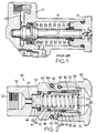
- Figure 1 illustrates a proportioning valve contained within a body 10 that is separate from the body of the associated master cylinder.
- Differential area piston 11 is biased by spring 12 seated against screw-in retainer cap or end closure 13. Fluid flow enters through inlet 14 and exits around the head of differential area piston 11 and through outlet 15 and toward the rear brakes of the vehicle.
- Valve body 10 may also include a partially shown fluid pressure failure warning switch 16 which senses fluid pressure loss in the primary or secondary fluid circuits. It is desirable to provide a proportioning valve which may be attached directly as a unit to an outlet boss of the master cylinder body, thus either eliminating or contributing to eliminating the utilization of body 10 as a separate structure.
- master cylinder body 20 includes boss 22 having internal thread 23.
- Body 20 includes outlet 24 which permits the transmission of fluid pressure toward the not shown rear brakes of the vehicle.
- the vented screw-in proportioning valve of the present invention is designated generally by reference numeral 30.
- Proportioning valve 30 includes body 32 having outlet 33 and inlet 34 communicating with master cylinder outlet 24.
- Body 32 includes exterior threads 36 which engage interior threads 23 of master cylinder body 20.
- Stepped bore 38 extends through the length of body 32 in order to communicate inlet 34 with outlet 33.
- Differential area piston 40 is located within the stepped bore and comprises a generally U-shaped piston having interior cavity 42 which communicates with fluid flow apertures 44 that permit fluid from outlet 24, inlet 34 to communicate past fluid seal 50, about piston head 46 and through transverse slot 47 to outlet 33.
- Piston 40 includes large diameter portion or outer shoulder 48 which provides a seat for seal member 52 located axially spaced apart from associated seal member 54.
- Centering ring 56 is located about piston end 47 and seats against valve body shoulder 35. Centering ring 56 provides slidable guidance for piston 40 within stepped bore 38. Seal member 54 seats against centering ring 56. Seal members 52, 54 engage the exterior surface of piston 40 and the surface of stepped bore 38 to define vented chamber 60.
- Vented chamber 60 communicates with vent 62 that is closed by vent seal 64.
- Vent seal 64 permits the transmission of air past the seal while at the same time preventing large contaminants such as water, dirt, etc. from entering stepped bore 38.
- Large diameter portion 48 not only provides the larger area of differential area piston 40, but defines, along with seal member 52, a portion of vented chamber 60.
- Stepped bore 38 includes at body end 39 a snap ring 70 which provides a seat for retainer 80.
- Cup-shaped retainer 80 includes a plurality of fluid flow passages 82, provides a seat for spring 90, and retains the seal member 54 in the illustrated axial position.
- Spring 90 seats at one end against piston head 46 and at the other end against retainer 80.
- Retainer 80 is spring-biased into position against snap ring 70.
- Static seal 92 is located about the exterior of valve body 32 and engages the interior of boss 22.
- Vented screw-in proportioning valve 30 of the present invention provides a valve that is easily mounted to an exterior boss of the master cylinder body so that the fluid pressure for the rear brakes is proportioned at the master cylinder rather than at some remote location.
Landscapes
- Engineering & Computer Science (AREA)
- Transportation (AREA)
- Mechanical Engineering (AREA)
- Details Of Valves (AREA)
- Hydraulic Control Valves For Brake Systems (AREA)
- Lift Valve (AREA)
- Extrusion Moulding Of Plastics Or The Like (AREA)
- Mechanically-Actuated Valves (AREA)
Claims (10)
- Entlüftetes, einschraubbares Zumeßventil mit einem Zumeßventilgehäuse (32), das an einem Ende einen Auslaß (33) und an einem entgegengesetzten Ende einen Einlaß (34) besitzt, einem Gewinde (36) an dem entgegengesetzten Ende zum Befestigen des Zumeßventilgehäuses (32), einer Stufenbohrung (38), die durch das Zumeßventilgehäuse (32) so verläuft, daß der Einlaß (34) mit dem Auslaß (33) in Verbindung steht, einem Stufenkolben (40), der in der Bohrung (38) angeordnet ist, wobei der Kolben (40) mehrere radial verlaufende Strömungsdurchlässe (44) aufweist, die mit einem Innenraum (42) in dem Kolben (40) in Verbindung stehen, Dichtmitteln (50), die in der Stufenbohrung (38) angrenzend an einem Ende des Kolbens (40) angeordnet sind, axial beabstandeten Dichtkörpern (52,54), die in der Stufenbohrung (38) angeordnet sind und den Kolben (40) umgeben, um eine Entlüftungskammer (60) zu bilden, Entlüftungsmitteln (62), die durch das Zumeßventilgehäuse (32) verlaufen und mit der Entlüftungskammer (60) in Verbindung stehen, einem Halter (80), der in der Stufenbohrung (38) angeordnet ist und durch an dem Gehäuse (32) angeordnete Anschlagmittel (70) positioniert wird, Federmitteln (90), die an dem Halter (80) angreifen, um den Kolben (40) in Richtung auf den Auslaß (33) vorzuspannen, dadurch gekennzeichnet, daß der Kolben (40) einen allgemein U-förmigen Querschnitt hat und die Federmittel (90) in dem Innenraum (42) des Kolbens (40) verlaufen, und daß ein Zentrierring (56) und einer (54) der Dichtkörper (52,54) um den Kolben (40) herum angeordnet sind und eine Gleitführung für den Kolben (40) innerhalb der Bohrung (38) bilden, wobei der Zentrierring (56) und ein Dichtkörper (54) von dem Halter (80) axial festgelegt werden.
- Entlüftetes, einschraubbares Zumeßventil nach Anspruch 1, dadurch gekennzeichnet, daß der Halter (80) durch die Federmittel (90) in Anlage mit den Anschlagmitteln (70) vorgespannt wird.
- Entlüftetes, einschraubbares Zumeßventil nach Anspruch 2, dadurch gekennzeichnet, daß die Anschlagmittel (70) einen Schnappring (70) aufweisen.
- Entlüftetes, einschraubbares Zumeßventil nach Anspruch 3, dadurch gekennzeichnet, daß der Halter (80) mehrere Durchgangskanäle (82) für die Strömung aufweist.
- Entlüftetes, einschraubbares Zumeßventil nach Anspruch 1, dadurch gekennzeichnet, daß das Zumeßventil ferner eine statische Dichtung (92) aufweist, die um das Zumeßventilgehäuse (32) herum angrenzend an dem Gewinde (36) angeordnet ist.
- Entlüftetes, einschraubbares Zumeßventil nach Anspruch 1, dadurch gekennzeichnet, daß das Zumeßventil ferner eine Entlüftungsdichtung (64) aufweist, die um das Zumeßventilgehäuse (32) herum angeordnet ist, um Schmutz am Eindringen in die Entlüftungsmittel (62) zu hindern.
- Entlüftetes, einschraubbares Zumeßventil nach Anspruch 1 in Verbindung mit einem Hauptzylinder, dadurch gekennzeichnet, daß das Gewinde (36) um das Äußere des Zumeßventilgehäuses (32) herum angeordnet ist und mit einem Innengewinde (23) eines Ansatzes (22) des Hauptzylinders in Eingriff steht.
- Entlüftetes, einschraubbares Zumeßventil nach Anspruch 1, dadurch gekennzeichnet, daß der Kolben (40) einen Abschnitt (48) großen Durchmessers aufweist, der zusammen mit dem anderen (52) der beabstandeten Dichtkörper (52,54) einen Abschnitt der Entlüftungskammer (60) bildet.
- Entlüftetes, einschraubbares Zumeßventil nach Anspruch 1, dadurch gekennzeichnet, daß der Kolben (40) einen Kopf (46) aufweist, der mindestens einen querverlaufenden Schlitz (47) besitzt, um für eine Strömung mit dem Auslaß (33) zu sorgen.
- Entlüftetes, einschraubbares Zumeßventil nach Anspruch 1, dadurch gekennzeichnet, daß die Dichtmittel (50) um das Ende des Kolbens (40) herum angeordnet sind, um benachbart hierzu zu sein, derart, daß das Strömungsmittel durch den Innenraum (42) und die Durchlässe (44) vorbei an den Dichtmitteln (50) und einem Ende des Kolbens (40) strömt, so daß der Auslaß (33) zu dem Einlaß (34) linear ausgerichtet ist.
Applications Claiming Priority (3)
| Application Number | Priority Date | Filing Date | Title |
|---|---|---|---|
| US751428 | 1991-08-28 | ||
| US07/751,428 US5144976A (en) | 1991-08-28 | 1991-08-28 | Vented screw-in proportioning valve |
| PCT/US1992/006795 WO1993004901A1 (en) | 1991-08-28 | 1992-08-13 | Vented screw-in proportioning valve |
Publications (2)
| Publication Number | Publication Date |
|---|---|
| EP0599992A1 EP0599992A1 (de) | 1994-06-08 |
| EP0599992B1 true EP0599992B1 (de) | 1995-10-18 |
Family
ID=25021932
Family Applications (1)
| Application Number | Title | Priority Date | Filing Date |
|---|---|---|---|
| EP92918551A Expired - Lifetime EP0599992B1 (de) | 1991-08-28 | 1992-08-13 | Entlüftbares einschraubbares proportionalventil |
Country Status (7)
| Country | Link |
|---|---|
| US (1) | US5144976A (de) |
| EP (1) | EP0599992B1 (de) |
| JP (1) | JP2729194B2 (de) |
| KR (1) | KR100230073B1 (de) |
| AU (1) | AU657244B2 (de) |
| DE (1) | DE69205580T2 (de) |
| WO (1) | WO1993004901A1 (de) |
Families Citing this family (5)
| Publication number | Priority date | Publication date | Assignee | Title |
|---|---|---|---|---|
| EP0523033A1 (de) * | 1991-07-10 | 1993-01-13 | IMS Ionen Mikrofabrikations Systeme Gesellschaft m.b.H. | Ionenoptisches Abbildungssystem |
| SE504346C2 (sv) * | 1995-05-15 | 1997-01-20 | Haldex Ab | Inloppsventil för en lufttorkare |
| GB2524975A (en) * | 2014-04-07 | 2015-10-14 | Weatherford Uk Ltd | Vent valve and method of use |
| DE202014003386U1 (de) * | 2014-04-22 | 2015-07-27 | Neoperl Gmbh | Druckreduzierventil |
| CN113090786A (zh) * | 2021-03-08 | 2021-07-09 | 海南立昇净水科技实业有限公司 | 单向逆止排气阀 |
Family Cites Families (6)
| Publication number | Priority date | Publication date | Assignee | Title |
|---|---|---|---|---|
| DE1076996B (de) * | 1957-09-26 | 1960-03-03 | Bosch Gmbh Robert | Fluessigkeitsgesteuertes Kraftstoff-einspritzventil |
| JPS5174174A (en) * | 1974-12-25 | 1976-06-26 | Nissan Motor | Bureekyuatsuseigyoben |
| US4000684A (en) * | 1975-03-27 | 1977-01-04 | Numatics, Incorporated | Safety lock-out valve |
| FR2536147A1 (fr) * | 1982-11-15 | 1984-05-18 | Kelsey Hayes Co | Soupape de dosage |
| US4893878A (en) * | 1988-09-27 | 1990-01-16 | Hilite Industries, Inc. | Inline proportioning valve for brake systems |
| US4957140A (en) * | 1989-04-21 | 1990-09-18 | Nippon Air Brake Co., Ltd. | Hydraulic pressure control valve for use with brake master cylinder |
-
1991
- 1991-08-28 US US07/751,428 patent/US5144976A/en not_active Expired - Fee Related
-
1992
- 1992-08-13 WO PCT/US1992/006795 patent/WO1993004901A1/en not_active Ceased
- 1992-08-13 EP EP92918551A patent/EP0599992B1/de not_active Expired - Lifetime
- 1992-08-13 DE DE69205580T patent/DE69205580T2/de not_active Expired - Fee Related
- 1992-08-13 AU AU24865/92A patent/AU657244B2/en not_active Ceased
- 1992-08-13 JP JP5505210A patent/JP2729194B2/ja not_active Expired - Fee Related
- 1992-08-13 KR KR1019940700668A patent/KR100230073B1/ko not_active Expired - Fee Related
Also Published As
| Publication number | Publication date |
|---|---|
| WO1993004901A1 (en) | 1993-03-18 |
| US5144976A (en) | 1992-09-08 |
| JP2729194B2 (ja) | 1998-03-18 |
| AU2486592A (en) | 1993-04-05 |
| EP0599992A1 (de) | 1994-06-08 |
| JPH06506169A (ja) | 1994-07-14 |
| DE69205580D1 (de) | 1995-11-23 |
| AU657244B2 (en) | 1995-03-02 |
| DE69205580T2 (de) | 1996-04-04 |
| KR100230073B1 (ko) | 1999-11-15 |
Similar Documents
| Publication | Publication Date | Title |
|---|---|---|
| JP4570368B2 (ja) | ガス制御組立体 | |
| EP0352261B1 (de) | Ventilbaueinheit für proportionierungsventil | |
| US3945686A (en) | Blend back proportioning valve | |
| US4080004A (en) | Service and emergency trailer valve | |
| US3993361A (en) | Pressure protection valve and system | |
| US4616677A (en) | Manifold fitting for a compressed air tank | |
| US5144976A (en) | Vented screw-in proportioning valve | |
| US6846408B2 (en) | Filter assembly for a control valve in a vehicular brake system | |
| CA1153405A (en) | Back-to-back proportioning valve | |
| US4042281A (en) | Service and emergency trailer valve | |
| US4163585A (en) | Service and emergency trailer valve | |
| US4738109A (en) | Two stage brake control valve | |
| CA1116209A (en) | Hydraulic anti-skid device | |
| EP0494161B1 (de) | Differenzdruckpendelventil | |
| US4076328A (en) | Tractor-trailer parking dash control valve with two-way check valve | |
| EP0777074B1 (de) | Verbesserungen an Druckentlastungsventilen | |
| US6213566B1 (en) | Brake proportioning in-line ball valve | |
| GB2131107A (en) | Proportioning valve | |
| US4711092A (en) | Light switch and brake line connector assembly | |
| GB1530753A (en) | Fluid pressure control valve for vehicle braking systems | |
| US3988041A (en) | Apparatus for preventing release of an emergency brake application prior to a complete stop of the train | |
| CA1120975A (en) | Fluid pressure generator and valve member therefor | |
| KR100210474B1 (ko) | 유압라인 차단용 컨넥터 | |
| JPS6211727Y2 (de) | ||
| US3903920A (en) | Hydraulic flow control assemblies |
Legal Events
| Date | Code | Title | Description |
|---|---|---|---|
| PUAI | Public reference made under article 153(3) epc to a published international application that has entered the european phase |
Free format text: ORIGINAL CODE: 0009012 |
|
| 17P | Request for examination filed |
Effective date: 19940223 |
|
| AK | Designated contracting states |
Kind code of ref document: A1 Designated state(s): DE FR GB IT |
|
| RAP1 | Party data changed (applicant data changed or rights of an application transferred) |
Owner name: ALLIEDSIGNAL INC. |
|
| 17Q | First examination report despatched |
Effective date: 19950131 |
|
| GRAA | (expected) grant |
Free format text: ORIGINAL CODE: 0009210 |
|
| AK | Designated contracting states |
Kind code of ref document: B1 Designated state(s): DE FR GB IT |
|
| ET | Fr: translation filed | ||
| REF | Corresponds to: |
Ref document number: 69205580 Country of ref document: DE Date of ref document: 19951123 |
|
| ITF | It: translation for a ep patent filed | ||
| PLBE | No opposition filed within time limit |
Free format text: ORIGINAL CODE: 0009261 |
|
| 26N | No opposition filed | ||
| REG | Reference to a national code |
Ref country code: FR Ref legal event code: TP |
|
| REG | Reference to a national code |
Ref country code: GB Ref legal event code: 732E |
|
| REG | Reference to a national code |
Ref country code: GB Ref legal event code: IF02 |
|
| PGFP | Annual fee paid to national office [announced via postgrant information from national office to epo] |
Ref country code: FR Payment date: 20020823 Year of fee payment: 11 |
|
| PGFP | Annual fee paid to national office [announced via postgrant information from national office to epo] |
Ref country code: DE Payment date: 20020925 Year of fee payment: 11 |
|
| PGFP | Annual fee paid to national office [announced via postgrant information from national office to epo] |
Ref country code: GB Payment date: 20030729 Year of fee payment: 12 |
|
| PG25 | Lapsed in a contracting state [announced via postgrant information from national office to epo] |
Ref country code: DE Free format text: LAPSE BECAUSE OF NON-PAYMENT OF DUE FEES Effective date: 20040302 |
|
| PG25 | Lapsed in a contracting state [announced via postgrant information from national office to epo] |
Ref country code: FR Free format text: LAPSE BECAUSE OF NON-PAYMENT OF DUE FEES Effective date: 20040430 |
|
| REG | Reference to a national code |
Ref country code: FR Ref legal event code: ST |
|
| PG25 | Lapsed in a contracting state [announced via postgrant information from national office to epo] |
Ref country code: GB Free format text: LAPSE BECAUSE OF NON-PAYMENT OF DUE FEES Effective date: 20040813 |
|
| GBPC | Gb: european patent ceased through non-payment of renewal fee |
Effective date: 20040813 |
|
| PG25 | Lapsed in a contracting state [announced via postgrant information from national office to epo] |
Ref country code: IT Free format text: LAPSE BECAUSE OF NON-PAYMENT OF DUE FEES Effective date: 20050813 |