EP0599320B1 - Einspritzdruckregeleinrichtung eines Kraftstoffeinspritzventils für Dieselmotoren - Google Patents
Einspritzdruckregeleinrichtung eines Kraftstoffeinspritzventils für Dieselmotoren Download PDFInfo
- Publication number
- EP0599320B1 EP0599320B1 EP93119031A EP93119031A EP0599320B1 EP 0599320 B1 EP0599320 B1 EP 0599320B1 EP 93119031 A EP93119031 A EP 93119031A EP 93119031 A EP93119031 A EP 93119031A EP 0599320 B1 EP0599320 B1 EP 0599320B1
- Authority
- EP
- European Patent Office
- Prior art keywords
- piston
- injection
- speed
- stroke
- rotation
- Prior art date
- Legal status (The legal status is an assumption and is not a legal conclusion. Google has not performed a legal analysis and makes no representation as to the accuracy of the status listed.)
- Expired - Lifetime
Links
- 238000002347 injection Methods 0.000 title claims description 75
- 239000007924 injection Substances 0.000 title claims description 75
- 239000000446 fuel Substances 0.000 title claims description 32
- 230000007423 decrease Effects 0.000 claims description 6
- 238000011161 development Methods 0.000 description 14
- 230000018109 developmental process Effects 0.000 description 14
- 238000010586 diagram Methods 0.000 description 6
- 238000002485 combustion reaction Methods 0.000 description 4
- 230000000694 effects Effects 0.000 description 2
- 238000011017 operating method Methods 0.000 description 2
- 230000002411 adverse Effects 0.000 description 1
- 230000005540 biological transmission Effects 0.000 description 1
- 230000005284 excitation Effects 0.000 description 1
- 239000000463 material Substances 0.000 description 1
- 238000012986 modification Methods 0.000 description 1
- 230000004048 modification Effects 0.000 description 1
- 230000000630 rising effect Effects 0.000 description 1
Images

Classifications
-
- F—MECHANICAL ENGINEERING; LIGHTING; HEATING; WEAPONS; BLASTING
- F02—COMBUSTION ENGINES; HOT-GAS OR COMBUSTION-PRODUCT ENGINE PLANTS
- F02M—SUPPLYING COMBUSTION ENGINES IN GENERAL WITH COMBUSTIBLE MIXTURES OR CONSTITUENTS THEREOF
- F02M57/00—Fuel-injectors combined or associated with other devices
- F02M57/02—Injectors structurally combined with fuel-injection pumps
-
- F—MECHANICAL ENGINEERING; LIGHTING; HEATING; WEAPONS; BLASTING
- F02—COMBUSTION ENGINES; HOT-GAS OR COMBUSTION-PRODUCT ENGINE PLANTS
- F02M—SUPPLYING COMBUSTION ENGINES IN GENERAL WITH COMBUSTIBLE MIXTURES OR CONSTITUENTS THEREOF
- F02M59/00—Pumps specially adapted for fuel-injection and not provided for in groups F02M39/00 -F02M57/00, e.g. rotary cylinder-block type of pumps
- F02M59/02—Pumps specially adapted for fuel-injection and not provided for in groups F02M39/00 -F02M57/00, e.g. rotary cylinder-block type of pumps of reciprocating-piston or reciprocating-cylinder type
- F02M59/10—Pumps specially adapted for fuel-injection and not provided for in groups F02M39/00 -F02M57/00, e.g. rotary cylinder-block type of pumps of reciprocating-piston or reciprocating-cylinder type characterised by the piston-drive
- F02M59/102—Mechanical drive, e.g. tappets or cams
-
- F—MECHANICAL ENGINEERING; LIGHTING; HEATING; WEAPONS; BLASTING
- F02—COMBUSTION ENGINES; HOT-GAS OR COMBUSTION-PRODUCT ENGINE PLANTS
- F02B—INTERNAL-COMBUSTION PISTON ENGINES; COMBUSTION ENGINES IN GENERAL
- F02B3/00—Engines characterised by air compression and subsequent fuel addition
- F02B3/06—Engines characterised by air compression and subsequent fuel addition with compression ignition
Definitions
- the present invention relates to a control system for the injection pressure of an electromagnetically actuated fuel injector for a diesel cycle engine, by means of which it is possible to obtain relatively high maximum injection pressures even at low speeds of rotation of the engine and fuel flow rates which increase gradually during each injection cycle.
- injectors each of which comprises an injection piston, moving at a speed which normally increases proportionally to the speed of rotation of the engine and which is adapted to inject the fuel via an injection hole controlled by an electromagnetically actuated shutter member; this shutter member is adapted to open this injection hole when the piston has performed a predetermined stroke.
- the injection piston of each injector is normally controlled by a cam carried by a camshaft actuated by the engine.
- the profile of this cam is normally selected in order to control the piston so that it moves, during its entire forward stroke, at a speed which increases proportionally to the angle of rotation of this cam and in order to control the piston so that it moves, during its return stroke, at a speed which decreases proportionally to the angle of rotation of the cam.
- the diagram representing the development of the speed of the injection piston as a function of the angle of rotation of the cam, in each injection cycle is formed by a continuous curve with two rectilinear sides, one of whose values increase and the other of whose values decrease in a linear manner as the angle of rotation of the cam increases.
- the fuel pressure within the injector increases, during the forward stroke of the injection piston, until it reaches the maximum value; thereafter, the pressure decreases, during the return stroke of the piston, until it is cancelled out.
- the value of this maximum pressure is more or less directly proportional to the value of the maximum speed of the piston and inversely proportional to the cross-section of the injection hole.
- the ratio between the maximum fuel pressures obtained during injection cycles corresponding to two different speeds of rotation of the engine is rather high; when these two speeds are, for instance, equivalent to 2000 and 1000 revolutions per minute respectively, this ratio is approximately 2.
- the fuel is injected in a rather abrupt manner, since the rates of flow of the fuel injected by unit of angular rotation are rather high, with the result that there is unsatisfactory mixing and combustion of the fuel, and likely to cause very high pressures in the combustion chamber and to form non-combusted material.
- EP-A-0 413 454 discloses a control system for the injection pressure of a fuel injector, the features of which form the basis of the preamble of claim 1. However, such a control system does not solve the aforesaid problems completely.
- the object of the present invention is to provide a control system for the injection pressure of a fuel injector for a diesel cycle engine which remedies the drawbacks described above.
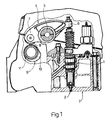
- the injection pressure control system of the invention may be embodied in a diesel cycle engine of the type shown in Fig. 1, which substantially comprises an injector, shown overall by 1, of a conventional electromagnetically actuated type, in whose housing an injection piston (not shown) moves; this injector is adapted to inject fuel via an injection hole 2 provided on the head 3 of the engine; the injection hole 2 is controlled by a moving shutter member (not shown) which opens the injection hole when the shutter member is displaced by the action of an electromagnet under the effect of an excitation command.
- the injector 1 is actuated by a rocker arm 4 oscillating about a shaft 5 and is provided with a pair of arms 6 and 7, the first of which is able to exert, via appropriate transmission members, predetermined forces on the piston of the injector 1 in order to pressurize the fuel contained therein; the other arm 7 of the rocker arm 4 is provided with a roller 8 adapted to bear on the profile 9 of a cam 10 borne by a camshaft 11 actuated by the engine.
- the injector 1 is secured to the head 3 by appropriate connection members, some of which are shown in Fig. 1.
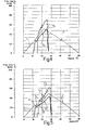
- Fig. 2 shows the development of the speed of the injection piston during its forward stroke (shown by the line t) and during its return stroke (shown by the line t') as a function of the angle of rotation of the cam 10). It will be appreciated from this Figure that the development of the speed, as a function of the angle of rotation of the cam, may be approximately shown by a triangular diagram having predetermined sides t and t'.
- the injection piston is caused to advance over a first portion of its forward stroke at a speed which increases proportionally to this stroke, over a second portion of its stroke at a speed which is constant and over a third portion of this stroke at a speed which again increases proportionally to the stroke.
- the profile 9 of the cam 10 is selected to control the injection piston so that it moves, during each injection cycle, over a first portion of its forward stroke at a speed which increases proportionally to the angle of rotation of the cam, over a second portion of its stroke at a speed which is constant as this angle increases and over a third portion of its stroke at a speed which again increases proportionally to the angle of rotation of the cam.
- the lines t 1 , t 2 and t 3 represent the development of the speed of the injection piston as a function of the angle of rotation of the cam in the three forward stroke portions as defined above: it can be seen that while the initial and final portions (lines t 1 and t 3 ) of the piston stroke are travelled at speeds which increase in a linear manner, the intermediate stroke portion (line t 2 ) is travelled at a constant speed.
- the system of the invention further comprises appropriate actuation means able to control the movement of the shutter member of the injector in order to open the injection hole 2 at any point during the forward stroke of the injector piston and, therefore, after this piston has performed a predetermined stroke.
- the predetermined stroke of the piston at which the opening of the shutter member of the injector is controlled and fuel injection consequently begins is selected along the first portion of the forward stroke of the piston and therefore at a point of the peak t 1 shown by A in Fig. 3; moreover, during each injection cycle and for a predetermined second speed of rotation of the engine n 2 lower than the first speed n 1 , the above-mentioned predetermined stroke of the piston, at which opening of the shutter member of the injector is controlled and fuel injection consequently commences, is selected along the second portion of the forward stroke of the piston and therefore at a point of the line t 2 shown by B in Fig. 3.
- the second predetermined speed n 2 is advantageously between 30 and 70% of the first predetermined speed n 1 ; these speeds may, for instance, be equal to 2000 and 1000 revolutions per minute respectively.
- the angle of rotation of the cam 9 during the second portion of the forward stroke of the injection piston is between 15% and 25% of the angle of rotation of the cam which is needed to perform the entire forward stroke of the piston (represented by the sum of the lines t 1 , t 2 and t 3 ).
- the diagram of the speed of advance of the piston as a function of the angle of rotation of the cam 10 includes sections t 1 and t 3 (Fig. 3) having the same gradient as the line t of Fig. 2, that the lines t' of Figs. 1 and 3 have the same gradient and lastly that the active angle of rotation of the cam 10 is the same in both cases (60°).
- V max the maximum speed of the piston
- the fuel injection pressure increases with the development shown by the curves p 1 and p 2 ; if it is supposed that injection commences in each of the two cycles when the pressure p o is reached, in the case of the first cycle the point A corresponds to this pressure on the curve t 1 and in the case of the second cycle the point B corresponds to the same pressure on the curve t 2 .
- the development of the injection pressure p 1 in the first cycle is therefore particularly influenced by the presence of the portion of the stroke with a constant speed shown by the section t 2 of the curve, while the development of the injection pressure p 2 in the second cycle is only partially influenced by this section, starting injection at the point B located at the end of the section t 2 .
- the system of the invention makes it possible to achieve this pressure with a cross-section of the injection hole of the injector which is smaller than that needed with the conventional system.
- This result can be seen from a ccmparison of the curves of Figs. 2 and 3 in which the maximum value of the pressures p 1 is the same (and may correspond to that compatible with the mechanical strength of some components of the systems): in order to achieve this result, the system of the invention uses an injector whose injection hole has smaller dimensions that those of the injector used in the conventional system.
- FIGs. 4 and 5 show the developments of the rates of flow per unit of angular rotation of the cam 10 as a function of the angle of rotation of this cam, respectively in the case of the conventional pressure control system and that of the invention (Fig. 5).
- the curves shown by q 1 and q 2 in these Figures show the rates of flow of fuel injected obtained respectively at the two above-mentioned reference speeds n 1 and n 2 .
- a comparison of the diagrams of these Figures shows that with the control system of the invention the rate of introduction of the fuel into the cylinders is much more gradual with the advantage that more regular and more complete combustion of the fuel is obtained.
- the movement of the injection cylinder of the injector 1 may be obtained using a kinematic mechanism differing from that shown, comprising the rocker arm 4 and the cam 10, provided that a rate of variation of the speed of the piston as a function of its stroke of the type described and illustrated is provided.
Landscapes
- Engineering & Computer Science (AREA)
- Chemical & Material Sciences (AREA)
- Combustion & Propulsion (AREA)
- Mechanical Engineering (AREA)
- General Engineering & Computer Science (AREA)
- Fuel-Injection Apparatus (AREA)
Claims (5)
- Steuerungssystem für den Einspritzdruck eines elektromagnetisch betätigten Kraftstoffeinspritzventils (1) für einen Dieselmotor, wobei dieses Einspritzventil einen Einspritzkolben aufweist, der sich bei einer Geschwindigkeit bewegt, die sich proportional zu der Drehgeschwindigkeit des Motors vergrößert und mit einem sich bewegenden Verschlußelement versehen ist, das derart gestaltet ist, daß eine Einspritzöffnung (2) geöffnet wird, um den Kraftstoff einzuspritzen, wenn der Kolben einen vorbestimmten Hub durchgeführt hat; wobei der Einspritzkolben während eines jeden Einspritzzyklus veranlaßt wird, sich über einen ersten Abschnitt seines Vorwärtshubes bei einer Geschwindigkeit voranzubewegen, die sich proportional zu diesem Hub vergrößert, sich über einen zweiten Abschnitt seines Hubes bei einer konstanten Geschwindigkeit voranzubewegen, und sich über einen dritten Abschnitt seines Hubes bei einer Geschwindigkeit voranzubewegen, die sich wiederum proportional zu dem Hub vergrößert,
dadurch gekennzeichnet , daß
während eines jeden Einspritzzyklus und für eine erste vorbestimmte Drehgeschwindigkeit des Motors (n1) der vorbestimmte Hub des Kolbens, bei dem die Kraftstoffeinspritzung beginnt, entlang des ersten Abschnitts des Vorwärtshubes des Kolbens gewählt wird, und daß für eine zweite Drehgeschwindigkeit des Motors (n2), die geringer ist als die erste vorbestimmte Geschwindigkeit, der vorbestimmte Hub des Kolbens, bei dem die Kraftstoffeinspritzung beginnt, entlang des zweiten Abschnitts des Vorwärtshubes des Kolbens gewählt wird. - System nach Anspruch 1,
dadurch gekennzeichnet, daß
die zweite vorbestimmte Geschwindigkeit (n2) zwischen 30% und 70% der ersten vorbestimmten Geschwindigkeit (n1) liegt. - System nach Anspruch 1 oder 2,
wobei der sich bewegende Kolben durch einen Nocken (10) gesteuert wird, der durch eine Nockenwelle (11) getragen wird, die durch den Motor betätigt wird. - System nach Anspruch 3,
dadurch gekennzeichnet, daß
das Profil (9) des Nockens (10) so gewählt wird, daß der Kolben derart gesteuert wird, daß er sich während seines Rückhubes bei einer Geschwindigkeit bewegt, die sich proportional zu dem Drehwinkel des Nockens verringert. - System nach einem der Ansprüche 3 oder 4,
dadurch gekennzeichnet, daß
der Drehwinkel des Nockens (10) während des zweiten Abschnitts des Vorwärtshubes des Kolbens zwischen 15% und 25% des Drehwinkels des Nockens liegt, der für die Durchführung des gesamten Vorwärtshubes des Kolbens erforderlich ist.
Applications Claiming Priority (2)
| Application Number | Priority Date | Filing Date | Title |
|---|---|---|---|
| ITTO920962A IT1257558B (it) | 1992-11-27 | 1992-11-27 | Sistema per il controllo della pressione di iniezione di un iniettore di carburante per un motore a ciclo diesel. |
| ITTO920962 | 1992-11-27 |
Publications (2)
| Publication Number | Publication Date |
|---|---|
| EP0599320A1 EP0599320A1 (de) | 1994-06-01 |
| EP0599320B1 true EP0599320B1 (de) | 1997-07-16 |
Family
ID=11410886
Family Applications (1)
| Application Number | Title | Priority Date | Filing Date |
|---|---|---|---|
| EP93119031A Expired - Lifetime EP0599320B1 (de) | 1992-11-27 | 1993-11-25 | Einspritzdruckregeleinrichtung eines Kraftstoffeinspritzventils für Dieselmotoren |
Country Status (4)
| Country | Link |
|---|---|
| EP (1) | EP0599320B1 (de) |
| DE (1) | DE69312227T2 (de) |
| ES (1) | ES2106256T3 (de) |
| IT (1) | IT1257558B (de) |
Family Cites Families (2)
| Publication number | Priority date | Publication date | Assignee | Title |
|---|---|---|---|---|
| JPH0652069B2 (ja) * | 1985-05-14 | 1994-07-06 | 株式会社ゼクセル | 燃料噴射ポンプ |
| GB8918600D0 (en) * | 1989-08-15 | 1989-09-27 | Lucas Ind Plc | Unit injector |
-
1992
- 1992-11-27 IT ITTO920962A patent/IT1257558B/it active IP Right Grant
-
1993
- 1993-11-25 DE DE69312227T patent/DE69312227T2/de not_active Expired - Lifetime
- 1993-11-25 EP EP93119031A patent/EP0599320B1/de not_active Expired - Lifetime
- 1993-11-25 ES ES93119031T patent/ES2106256T3/es not_active Expired - Lifetime
Also Published As
| Publication number | Publication date |
|---|---|
| DE69312227D1 (de) | 1997-08-21 |
| IT1257558B (it) | 1996-01-30 |
| ITTO920962A1 (it) | 1994-05-27 |
| EP0599320A1 (de) | 1994-06-01 |
| ITTO920962A0 (it) | 1992-11-27 |
| DE69312227T2 (de) | 1998-01-08 |
| ES2106256T3 (es) | 1997-11-01 |
Similar Documents
| Publication | Publication Date | Title |
|---|---|---|
| US4633837A (en) | Method for controlling fuel injection in internal combustion engines and fuel injection system for performing the method | |
| US4249497A (en) | Fuel injection apparatus having at least one fuel injection valve for high-powered engines | |
| US5056488A (en) | Fuel injection system in particular unit fuel injector, for internal combustion engines | |
| EP0619423B1 (de) | Krafstoffeinspritzvorrichtung | |
| JPH02157470A (ja) | 空気圧縮内燃機関の電磁弁制御燃料噴射装置 | |
| US5533481A (en) | Fuel Injection system | |
| US6988680B1 (en) | Injector of compact design for a common rail injection system for internal combustion engines | |
| EP0987430B1 (de) | Brennstoffeinspritzventil | |
| US4881504A (en) | Fuel injection pump | |
| US6016786A (en) | Fuel injection system | |
| EP0599320B1 (de) | Einspritzdruckregeleinrichtung eines Kraftstoffeinspritzventils für Dieselmotoren | |
| US4763631A (en) | Fuel injection pump for internal combustion engines | |
| WO2006101424A1 (en) | Method for controlling a fuel injector | |
| EP0844384B1 (de) | Einspritzventil | |
| US4391257A (en) | Fuel injection pump for internal combustion engines | |
| GB2304817A (en) | Electronic fuel injector with metering chamber and timing chamber | |
| JPH031508B2 (de) | ||
| US5647325A (en) | Fuel injection device for internal combustion engines | |
| US5144925A (en) | Fuel injection device for fuel-injected internal combustion engines | |
| KR100206235B1 (ko) | 디젤 엔진용 연료 제어 기구 | |
| JP3014908B2 (ja) | インジェクタの燃料噴射圧力制御装置 | |
| JPH04209962A (ja) | 燃料噴射装置 | |
| EP0884467B1 (de) | Kraftstoffeinspritzanlage eines Dieselmotors | |
| JPH08529Y2 (ja) | 燃料噴射装置 | |
| US20030164404A1 (en) | Fuel-injection valve for internal combustion engines |
Legal Events
| Date | Code | Title | Description |
|---|---|---|---|
| PUAI | Public reference made under article 153(3) epc to a published international application that has entered the european phase |
Free format text: ORIGINAL CODE: 0009012 |
|
| AK | Designated contracting states |
Kind code of ref document: A1 Designated state(s): CH DE ES FR GB IT LI SE |
|
| 17P | Request for examination filed |
Effective date: 19941018 |
|
| 17Q | First examination report despatched |
Effective date: 19950922 |
|
| GRAG | Despatch of communication of intention to grant |
Free format text: ORIGINAL CODE: EPIDOS AGRA |
|
| GRAH | Despatch of communication of intention to grant a patent |
Free format text: ORIGINAL CODE: EPIDOS IGRA |
|
| GRAH | Despatch of communication of intention to grant a patent |
Free format text: ORIGINAL CODE: EPIDOS IGRA |
|
| GRAA | (expected) grant |
Free format text: ORIGINAL CODE: 0009210 |
|
| AK | Designated contracting states |
Kind code of ref document: B1 Designated state(s): CH DE ES FR GB IT LI SE |
|
| REG | Reference to a national code |
Ref country code: CH Ref legal event code: EP |
|
| REF | Corresponds to: |
Ref document number: 69312227 Country of ref document: DE Date of ref document: 19970821 |
|
| REG | Reference to a national code |
Ref country code: CH Ref legal event code: NV Representative=s name: ISLER & PEDRAZZINI AG |
|
| ITF | It: translation for a ep patent filed | ||
| ET | Fr: translation filed | ||
| REG | Reference to a national code |
Ref country code: ES Ref legal event code: FG2A Ref document number: 2106256 Country of ref document: ES Kind code of ref document: T3 |
|
| PLBE | No opposition filed within time limit |
Free format text: ORIGINAL CODE: 0009261 |
|
| STAA | Information on the status of an ep patent application or granted ep patent |
Free format text: STATUS: NO OPPOSITION FILED WITHIN TIME LIMIT |
|
| 26N | No opposition filed | ||
| REG | Reference to a national code |
Ref country code: GB Ref legal event code: IF02 |
|
| REG | Reference to a national code |
Ref country code: CH Ref legal event code: PFA Owner name: NISSAN DIESEL MOTOR CO., LTD. Free format text: NISSAN DIESEL MOTOR CO., LTD.#1-1, AGEO#SAITAMA 362 (JP) $ IVECO FIAT S.P.A.#VIA PUGLIA 35#10156 TORINO (IT) -TRANSFER TO- NISSAN DIESEL MOTOR CO., LTD.#1-1, AGEO#SAITAMA 362 (JP) $ IVECO S.P.A.#VIA PUGLIA 35#10156 TORINO (IT) |
|
| REG | Reference to a national code |
Ref country code: FR Ref legal event code: CD |
|
| PG25 | Lapsed in a contracting state [announced via postgrant information from national office to epo] |
Ref country code: IT Free format text: LAPSE BECAUSE OF NON-PAYMENT OF DUE FEES;WARNING: LAPSES OF ITALIAN PATENTS WITH EFFECTIVE DATE BEFORE 2007 MAY HAVE OCCURRED AT ANY TIME BEFORE 2007. THE CORRECT EFFECTIVE DATE MAY BE DIFFERENT FROM THE ONE RECORDED. Effective date: 20051125 |
|
| REG | Reference to a national code |
Ref country code: ES Ref legal event code: PC2A |
|
| REG | Reference to a national code |
Ref country code: CH Ref legal event code: PCAR Free format text: ISLER & PEDRAZZINI AG;POSTFACH 1772;8027 ZUERICH (CH) |
|
| PGRI | Patent reinstated in contracting state [announced from national office to epo] |
Ref country code: IT Effective date: 20110616 |
|
| REG | Reference to a national code |
Ref country code: FR Ref legal event code: TQ Owner name: FPT INDUSTRIAL S.P.A. (FIAT POWERTRAIN TECHNOL, IT Effective date: 20111212 Ref country code: FR Ref legal event code: TQ Owner name: NISSAN DIESEL MOTOR CO., LTD., JP Effective date: 20111212 Ref country code: FR Ref legal event code: CD Owner name: FPT INDUSTRIAL S.P.A. (FIAT POWERTRAIN TECHNOL, IT Effective date: 20111212 Ref country code: FR Ref legal event code: CD Owner name: NISSAN DIESEL MOTOR CO., LTD., JP Effective date: 20111212 |
|
| REG | Reference to a national code |
Ref country code: ES Ref legal event code: PC2A Owner name: FPT INDUSTRIAL S.P.A. Effective date: 20120222 |
|
| REG | Reference to a national code |
Ref country code: DE Ref legal event code: R082 Ref document number: 69312227 Country of ref document: DE Representative=s name: HOFFMANN - EITLE, DE |
|
| REG | Reference to a national code |
Ref country code: DE Ref legal event code: R082 Ref document number: 69312227 Country of ref document: DE Representative=s name: HOFFMANN - EITLE PATENT- UND RECHTSANWAELTE PA, DE Effective date: 20120402 Ref country code: DE Ref legal event code: R082 Ref document number: 69312227 Country of ref document: DE Representative=s name: HOFFMANN - EITLE, DE Effective date: 20120402 Ref country code: DE Ref legal event code: R081 Ref document number: 69312227 Country of ref document: DE Owner name: FPT INDUSTRIAL S.P.A., IT Free format text: FORMER OWNERS: IVECO S.P.A., TURIN, IT; NISSAN DIESEL MOTOR CO., LTD., AGEO, SAITAMA, JP Effective date: 20120402 Ref country code: DE Ref legal event code: R081 Ref document number: 69312227 Country of ref document: DE Owner name: FPT INDUSTRIAL S.P.A., IT Free format text: FORMER OWNER: IVECO S.P.A., NISSAN DIESEL MOTOR CO., LTD., , JP Effective date: 20120402 |
|
| PGFP | Annual fee paid to national office [announced via postgrant information from national office to epo] |
Ref country code: CH Payment date: 20121018 Year of fee payment: 20 Ref country code: FR Payment date: 20121114 Year of fee payment: 20 Ref country code: DE Payment date: 20121018 Year of fee payment: 20 |
|
| PGFP | Annual fee paid to national office [announced via postgrant information from national office to epo] |
Ref country code: GB Payment date: 20121004 Year of fee payment: 20 Ref country code: SE Payment date: 20121018 Year of fee payment: 20 Ref country code: ES Payment date: 20121020 Year of fee payment: 20 Ref country code: IT Payment date: 20121107 Year of fee payment: 20 |
|
| REG | Reference to a national code |
Ref country code: DE Ref legal event code: R071 Ref document number: 69312227 Country of ref document: DE |
|
| REG | Reference to a national code |
Ref country code: DE Ref legal event code: R071 Ref document number: 69312227 Country of ref document: DE |
|
| REG | Reference to a national code |
Ref country code: CH Ref legal event code: PL |
|
| REG | Reference to a national code |
Ref country code: GB Ref legal event code: PE20 Expiry date: 20131124 |
|
| REG | Reference to a national code |
Ref country code: SE Ref legal event code: EUG |
|
| PG25 | Lapsed in a contracting state [announced via postgrant information from national office to epo] |
Ref country code: DE Free format text: LAPSE BECAUSE OF EXPIRATION OF PROTECTION Effective date: 20131126 Ref country code: GB Free format text: LAPSE BECAUSE OF EXPIRATION OF PROTECTION Effective date: 20131124 |
|
| REG | Reference to a national code |
Ref country code: ES Ref legal event code: FD2A Effective date: 20140925 |
|
| PG25 | Lapsed in a contracting state [announced via postgrant information from national office to epo] |
Ref country code: ES Free format text: LAPSE BECAUSE OF EXPIRATION OF PROTECTION Effective date: 20131126 |