EP0599204B1 - Submersible pump assembly - Google Patents
Submersible pump assembly Download PDFInfo
- Publication number
- EP0599204B1 EP0599204B1 EP93118605A EP93118605A EP0599204B1 EP 0599204 B1 EP0599204 B1 EP 0599204B1 EP 93118605 A EP93118605 A EP 93118605A EP 93118605 A EP93118605 A EP 93118605A EP 0599204 B1 EP0599204 B1 EP 0599204B1
- Authority
- EP
- European Patent Office
- Prior art keywords
- housing
- submersible pump
- pump unit
- unit according
- flow
- Prior art date
- Legal status (The legal status is an assumption and is not a legal conclusion. Google has not performed a legal analysis and makes no representation as to the accuracy of the status listed.)
- Expired - Lifetime
Links
Images

Classifications
-
- F—MECHANICAL ENGINEERING; LIGHTING; HEATING; WEAPONS; BLASTING
- F04—POSITIVE - DISPLACEMENT MACHINES FOR LIQUIDS; PUMPS FOR LIQUIDS OR ELASTIC FLUIDS
- F04D—NON-POSITIVE-DISPLACEMENT PUMPS
- F04D7/00—Pumps adapted for handling specific fluids, e.g. by selection of specific materials for pumps or pump parts
- F04D7/02—Pumps adapted for handling specific fluids, e.g. by selection of specific materials for pumps or pump parts of centrifugal type
- F04D7/04—Pumps adapted for handling specific fluids, e.g. by selection of specific materials for pumps or pump parts of centrifugal type the fluids being viscous or non-homogenous
-
- F—MECHANICAL ENGINEERING; LIGHTING; HEATING; WEAPONS; BLASTING
- F04—POSITIVE - DISPLACEMENT MACHINES FOR LIQUIDS; PUMPS FOR LIQUIDS OR ELASTIC FLUIDS
- F04D—NON-POSITIVE-DISPLACEMENT PUMPS
- F04D13/00—Pumping installations or systems
- F04D13/02—Units comprising pumps and their driving means
- F04D13/06—Units comprising pumps and their driving means the pump being electrically driven
- F04D13/08—Units comprising pumps and their driving means the pump being electrically driven for submerged use
- F04D13/086—Units comprising pumps and their driving means the pump being electrically driven for submerged use the pump and drive motor are both submerged
-
- F—MECHANICAL ENGINEERING; LIGHTING; HEATING; WEAPONS; BLASTING
- F04—POSITIVE - DISPLACEMENT MACHINES FOR LIQUIDS; PUMPS FOR LIQUIDS OR ELASTIC FLUIDS
- F04D—NON-POSITIVE-DISPLACEMENT PUMPS
- F04D29/00—Details, component parts, or accessories
- F04D29/40—Casings; Connections of working fluid
- F04D29/42—Casings; Connections of working fluid for radial or helico-centrifugal pumps
- F04D29/44—Fluid-guiding means, e.g. diffusers
- F04D29/445—Fluid-guiding means, e.g. diffusers especially adapted for liquid pumps
-
- F—MECHANICAL ENGINEERING; LIGHTING; HEATING; WEAPONS; BLASTING
- F05—INDEXING SCHEMES RELATING TO ENGINES OR PUMPS IN VARIOUS SUBCLASSES OF CLASSES F01-F04
- F05D—INDEXING SCHEME FOR ASPECTS RELATING TO NON-POSITIVE-DISPLACEMENT MACHINES OR ENGINES, GAS-TURBINES OR JET-PROPULSION PLANTS
- F05D2260/00—Function
- F05D2260/60—Fluid transfer
- F05D2260/604—Vortex non-clogging type pumps
Definitions
- the invention relates to a submersible pump unit with the features specified in the preamble of claim 1.
- Such a submersible pump unit is described, for example, in EP-A-0 420 218.
- Such aggregates are e.g. used in the field of wastewater technology. They are used not only to convey pure or contaminated liquids, but also to transport solids carried in the liquid. Such units are therefore designed so that solid parts can be conveyed up to the size of a ball that fits through the inlet opening. They are therefore often e.g. used in the construction or food industry.
- the impeller In order to allow the passage of large solid parts, it is known to design the impeller as a single-bladed, ducted or free-flow impeller.
- the inlet opening is usually located on the underside of the pump directly below the impeller.
- the outlet opening in the form of the pressure port is usually arranged radially to the impeller.
- Such a pump is known for example from US Pat. No. 4,454,993 or US Pat. No. 4,697,746.
- these pumps are chipped in the direction of conveyance assigned in front of the impeller, which is to shred the solid particles before entering the area of the pump impeller.
- Submersible pump units with a concentric housing are also known, from which the fluid is radially discharged and then directed in a bend in the direction parallel to the axis.
- the submersible pump unit known from EP-A-0 420 218 is more favorable, the pump housing of which is designed as a molded part and has an inlet opening at the bottom and an outlet opening designed as a pressure port at the top.
- the housing wall In order to divert the essentially radial flow coming from the impeller into an essentially axially parallel one leading to the pressure port, the housing wall has a bulge. This bulge forms a kind of stowage zone.
- the efficiency is also comparatively poor there, because the flow between the deflection point in the region of the bulge and the pressure port is only due to the between the Outside of the engine and the inner wall of the unit housing is formed channel where turbulence occurs due to construction.
- the invention has for its object to provide a generic submersible pump unit with better efficiency, while keeping the slimest possible design.
- This object is achieved according to the invention in that the pressure-side flow between the bulge and the pressure port is guided through a pipe arranged within the unit housing.
- a pipe which can be integrated into the housing with little effort in terms of production technology, leads the flow on all sides and in the shortest possible way to the pressure port. It has been shown that the pressure losses which otherwise occur in this area can be reduced considerably by such a tube. In addition, a comparatively slim-line unit with a large free delivery cross section is created.
- this peripheral component on the housing wall is in the range of two to five times the nozzle speed of the respective unit.
- the transition from the storage zone to the concentric housing should be rounded, with a transition radius r ü .
- the unit can be built in a slimmer form, which increases the area of application and reduces the cost of materials.
- a simple solution consists in providing openings at the beginning and end of the pipe that lies within the unit housing and runs between the storage zone and the pressure connection. Through the openings at different pressure levels, a partial flow for motor cooling is passed through the annular space between the unit housing and the encapsulated stator.
- the unit is advantageously equipped with a single-bladed, ducted or free-flow impeller, the wall surrounding the impeller then expediently being part of a shell-shaped housing part which belongs to the unit housing and for example forms the lower part of the housing.
- a shell-shaped housing part can be formed inexpensively from cold-formed steel sheet, which also has the advantage that the roughness of the surface is very low, which in turn benefits the improvement in efficiency.
- the bulge forming the storage zone in the housing wall is advantageously designed such that the cross section of this bulge follows an arc in the storage area, the diameter this circle corresponds to that of the inlet opening and that of the pipe and the pressure nozzle. This largely ensures that everything that can enter the unit through the inlet opening is also conveyed out again, in particular does not become lodged within the unit.
- the bulge which forms the storage zone is advantageously arranged in the housing wall in such a way that, viewed in the direction of flow, it connects approximately tangentially to the concentric part of the housing wall.
- the transition radius from the storage zone to the concentric part of the housing has also proven to be influential. This transition radius r ü should be between the limits d / 8 ⁇ r ü ⁇ d / 4 move.
- FIG. 1 shows a submersible pump unit which has an encapsulated motor 1 which is seated within the essentially cylindrical unit housing 2.
- the electrical supply line 3 of the motor 1 is led out of the motor housing 4 and the unit housing 2 upwards.
- the motor housing 4 sits slightly eccentrically within the unit housing 2, an annular space 5 being formed in this area between the outer circumference of the motor housing 4 and the inside of the unit housing 2. This annular space is closed at the top by the end wall 6 of the unit housing and at the bottom by an annular end wall 7, which forms part of the actual pump housing.
- the shaft 8 of the motor 1 is led out of the motor housing 4 downwards and sealed against it in this area.
- the lower free shaft end protrudes into the pump chamber 9 and carries there an impeller 10 in the form of a free-flow impeller.
- the impeller is closed at the top by a disk-shaped impeller part 11, which is arranged perpendicular to the shaft 8 and carries impeller blades 12.
- the pump chamber 9 is delimited at the top by the lower end of the motor housing 4 and the end wall 7.
- the lateral and lower boundary is formed by a molded part 13, which is approximately bowl-shaped, consists of cold-formed sheet metal and is firmly connected to the other unit housing 2, in particular the foot 14.
- the foot 14 is flush with the cylindrical outer contour of the other unit housing 2 and (not shown) has sufficiently large recesses for the free passage of the medium.
- the molded part 13 has a circular recess 15 in the area under the impeller 10, that is, in the extension of the shaft 8, which forms the inlet opening of the pump.
- the outlet opening of the unit is formed by a pressure nozzle 16 arranged on the upper end face, which is connected to the pump chamber 9 via a pipe 17 arranged in the annular space 5 of the unit housing 2, approximately parallel to the longitudinal axis of the unit and the shaft 8.
- the tube 17 opens into the end wall 7, in the region above a bulge 18 forming a storage zone in the molded part 13.
- the tube 17 connects to the pump chamber 9 approximately at the level of the disk-shaped impeller part 11.
- the tube 17 Shortly above its connection to the pump chamber 9, but above the end wall 7, that is to say already in the region of the annular chamber 5, the tube 17 has recesses 19 in the form of circular openings. Corresponding recesses 20 are close the upper end, that is, close to the pressure connection 16 in the pipe 17. These recesses 19 and 20 are at different pressure levels during operation of the pump, so that in addition to the main flow flowing through the pipe 17, a secondary flow flowing out of the pipe 17 via the recesses 19 and re-entering via the recesses 20 adjusts the annular space 5 flows through and thus cools the engine 1. This cooling flow can be adjusted by appropriate dimensioning of the recesses 19 and 20 and other suitable fluidic measures within the annular space 5 according to the cooling requirements.
- the molded part 13 is shown in detail with reference to FIGS. 2 to 4.
- the area of the actual pump chamber it has an approximately concentric housing wall 21, which merges tangentially into the corresponding wall part of the bulge 18 in the area 22.
- the area 22 is in plan view (FIG. 2) both tangential to the concentric housing wall part 21 and to that of the bulge 18 which is eccentrically aligned with the pipe 17.
- the housing wall 21 merges upwards with a small radius into a horizontal part 23 with which it is connected to the rest of the unit housing 2. This horizontal part 23 is followed, as can be seen in FIG. 3 and FIG. 4, by a collar-shaped part 24.
- the housing wall 21 merges with a large radius into a likewise horizontal, but inwardly running wall part 25, which limits the pump chamber 9 in this area at the bottom.
- the horizontal wall part 25 runs downward like a shell toward the recess 15, this shell-shaped part is designated by 26.
- the radius r with which the housing wall 21 merges into the wall part 25 corresponds to the radius r of the bulge 18, which in this area has a spherical surface follows.
- the radius r is half the diameter d of the inlet opening 15, the pipe 17.
- This diameter d also corresponds approximately to the distance between the impeller and the underlying housing parts of the molded part 13. In this way, a free passage of the order of one Ball with the aforementioned diameter d guaranteed by the entire pump unit.
- a projection 28 is formed in the opposite direction, where the tangents of the housing wall parts 21 of the concentric part and the bulge 18 intersect.
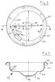
- the geometric relationships of the molded part 13 have already been explained in the introduction, they are shown in detail in FIG. 2.
- the ball diameter of the largest ball is indicated with d, which can be conveyed through the unit with the flow.
- D denotes the diameter of the concentric part of the pump housing, that is to say in the concentric region of the housing wall 21.
- the bulge 18, which follows a spherical surface with the radius r, is arranged such that the center M of this sphere lies on an arc of a diameter B arranged concentrically with the pump impeller 10.
- transition radius r ü already mentioned at the beginning is one sixth of the ball diameter in the embodiment shown, but it can be between an eighth and a quarter of the ball diameter d d / 4 ⁇ r ü ⁇ d / 8.
- the ball diameter d not only determines the design of the molded part 13, but in the same way the diameter of the recess 15, that of the tube 17 and that of the adjoining pressure connector 16.
- the unit When the pump is operating, the unit is partially or completely immersed in the liquid to be pumped.
- the pumped medium enters the pump chamber 9 through the inlet opening 15 and is set in motion by the impeller 10, namely in the radial and tangential directions. It is then guided through the housing wall 21 and directed over the area 22 to the bulge 18.
- a storage zone now forms here, the conveying liquid is deflected upwards, where it enters the pipe 17 and finally exits at the pressure connection 16.
- the partial flow for cooling that is formed has already been described above.
Description
Die Erfindung betrifft ein Tauchpumpenaggregat mit denen im Oberbegriff des Anspruchs 1 angegebenen Merkmalen.The invention relates to a submersible pump unit with the features specified in the preamble of
Ein solches Tauchpumpenaggregat ist beispielsweise in EP-A-0 420 218 beschrieben. Derartige Aggregate werden z.B. im Bereich der Abwassertechnik eingesetzt. Sie dienen dabei nicht nur zur Förderung reiner oder verschmutzter Flüssigkeiten, sondern auch zum Transport von in der Flüssigkeit mitgeführten Feststoffen. Solche Aggregate sind daher konstruktiv so ausgelegt, daß Feststoffteile bis zur Größe einer durch die Einlaßöffnung passenden Kugel gefördert werden können. Sie werden daher auch häufig z.B. in der Bau- oder Nahrungsmittelindustrie verwendet.Such a submersible pump unit is described, for example, in EP-A-0 420 218. Such aggregates are e.g. used in the field of wastewater technology. They are used not only to convey pure or contaminated liquids, but also to transport solids carried in the liquid. Such units are therefore designed so that solid parts can be conveyed up to the size of a ball that fits through the inlet opening. They are therefore often e.g. used in the construction or food industry.
Um den Durchgang von großen Feststoffteilen zu ermöglichen, ist es bekannt, das Laufrad als Einschaufel-, Kanal- oder Freistromlaufrad auszubilden. Die Einlaßöffnung befindet sich in der Regel an der Unterseite der Pumpe direkt unter dem Laufrad. Die Auslaßöffnung in Form des Druckstutzens ist in der Regel radial zum Laufrad angeordnet. Eine solche Pumpe ist beispielsweise aus US-PS 4,454,993 oder US-PS 4,697,746 bekannt. Diesen Pumpen ist allerdings ein Schnitzelwerk in Förderrichtung vor dem Laufrad zugeordnet, das die Feststoffteile vor Eintritt in den Bereich des Pumpenlaufrades zerkleinern soll.In order to allow the passage of large solid parts, it is known to design the impeller as a single-bladed, ducted or free-flow impeller. The inlet opening is usually located on the underside of the pump directly below the impeller. The outlet opening in the form of the pressure port is usually arranged radially to the impeller. Such a pump is known for example from US Pat. No. 4,454,993 or US Pat. No. 4,697,746. However, these pumps are chipped in the direction of conveyance assigned in front of the impeller, which is to shred the solid particles before entering the area of the pump impeller.
Weiter sind Tauchpumpenaggregate mit konzentrischem Gehäuse bekannt, aus dem das Fluid radial abgeführt und danach in einem Krümmer in die achsparallele Richtung gelenkt wird.Submersible pump units with a concentric housing are also known, from which the fluid is radially discharged and then directed in a bend in the direction parallel to the axis.
All diesen bekannten Tauchpumpenaggregaten gemeinsam ist ein vergleichsweise schlechter Wirkungsgrad, da innerhalb des Pumpengehäuses bei der Umwandlung kinetischer in potentielle Energie große Verluste auftreten. Ein weiterer Nachteil dieser Bauart besteht darin, daß aufgrund des radial herausgeführten Druckstutzens das Pumpenaggregat vergleichsweise ausladend baut, was insbesondere dann von Nachteil ist, wenn es um den Einsatz in engen Schächten, Rohren oder dergleichen geht.All these known submersible pump units have in common a comparatively poor efficiency, since large losses occur within the pump housing during the conversion of kinetic to potential energy. Another disadvantage of this type of construction is that due to the radially led out pressure connection, the pump assembly is relatively bulky, which is particularly disadvantageous when it is used in narrow shafts, pipes or the like.
Hinsichtlich der radialen Baugröße günstiger ist insoweit das aus EP-A-0 420 218 bekannte Tauchpumpenaggregat, dessen Pumpengehäuse als Formteil ausgebildet ist und unten eine Einlaßöffnung und oben eine als Druckstutzen ausgebildete Auslaßöffnung aufweist. Um die vom Laufrad kommende, im wesentlichen radiale Strömung in eine im wesentlichen achsparallele, zum Druckstutzen führende umzulenken, weist die Gehäusewand eine Ausbuchtung auf. Diese Ausbuchtung bildet eine Art Stauzone. Zwar ist das dort beschriebene Pumpenaggregat hinsichtlich der radialen Baugröße deutlich schlanker als die anhand der vorerwähnten US-Patente beschriebenen, doch ist der Wirkungsgrad auch dort vergleichsweise schlecht, da nämlich die Strömung zwischen der Umlenkstelle im Bereich der Ausbuchtung und dem Druckstutzen lediglich durch den zwischen der Außenseite des Motors und der Innenwand des Aggregatgehäuses gebildeten Kanal geführt wird, wo konstruktionsbedingt Verwirbelungen auftreten.With regard to the radial size, the submersible pump unit known from EP-A-0 420 218 is more favorable, the pump housing of which is designed as a molded part and has an inlet opening at the bottom and an outlet opening designed as a pressure port at the top. In order to divert the essentially radial flow coming from the impeller into an essentially axially parallel one leading to the pressure port, the housing wall has a bulge. This bulge forms a kind of stowage zone. Although the pump assembly described there is significantly slimmer in terms of radial size than that described with the aid of the aforementioned U.S. patents, the efficiency is also comparatively poor there, because the flow between the deflection point in the region of the bulge and the pressure port is only due to the between the Outside of the engine and the inner wall of the unit housing is formed channel where turbulence occurs due to construction.
Ausgehend von diesem Stand der Technik liegt der Erfindung die Aufgabe zugrunde, ein gattungsgemäßes Tauchpumpenaggregat mit besserem Wirkungsgrad zu schaffen, wobei eine möglichst schlanke Bauform erhalten bleiben soll.Based on this prior art, the invention has for its object to provide a generic submersible pump unit with better efficiency, while keeping the slimest possible design.
Diese Aufgabe wird gemäß der Erfindung dadurch gelöst, daß die druckseitige Strömung zwischen der Ausbuchtung und dem Druckstutzen durch ein innerhalb des Aggregatgehäuses angeordnetes Rohr geführt wird. Ein solches Rohr, das herstellungstechnisch mit geringem Aufwand innerhalb des Gehäuses integrierbar ist, führt die Strömung allseitig und auf kürzestem Weg gezielt zum Druckstutzen. Es hat sich gezeigt, daß die sonst in diesem Bereich auftretenden Drucksverluste durch ein solches Rohr ganz erheblich verringert werden können. Darüberhinaus wird ein vergleichsweise schlank bauendes Aggregat mit großem freien Förderquerschnitt geschaffen.This object is achieved according to the invention in that the pressure-side flow between the bulge and the pressure port is guided through a pipe arranged within the unit housing. Such a pipe, which can be integrated into the housing with little effort in terms of production technology, leads the flow on all sides and in the shortest possible way to the pressure port. It has been shown that the pressure losses which otherwise occur in this area can be reduced considerably by such a tube. In addition, a comparatively slim-line unit with a large free delivery cross section is created.
Bei der vorliegenden Erfindung wird im Vergleich zu bekannten Konstruktionen ein deutlich besserer Wirkungsgrad erreicht, da die Umwandlung von kinetischer in potentielle Energie verlustärmer erfolgt. Die im Bereich der Stauzone vorgenommene Umlenkung der Strömung in die achsparallele Richtung unter gleichzeitiger Reduzierung der Geschwindigkeit auf das Druckstutzenniveau gewährleistet eine verlustarme Energieumwandlung im Druckbereich des Aggregats.In the present invention, a significantly better efficiency is achieved compared to known designs, since the conversion from kinetic to potential energy takes place with less loss. The deflection of the flow in the area of the stowage zone in the direction parallel to the axis while simultaneously reducing the speed to the pressure port level ensures low-loss energy conversion in the pressure area of the unit.
Die Umfangskomponente der das Laufrad verlassenden Strömung cu baut sich nach dem Flächensatz![]()
![]()
Versuche haben gezeigt, daß der zusätzliche Druckhöhenaufbau durch die erfindungsgemäße Lösung - bei der der Mittelpunkt M der Ausbuchtung auf dem Durchmesser D des konzentrischen Gehäuses liegt und der Radius dieser Ausbuchtung dem halben Kugeldurchmesser entspricht, wobei der Grund der Ausbuchtung Teil einer Kugelfläche ist - verglichen mit einem Tauchpumpenaggregat gleicher Förderleistung und gleichem freien Förderdurchgang nach dem Stand der Technik in der Größenordnung von 6 bis 10 % der von der Pumpe geleisteten Förderhöhe liegt. Dieser Prozentsatz ist etwa der Verbesserung des Pumpenwirkungsgrades gleichzusetzen.Experiments have shown that the additional pressure head build-up by the solution according to the invention - in which the center M of the bulge lies on the diameter D of the concentric housing and the radius of this bulge corresponds to half the ball diameter, the base of the bulge being part of a spherical surface - compared with a submersible pump unit with the same delivery rate and the same free delivery passage according to the state of the art in the order of 6 to 10% of the delivery rate achieved by the pump. This percentage is roughly equivalent to improving pump efficiency.
Neben der Wirkungsgraderhöhung durch die verbesserte Fluidstromführung innerhalb des Aggregates ergibt sich der Vorteil, daß das Aggregat in schlankerer Form gebaut werden kann, wodurch der Einsatzbereich vergrößert und der Materialaufwand verringert wird.In addition to the increase in efficiency due to the improved fluid flow inside the unit, there is the advantage that the unit can be built in a slimmer form, which increases the area of application and reduces the cost of materials.
Die Baugröße des Aggregats, insbesondere des Motors, kann verringert werden, wenn stets eine ausreichende Kühlung gewährleistet werden kann. Diese erfolgt besonders effektiv, wenn man die Förderflüssigkeit als Kühlflüssigkeit einsetzt. Eine einfache Lösung besteht darin, das innerhalb des Aggregatgehäuses liegende und zwischen Stauzone und Druckstutzen verlaufende Rohr am Anfang und Ende mit Durchbrechungen zu versehen. Durch die auf verschiedenem Druckniveau liegenden Öffnungen wird ein Teilförderstrom zur Motorkühlung durch den Ringraum zwischen Aggregatgehäuse und gekapseltem Stator geleitet.The size of the unit, especially the motor, can be reduced if adequate cooling can always be guaranteed. This is particularly effective when the liquid is used as a cooling liquid. A simple solution consists in providing openings at the beginning and end of the pipe that lies within the unit housing and runs between the storage zone and the pressure connection. Through the openings at different pressure levels, a partial flow for motor cooling is passed through the annular space between the unit housing and the encapsulated stator.
Um bei einem möglichst großen freien Förderdurchgang einen vergleichsweise guten Wirkungsgrad zu erreichen, wird das Aggregat vorteilhaft mit einem Einschaufel-, Kanal- oder einem Freistromlaufrad ausgerüstet, wobei die das Kreiselrad umgebende Wand dann zweckmäßigerweise Teil eines schalenförmigen Gehäuseteils ist, das zum Aggregatgehäuse gehört und beispielsweise den unteren Gehäuseteil bildet. Ein solches schalenförmiges Gehäuseteil kann kostengünstig aus kaltverformtem Stahlblech gebildet sein, was zudem noch den Vorteil hat, daß die Rauhigkeit der Oberfläche sehr gering ist, was wiederum der Verbesserung des Wirkungsgrades zugutekommt.In order to achieve a comparatively good efficiency with the largest possible free passage, the unit is advantageously equipped with a single-bladed, ducted or free-flow impeller, the wall surrounding the impeller then expediently being part of a shell-shaped housing part which belongs to the unit housing and for example forms the lower part of the housing. Such a shell-shaped housing part can be formed inexpensively from cold-formed steel sheet, which also has the advantage that the roughness of the surface is very low, which in turn benefits the improvement in efficiency.
Die die Stauzone bildende Ausbuchtung in der Gehäusewand wird vorteilhaft so ausgebildet, daß der Querschnitt dieser Ausbuchtung im Staubereich einem Kreisbogen folgt, wobei der Durchmesser dieses Kreises dem der Einlaßöffnung und dem des Rohrs und des Druckstutzens entspricht. Hierdurch ist weitgehend sichergestellt, daß all das, was durch die Einlaßöffnung in das Aggregat eintreten kann auch wieder herausgefördert wird, insbesondere sich nicht innerhalb des Aggregates festsetzt.The bulge forming the storage zone in the housing wall is advantageously designed such that the cross section of this bulge follows an arc in the storage area, the diameter this circle corresponds to that of the inlet opening and that of the pipe and the pressure nozzle. This largely ensures that everything that can enter the unit through the inlet opening is also conveyed out again, in particular does not become lodged within the unit.
Um eine möglichst gute Umsetzung von kinetischer in potentielle Energie zu erreichen, wird die Ausbuchtung, welche die Stauzone bildet, vorteilhaft so in der Gehäusewand angeordnet, daß sie in Strömungsrichtung gesehen etwa tangential an den konzentrischen Teil der Gehäusewand anschließt. Als einflußreich hat sich auch der Übergangsradius von der Stauzone auf den konzentrischen Teil des Gehäuses erwiesen. Dieser Übergangsradius rü sollte sich zwischen den Grenzen![]()
![]()
Insbesondere dann, wenn die Förderflüssigkeit Feststoffpartikel mitführt, wird im Bereich der Stauzone eine erhöhte abrasive Beanspruchung festzustellen sein. Es ist daher zweckmäßig, diesen Teil der Wandung entweder aus entsprechend verschleißfestem Material zu bilden oder aber mit verschleißfestem Material zu belegen.In particular, if the conveying liquid carries solid particles, an increased abrasive load will be found in the area of the storage zone. It is therefore expedient either to form this part of the wall from correspondingly wear-resistant material or to cover it with wear-resistant material.
Hieran schließt sich die ursprüngliche Beschreibung Seite 6 ff an (Die Erfindung ist nachfolgend anhand ....)This is followed by the original description on
Die Erfindung ist nachfolgend anhand eines in der Zeichnung dargestellten Ausführungsbeispieles näher erläutert. Es zeigen:
Figur 1- in stark vereinfachter Darstellung ein Tauchpumpenaggregat im Längsschnitt,
Figur 2- eine Draufsicht auf das untere Gehäuseteil des Aggregates,
- Figur 3
- einen Schnitt längs der Schnittlinie III-III in
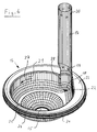
Figur 2 und Figur 4- eine perspektivische Darstellung der Pumpengehäusewand im Bereich des Laufrades und der Stauzone sowie die Anordnung des die Stauzone mit dem Druckstutzen verbindenden Rohres innerhalb des Gehäuses.
- Figure 1
- in a greatly simplified representation, a submersible pump unit in longitudinal section,
- Figure 2
- a plan view of the lower housing part of the unit,
- Figure 3
- a section along the section line III-III in Figure 2 and
- Figure 4
- a perspective view of the pump housing wall in the area of the impeller and the accumulation zone and the arrangement of the tube connecting the accumulation zone with the pressure port within the housing.
In Figur 1 ist ein Tauchpumpenaggregat dargestellt, das einen gekapselten Motor 1 aufweist, der innerhalb des im wesentlichen zylindrischen Aggregatgehäuses 2 sitzt. Die elektrische Versorgungsleitung 3 des Motors 1 ist aus dem Motorgehäuse 4 und dem Aggregatgehäuse 2 nach oben herausgeführt. Das Motorgehäuse 4 sitzt leicht außermittig innerhalb des Aggregatgehäuses 2, wobei zwischen dem Außenumfang des Motorgehäuses 4 und der Innenseite des Aggregatgehäuses 2 in diesem Bereich ein Ringraum 5 gebildet ist. Dieser Ringraum wird nach oben durch die Stirnwand 6 des Aggregatgehäuses und nach unten durch eine ringförmige Stirnwand 7 abgeschlossen, die Teil des eigentlichen Pumpengehäuses bildet.FIG. 1 shows a submersible pump unit which has an encapsulated
Die Welle 8 des Motors 1 ist aus dem Motorgehäuse 4 nach unten herausgeführt und in diesem Bereich demgegenüber abgedichtet. Das untere freie Wellenende ragt in den Pumpenraum 9 hinein und trägt dort ein Laufrad 10 in Form eines Freistromlaufrades. Das Laufrad ist nach oben hin durch ein scheibenförmiges Laufradteil 11 abgeschlossen, das senkrecht zur Welle 8 angeordnet ist und Laufradschaufeln 12 trägt.The
Der Pumpenraum 9 wird durch das untere Ende des Motorgehäuses 4 sowie die Stirnwand 7 nach oben hin begrenzt. Die seitliche und untere Begrenzung wird durch ein Formteil 13 gebildet, das etwa schüsselförmig ausgeformt ist, aus kaltverformten Blech besteht und mit dem übrigen Aggregatgehäuse 2, insbesondere dem Fuß 14, fest verbunden ist.The pump chamber 9 is delimited at the top by the lower end of the
Der Fuß 14 schließt bündig an die zylindrische Außenkontur des übrigen Aggregatgehäuses 2 an und weist (nicht dargestellt) ausreichend große Ausnehmungen zum freien Durchgang des Fördermediums auf. Das Formteil 13 weist im Bereich unter dem Laufrad 10, also in Verlängerung der Welle 8, eine kreisrunde Ausnehmung 15 auf, welche die Einlaßöffnung der Pumpe bildet.The
Die Auslaßöffnung des Aggregates wird durch einen an der oberen Stirnseite angeordneten Druckstutzen 16 gebildet, der über ein im Ringraum 5 des Aggregatgehäuses 2, etwa parallel zur Längsachse des Aggregates und der Welle 8 angeordnetes Rohr 17 mit dem Pumpenraum 9 verbunden. Das Rohr 17 mündet in die Stirnwand 7, und zwar im Bereich oberhalb einer eine Stauzone bildenden Ausbuchtung 18 im Formteil 13. Das Rohr 17 schließt etwa in Höhe des scheibenförmigen Laufradteiles 11 an den Pumpenraum 9 an.The outlet opening of the unit is formed by a
Kurz oberhalb seines Anschlusses an den Pumpenraum 9, jedoch oberhalb der Stirnwand 7, also schon im Bereich des Ringraumes 5 weist das Rohr 17 Ausnehmungen 19 in Form von kreisförmigen Durchbrechungen auf. Entsprechende Ausnehmungen 20 sind nahe dem oberen Ende, also nahe am Druckstutzen 16 im Rohr 17 vorgesehen. Diese Ausnehmungen 19 und 20 liegen im Betrieb der Pumpe auf unterschiedlichem Druckniveau, so daß sich neben dem durch das Rohr 17 fließenden Hauptförderstrom ein neben dem Rohr 17 über die Ausnehmungen 19 aus diesem austretender und über die Ausnehmungen 20 wieder eintretender Nebenförderstrom einstellt, der den Ringraum 5 durchströmt und somit den Motor 1 kühlt. Dieser Kühlförderstrom kann durch entsprechende Dimensionierung der Ausnehmungen 19 und 20 sowie weitere geeignete strömungstechnische Maßnahmen innerhalb des Ringraumes 5 entsprechend den Kühlerfordernissen eingestellt werden.Shortly above its connection to the pump chamber 9, but above the
Das Formteil 13 ist anhand der Figuren 2 bis 4 im einzelnen dargestellt. Es weist im Bereich des eigentlichen Pumpenraumes eine etwa konzentrische Gehäusewand 21 auf, die im Bereich 22 tangential in den entsprechenden Wandteil der Ausbuchtung 18 übergeht. Der Bereich 22 ist in Draufsicht (Figur 2) also sowohl tangential zu dem konzentrischen Gehäusewandteil 21 als auch zu dem der exzentrisch fluchtend zum Rohr 17 angeordneten Ausbuchtung 18. Die Gehäusewand 21 geht nach oben mit kleinem Radius in einen horizontalen Teil 23 über, mit dem sie mit dem übrigen Aggregatgehäuse 2 verbunden ist. An diesen horizontalen Teil 23 schließt sich, wie in Figur 3 und Figur 4 erkennbar, noch ein kragenförmiger Teil 24 an.The molded
Nach unten hin geht die Gehäusewand 21 mit großem Radius in einen ebenfalls horizontalen, jedoch nach innen verlaufenden Wandteil 25 über, der den Pumpenraum 9 diesem Bereich nach unten begrenzt. Im Bereich unterhalb des Laufrades 10 läuft der horizontale Wandteil 25 schalenförmig nach unten zur Ausnehmung 15 hin zu, dieser schalenförmige Teil ist mit 26 bezeichnet. Der Radius r, mit dem die Gehäusewand 21 in den Wandteil 25 übergeht entspricht dem Radius r der Ausbuchtung 18, die in diesem Bereich einer Kugeloberfläche folgt. Der Radius r ist halb so groß wie der Durchmesser d der Einlaßöffnung 15, des Rohres 17. Diesem Durchmesser d entspricht auch etwa der Abstand zwischen dem Laufrad und den darunter liegenden Gehäuseteilen des Formteiles 13. Auf diese Weise wird ein freier Durchgang in der Größenordnung einer Kugel mit dem vorgenannten Durchmesser d durch das gesamte Pumpenaggregat gewährleistet.At the bottom, the
Während die Gehäusewand 21 in Strömungsrichtung, die in Figur 4 mit dem Pfeil 27 gekennzeichnet ist, tangential in die Ausbuchtung 18 übergeht, wird in Gegenrichtung ein Vorsprung 28 gebildet, dort wo sich die Tangenten der Gehäusewandteile 21 des konzentrischen Teiles und der Ausbuchtung 18 schneiden.While the
Die geometrischen Beziehungen des Formteils 13 sind bereits einleitend erläutert worden, sie sind in Figur 2 im einzelnen dargestellt. Dabei ist mit d der Kugeldurchmesser der größten Kugel angegeben, die mit dem Förderstrom durch das Aggregat hindurchgefördert werden kann. Mit D ist der Durchmesser des konzentrischen Teils des Pumpengehäuses, also im konzentrischen Bereich der Gehäusewand 21 angegeben. Die Ausbuchtung 18, die einer Kugeloberfläche mit dem Radius r folgt, ist so angeordnet, daß der Mittelpunkt M dieser Kugel auf einem konzentrisch zum Pumpenlaufrad 10 angeordneten Kreisbogen mit dem Durchmesser B liegt. Dieser Durchmesser B kann im Bereich zwischen Bmax und Bmin frei gewählt werden, wobei Bmax durch den Durchmesser D des konzentrischen Gehäuseteils 21 zuzüglich eines Viertels des Kugeldurchmessers d und Bmin durch den vorerwähnten Durchmesser D abzüglich eines Sechstels des Kugeldurchmessers d bestimmt ist, also folgende Beziehung gilt:![]()
![]()
Der bereits eingangs erwähnte Übergangsradius rü beträgt in der dargestellten Ausführungsform ein Sechstel des Kugeldurchmessers, er kann jedoch zwischen einem Achtel und einem Viertel des Kugeldurchmessers d liegen![]()
![]()
Es versteht sich, daß der Kugeldurchmesser d nicht nur die Ausbildung des Formteils 13 bestimmt, sondern in gleicher Weise den Durchmesser der Ausnehmung 15, den des Rohrs 17 und den des sich daran anschließenden Druckstutzens 16.It goes without saying that the ball diameter d not only determines the design of the molded
Beim Betrieb der Pumpe ist das Aggregat teilweise oder vollständig in Förderflüssigkeit eingetaucht. Das Fördermedium tritt durch die Einlaßöffnung 15 in den Pumpenraum 9 ein und wird durch das Laufrad 10 in Bewegung versetzt, und zwar in radialer und tangentialer Richtung. Es wird dann durch die Gehäusewand 21 geführt und über den Bereich 22 zur Ausbuchtung 18 gelenkt. Hier bildet sich nun eine Stauzone, die Förderflüssigkeit wird nach oben umgelenkt, wo sie in das Rohr 17 eintritt und schließlich am Druckstutzen 16 austritt. Der sich dabei bildende Teilförderstrom zur Kühlung ist bereits weiter oben beschrieben worden.When the pump is operating, the unit is partially or completely immersed in the liquid to be pumped. The pumped medium enters the pump chamber 9 through the
- 1 -1 -
- Motorengine
- 2 -2 -
- AggregatgehäuseUnit housing
- 3 -3 -
- Leitungmanagement
- 4 -4 -
- MotorgehäuseMotor housing
- 5 -5 -
- RingraumAnnulus
- 6 -6 -
- StirnwandFront wall
- 7 -7 -
- ringförmige Stirnwandannular end wall
- 8 -8th -
- Wellewave
- 9 -9 -
- PumpenraumPump room
- 10 -10 -
- LaufradWheel
- 11 -11 -
- Laufradteil (Scheibe)Impeller part (disc)
- 12 -12 -
- LaufradschaufelImpeller blade
- 13 -13 -
- FormteilMolding
- 14 -14 -
- Fußfoot
- 15 -15 -
- Ausnehmung (Einlaßöffnung)Recess (inlet opening)
- 16 -16 -
- DruckstutzenDischarge nozzle
- 17 -17 -
- Rohrpipe
- 18 -18 -
- Ausbuchtungbulge
- 19 -19 -
- Ausnehmung untenRecess below
- 20 -20 -
- Ausnehmung obenRecess at the top
- 21 -21 -
- GehäusewandHousing wall
- 22 -22 -
- BereichArea
- 23 -23 -
- horizontaler Teilhorizontal part
- 24 -24 -
- kragenförmiger Teilcollar-shaped part
- 25 -25 -
- Wandteil (horizontal)Wall part (horizontal)
- 26 -26 -
- schalenförmiger Teilbowl-shaped part
- 27 -27 -
- StrömungsrichtungFlow direction
- 28 -28 -
- Vorsprunghead Start
- rü r ü
- ÜbergangsradiusTransition radius
- r -r -
-
Radius der Ausbuchtung 18
Bulge radius 18 - M -M -
-
geometrischer Mittelpunkt der Ausbuchtung 18geometric center of the
bulge 18 - D -D -
-
Durchmesser des konzentrischen Pumpengehäuses im Bereich 21Diameter of the concentric pump housing in the
area 21 - B -B -
- Kreisbogen, auf dem Mittelpunkt M liegtCircular arc with the center point M.
- Bmax -B max -
- maximaler Durchmesser Bmaximum diameter B
- Bmin -B min -
- minimaler Durchmesser Bminimum diameter B
- d -d -
- KugeldurchmesserBall diameter
Claims (8)
- A submersible pump unit with a free passage for spheres up to a diameter d, comprising essentially an electric motor (1) and a centrifugal pump driven thereby, these being arranged on the same axis, with an inlet opening (15) and an outlet opening formed as a pressure joint (16) and with a roughly concentric pump housing formed as a moulded part having an inner diameter d, the housing wall (21) of which comprising an indentation (18) which forms a banking-up zone for the flow on the pressure side, the fluid being diverted in said banking-up zone in a direction essentially parallel to the axis from where it is led to the pressure joint, characterised in that the flow on the pressure side between the indentation (18) and the pressure joint (16) is led through a tube (17) which is arranged within the unit housing (2).
- A submersible pump unit according to claim 1, characterised in that a circle may be inscribed into the indentation (18), the radius r of which lying between one and two thirds of the sphere diameter d, preferably corresponding to half the sphere diameter d, and that the centre point M of this circle lies on the arc of a circle which is arranged concentric to the pump axis, the diameter B of said arc of a circle lying in the region between D - d/6 and D + d/4.
- A submersible pump unit according to claims 1 or 2, characterised in that the floor of the indentation (18) is part of a spherical surface.
- A submersible pump unit according to one of the previous claims, characterised in that the tube (17) comprises at least two openings (19, 20) lying at different a pressure level, in order to divert part of the delivery fluid as a cooling flow for the motor (1).
- A submersible pump unit according to one of the previous claims, characterised in that the pump comprises a single vane, non-clogging or torque-flow impeller (10), and that the wall (21) surrounding the centrifugal wheel (10) is part of a shell shaped housing part (13).
- A submersible pump unit according to one of the previous claims, characterised in that the shell shaped housing part (13) is composed of cold-worked sheet steel.
- A submersible pump unit according to one of the previous claims, characterised in that the housing wall (21), in the region (22) leading to the banking-up zone (seen in the direction of flow 27), runs approximately tangential to its concentric part and to the indentation (18), and blends rounded from the indentation (18) into the concentric housing wall part with a transition radius rü, said transition radius rü being between an eighth and a quarter of the sphere diameter d.
- A submersible pump unit according to one of the previous claims, characterised in that the housing wall is coated with abrasionproof material at least in the region of the banking-up zone.
Applications Claiming Priority (2)
| Application Number | Priority Date | Filing Date | Title |
|---|---|---|---|
| DE4239071 | 1992-11-20 | ||
| DE4239071A DE4239071C2 (en) | 1992-11-20 | 1992-11-20 | Submersible pump unit |
Publications (2)
| Publication Number | Publication Date |
|---|---|
| EP0599204A1 EP0599204A1 (en) | 1994-06-01 |
| EP0599204B1 true EP0599204B1 (en) | 1997-01-22 |
Family
ID=6473286
Family Applications (1)
| Application Number | Title | Priority Date | Filing Date |
|---|---|---|---|
| EP93118605A Expired - Lifetime EP0599204B1 (en) | 1992-11-20 | 1993-11-18 | Submersible pump assembly |
Country Status (3)
| Country | Link |
|---|---|
| EP (1) | EP0599204B1 (en) |
| DE (2) | DE4239071C2 (en) |
| ES (1) | ES2098634T3 (en) |
Families Citing this family (5)
| Publication number | Priority date | Publication date | Assignee | Title |
|---|---|---|---|---|
| DE4423149C2 (en) * | 1994-07-04 | 1998-01-29 | Orpu Gmbh | Multi-stage free-flow pump |
| DE29711534U1 (en) * | 1997-03-06 | 1998-08-27 | Elektra Beckum Ag | Submersible pump |
| DE50111547D1 (en) | 2001-05-25 | 2007-01-11 | Grundfos As | Motor pump unit with electric drive motor and submersible centrifugal pump |
| DE10301629B4 (en) * | 2003-01-17 | 2013-05-29 | Ksb Aktiengesellschaft | Vortex pump |
| DE202020104824U1 (en) | 2020-08-20 | 2021-11-26 | K.H. Brinkmann GmbH & Co Kommanditgesellschaft | Medium-cooled liquid pump |
Family Cites Families (11)
| Publication number | Priority date | Publication date | Assignee | Title |
|---|---|---|---|---|
| US3029744A (en) * | 1957-03-08 | 1962-04-17 | Mc Graw Edison Co | Impeller housing |
| US3135212A (en) * | 1962-03-29 | 1964-06-02 | Symington Wayne Corp | Submersible pump |
| FR2169496A5 (en) * | 1972-01-28 | 1973-09-07 | Sodery | |
| US4076450A (en) * | 1976-01-14 | 1978-02-28 | United Centrifugal Pumps | Double volute pump with replaceable lips |
| US4076179A (en) * | 1976-04-22 | 1978-02-28 | Kabushiki Kaisha Sogo Pump Seisakusho | Centrifugal sewage pump |
| US4134711A (en) * | 1976-11-26 | 1979-01-16 | Engineers Sales-Service Co., Inc. | Submersible pump apparatus |
| CH627236A5 (en) * | 1978-02-14 | 1981-12-31 | Martin Staehle | |
| JPS5838396A (en) * | 1981-08-29 | 1983-03-05 | Ebara Corp | Grinder pump |
| JPS6140795U (en) * | 1984-08-17 | 1986-03-14 | ソニー株式会社 | Electronic device lids |
| DE3929758C2 (en) * | 1989-09-07 | 1994-11-17 | Klein Schanzlin & Becker Ag | Centrifugal pump housing in sheet metal construction |
| JPH03175195A (en) * | 1989-09-26 | 1991-07-30 | Ebara Corp | Submerged pump |
-
1992
- 1992-11-20 DE DE4239071A patent/DE4239071C2/en not_active Expired - Fee Related
-
1993
- 1993-11-18 ES ES93118605T patent/ES2098634T3/en not_active Expired - Lifetime
- 1993-11-18 EP EP93118605A patent/EP0599204B1/en not_active Expired - Lifetime
- 1993-11-18 DE DE59305242T patent/DE59305242D1/en not_active Expired - Lifetime
Also Published As
| Publication number | Publication date |
|---|---|
| ES2098634T3 (en) | 1997-05-01 |
| DE59305242D1 (en) | 1997-03-06 |
| DE4239071C2 (en) | 1997-01-30 |
| DE4239071A1 (en) | 1994-05-26 |
| EP0599204A1 (en) | 1994-06-01 |
Similar Documents
| Publication | Publication Date | Title |
|---|---|---|
| DE3520263C2 (en) | Free flow pump | |
| DE10327574B4 (en) | Impeller for a fuel pump | |
| DE4029814A1 (en) | SMALL CENTRIFUGAL PUMP | |
| DE4428633C2 (en) | Peripheral pump for supplying fuel to a vehicle engine | |
| DE2166624A1 (en) | DEVICE FOR CRUSHING SOLIDS FLOATING WITH A LIQUID | |
| DE2421237C2 (en) | Submersible pump | |
| DE2510422A1 (en) | CENTRIFUGAL PUMP | |
| DE4208202A1 (en) | CENTRIFUGAL PUMP | |
| DE4021368A1 (en) | CENTRIFUGAL PUMP HOUSING | |
| EP0599204B1 (en) | Submersible pump assembly | |
| EP0567874B1 (en) | Flow machine for gas compression | |
| EP1186782A1 (en) | Submerisble pump | |
| EP0772743B1 (en) | Fluid pump | |
| DE69723488T2 (en) | Side channel pump | |
| EP1886026B1 (en) | Water pump | |
| DE1964308B2 (en) | Device for gassing and circulating liquids | |
| EP1131560B1 (en) | Side channel pump | |
| DE19912314C2 (en) | feed pump | |
| DE19711970A1 (en) | Device for regulating the flow rate of a vertical-axis centrifugal pump | |
| EP0639243B1 (en) | Pump housing | |
| DE4340011A1 (en) | Peripheral pump supplying fuel to vehicle IC engine | |
| EP1178214B1 (en) | Centrifugal Pump | |
| EP0580823B1 (en) | Washing system, in particular for motor vehicle window panes | |
| EP0584746B1 (en) | Pressure reducing valve | |
| DE60211797T2 (en) | pump impeller |
Legal Events
| Date | Code | Title | Description |
|---|---|---|---|
| PUAI | Public reference made under article 153(3) epc to a published international application that has entered the european phase |
Free format text: ORIGINAL CODE: 0009012 |
|
| AK | Designated contracting states |
Kind code of ref document: A1 Designated state(s): DE ES FR GB IT NL |
|
| 17P | Request for examination filed |
Effective date: 19940818 |
|
| 17Q | First examination report despatched |
Effective date: 19950802 |
|
| GRAG | Despatch of communication of intention to grant |
Free format text: ORIGINAL CODE: EPIDOS AGRA |
|
| GRAH | Despatch of communication of intention to grant a patent |
Free format text: ORIGINAL CODE: EPIDOS IGRA |
|
| GRAH | Despatch of communication of intention to grant a patent |
Free format text: ORIGINAL CODE: EPIDOS IGRA |
|
| GRAA | (expected) grant |
Free format text: ORIGINAL CODE: 0009210 |
|
| AK | Designated contracting states |
Kind code of ref document: B1 Designated state(s): DE ES FR GB IT NL |
|
| PG25 | Lapsed in a contracting state [announced via postgrant information from national office to epo] |
Ref country code: NL Free format text: LAPSE BECAUSE OF FAILURE TO SUBMIT A TRANSLATION OF THE DESCRIPTION OR TO PAY THE FEE WITHIN THE PRESCRIBED TIME-LIMIT Effective date: 19970122 |
|
| REF | Corresponds to: |
Ref document number: 59305242 Country of ref document: DE Date of ref document: 19970306 |
|
| ITF | It: translation for a ep patent filed |
Owner name: 0414;22MIFFUMERO BREVETTI S.N.C. |
|
| REG | Reference to a national code |
Ref country code: ES Ref legal event code: FG2A Ref document number: 2098634 Country of ref document: ES Kind code of ref document: T3 |
|
| ET | Fr: translation filed | ||
| GBT | Gb: translation of ep patent filed (gb section 77(6)(a)/1977) |
Effective date: 19970430 |
|
| NLV1 | Nl: lapsed or annulled due to failure to fulfill the requirements of art. 29p and 29m of the patents act | ||
| PLBE | No opposition filed within time limit |
Free format text: ORIGINAL CODE: 0009261 |
|
| STAA | Information on the status of an ep patent application or granted ep patent |
Free format text: STATUS: NO OPPOSITION FILED WITHIN TIME LIMIT |
|
| 26N | No opposition filed | ||
| PGFP | Annual fee paid to national office [announced via postgrant information from national office to epo] |
Ref country code: FR Payment date: 20000906 Year of fee payment: 8 |
|
| PGFP | Annual fee paid to national office [announced via postgrant information from national office to epo] |
Ref country code: ES Payment date: 20001024 Year of fee payment: 8 |
|
| PGFP | Annual fee paid to national office [announced via postgrant information from national office to epo] |
Ref country code: GB Payment date: 20001115 Year of fee payment: 8 |
|
| PG25 | Lapsed in a contracting state [announced via postgrant information from national office to epo] |
Ref country code: GB Free format text: LAPSE BECAUSE OF NON-PAYMENT OF DUE FEES Effective date: 20011118 |
|
| PG25 | Lapsed in a contracting state [announced via postgrant information from national office to epo] |
Ref country code: ES Free format text: LAPSE BECAUSE OF NON-PAYMENT OF DUE FEES Effective date: 20011119 |
|
| REG | Reference to a national code |
Ref country code: GB Ref legal event code: IF02 |
|
| GBPC | Gb: european patent ceased through non-payment of renewal fee |
Effective date: 20011118 |
|
| PG25 | Lapsed in a contracting state [announced via postgrant information from national office to epo] |
Ref country code: FR Free format text: LAPSE BECAUSE OF NON-PAYMENT OF DUE FEES Effective date: 20020730 |
|
| REG | Reference to a national code |
Ref country code: FR Ref legal event code: ST |
|
| REG | Reference to a national code |
Ref country code: FR Ref legal event code: ST |
|
| REG | Reference to a national code |
Ref country code: ES Ref legal event code: FD2A Effective date: 20021213 |
|
| PGFP | Annual fee paid to national office [announced via postgrant information from national office to epo] |
Ref country code: IT Payment date: 20120925 Year of fee payment: 20 |
|
| PGFP | Annual fee paid to national office [announced via postgrant information from national office to epo] |
Ref country code: DE Payment date: 20130104 Year of fee payment: 20 |
|
| REG | Reference to a national code |
Ref country code: DE Ref legal event code: R071 Ref document number: 59305242 Country of ref document: DE |
|
| REG | Reference to a national code |
Ref country code: DE Ref legal event code: R071 Ref document number: 59305242 Country of ref document: DE |
|
| PG25 | Lapsed in a contracting state [announced via postgrant information from national office to epo] |
Ref country code: DE Free format text: LAPSE BECAUSE OF EXPIRATION OF PROTECTION Effective date: 20131119 |