EP0599177A1 - Übertragungsverfahren und -system mit Tokenübergabezugriffsprotokoll - Google Patents
Übertragungsverfahren und -system mit Tokenübergabezugriffsprotokoll Download PDFInfo
- Publication number
- EP0599177A1 EP0599177A1 EP93118462A EP93118462A EP0599177A1 EP 0599177 A1 EP0599177 A1 EP 0599177A1 EP 93118462 A EP93118462 A EP 93118462A EP 93118462 A EP93118462 A EP 93118462A EP 0599177 A1 EP0599177 A1 EP 0599177A1
- Authority
- EP
- European Patent Office
- Prior art keywords
- transmission path
- signal line
- wavelength
- node
- communication
- Prior art date
- Legal status (The legal status is an assumption and is not a legal conclusion. Google has not performed a legal analysis and makes no representation as to the accuracy of the status listed.)
- Granted
Links
- 238000000034 method Methods 0.000 title claims description 22
- 230000005540 biological transmission Effects 0.000 claims description 186
- 230000008878 coupling Effects 0.000 claims description 8
- 238000010168 coupling process Methods 0.000 claims description 8
- 238000005859 coupling reaction Methods 0.000 claims description 8
- 230000009977 dual effect Effects 0.000 claims description 4
- 230000003287 optical effect Effects 0.000 description 210
- 238000010586 diagram Methods 0.000 description 22
- 239000000284 extract Substances 0.000 description 13
- 230000002457 bidirectional effect Effects 0.000 description 7
- 239000002131 composite material Substances 0.000 description 4
- 230000010355 oscillation Effects 0.000 description 2
- 239000000470 constituent Substances 0.000 description 1
- 230000005236 sound signal Effects 0.000 description 1
- 238000011144 upstream manufacturing Methods 0.000 description 1
Images


Classifications
-
- H—ELECTRICITY
- H04—ELECTRIC COMMUNICATION TECHNIQUE
- H04J—MULTIPLEX COMMUNICATION
- H04J14/00—Optical multiplex systems
- H04J14/02—Wavelength-division multiplex systems
- H04J14/0278—WDM optical network architectures
- H04J14/028—WDM bus architectures
-
- H—ELECTRICITY
- H04—ELECTRIC COMMUNICATION TECHNIQUE
- H04J—MULTIPLEX COMMUNICATION
- H04J14/00—Optical multiplex systems
- H04J14/02—Wavelength-division multiplex systems
- H04J14/0227—Operation, administration, maintenance or provisioning [OAMP] of WDM networks, e.g. media access, routing or wavelength allocation
- H04J14/0241—Wavelength allocation for communications one-to-one, e.g. unicasting wavelengths
-
- H—ELECTRICITY
- H04—ELECTRIC COMMUNICATION TECHNIQUE
- H04J—MULTIPLEX COMMUNICATION
- H04J14/00—Optical multiplex systems
- H04J14/02—Wavelength-division multiplex systems
- H04J14/0278—WDM optical network architectures
- H04J14/0282—WDM tree architectures
-
- H—ELECTRICITY
- H04—ELECTRIC COMMUNICATION TECHNIQUE
- H04J—MULTIPLEX COMMUNICATION
- H04J14/00—Optical multiplex systems
- H04J14/02—Wavelength-division multiplex systems
- H04J14/0278—WDM optical network architectures
- H04J14/0283—WDM ring architectures
Definitions
- the token includes a portion PA (Preamble) as a synchronization pattern portion for extracting a clock, a portion SD (Starting Delimiter) indicating the start of the token, a portion FC (Frame Control) as a frame control portion, a portion WC (Wavelength Control) as a line management table, and a portion ED (Ending Delimiter) indicating the end of the token.
- the line management table WC is constituted by bits larger in number than the wavelengths used in the network. Each bit is assigned to a corresponding one of the wavelengths to indicate whether each wavelength is currently used.
- the bit assigned to the wavelength ⁇ 1 is set to "1". Otherwise, the bit is set to "0".
- a table showing time slots may be prepared, the bit assigned to each time slot in use may be set to "1", and the bit assigned to each time slot not currently in use may be set to "0", as shown in Fig. 4.
- the portions PA, SD, FC, and ED constitute a token of the existent token passing scheme.
- the present invention is not limited to this arrangement.
- the line management table WC need not be set at the position in Fig. 3 and need only serve as a constituent part of the token.
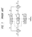
- each optical node includes a communication control circuit 1 of the token passing scheme, a communication control circuit 2 of a demand-assign wavelength-division multiplexing access scheme, a wavelength tunable filter 3 for extracting an optical signal having an arbitrary wavelength from optical signals of a plurality of wavelengths, an O/E converter 4 for converting an optical signal into an electrical signal, a tunable E/O converter 5 for converting an electrical signal into an optical signal having an arbitrary wavelength, an optical or electric receiver 6, an optical or electric transmitter 7, a coupler 8 for branching an optical signal, a coupler 9 for merging optical signals, an optical demultiplexer 10 for separating a signal having a specific wavelength from signals of a plurality of wavelengths, and allowing the signals of the remaining wavelengths to pass therethrough, and a multiplexer 11 for sending optical signals having different wavelengths onto one transmission path.
- a communication control circuit 1 of the token passing scheme includes a communication control circuit 2 of a demand-assign wavelength-division multiplexing access scheme,
- the wavelength tunable filter 3 is an element or a device capable of changing the passing wavelength in accordance with the value of a current flowing in a wavelength control terminal.
- a filter having a DFB (distributed feed back) laser structure can be used as the wavelength tunable filter 3.
- the tunable E/O converter 5 is an element or a device capable of changing the oscillation wavelength in accordance with the value of a current flowing in the wavelength control terminal.
- a DFB laser or a DBR (distributed Bragg reflection) laser can be used as the tunable E/O converter 5.
- a PIN-PD photodiode
- APD avalanche photodiode
- the optical receiver 6 uses an O/E converter
- the optical transmitter 7 uses an E/O converter.
- each solid line indicates an optical transmission path or an optical signal
- each broken line an electrical transmission path or an electrical signal.
- Fig. 7 shows the first embodiment of the network arrangement of the communication system. In this arrangement, a plurality of nodes are connected to a loop type network through couplers, demultiplexers, and multiplexers.
- a communication operation will be described next. Assume that a video signal is being communicated from a node 22 to a node 25 by using the wavelength ⁇ 1, and a file with a large quantity of information is being transmitted from a node 24 to a node 26 by using a wavelength ⁇ 3. In this case, when video communication is to be performed from a node 21 to the node 25, a communication operation is performed in the following manner.
- the node 21 acquires a token by the token passing scheme to acquire a video transmission right and perform line assignment.
- a signal called a token which gives a data transmission right, is circulated in the network.
- a node Upon reception of the token, a node outputs a self-address, a destination address, and data, in the form of a packet signal, to an optical transmission path 20.
- Each node checks whether the destination address coincides with the self-address. If they coincide with each other, the node receives the signal. Communication is performed in this manner.
- the token shown in Fig. 3 has a wavelength ⁇ a and circulates in one direction in the ring-like network.
- the token is extracted by separating it from optical signals of other wavelengths through the optical demultiplexer 10. The token is then regenerated/relayed to be sent onto the optical transmission path 20 through the multiplexer 11.
- the node 21 extracts the token by separating it from optical signals of other wavelengths ( ⁇ 1 and ⁇ 3) through the optical demultiplexer 10.
- the token is then received by the optical receiver 6 and is loaded in the communication control circuit 1 of the token passing Ring scheme.
- the communication control circuit 1 checks whether any free wavelengths are present in the line management table WC of the token, and selects a wavelength which is not in use. For example, in the case shown in Fig. 6A, since the wavelengths ⁇ 1 and ⁇ 3 are in use (the bits assigned to the wavelengths ⁇ 1 and ⁇ 3 are set to "1"), a wavelength ⁇ 2 is selected.
- the node 21 writes the self-address, the address of the destination node 25, and information indicating the selected wavelength ⁇ 2 in a packet, and outputs the packet upon converting it into an optical signal having the wavelength ⁇ a through the optical transmitter 7.
- the optical signal is then sent onto the optical transmission path 20 through the multiplexer 11.
- the line management table WC of the token is updated (setting the bit assigned to the wavelength ⁇ 2 to "1"), as shown in Fig. 6B.
- the line management table WC is converted into an optical signal having the wavelength ⁇ a .
- the optical signal is then output after the above-mentioned packet.
- the communication control circuit 1 informs the set wavelength ⁇ 2 to the communication control circuit 2 of the demand-assign wavelength-division multiplexing access scheme.
- the communication control circuit 2 controls the tunable E/O converter 5 to set the transmission wavelength to ⁇ 2.
- the communication control circuit 2 controls the wavelength tunable filter 3 to set the passing wavelength to ⁇ 2, and informs the completion of a preparation for reception to the communication control circuit 1 of the token passing ring scheme.
- the communication control circuit 1 Upon acquiring the token, the communication control circuit 1 writes the address of the self-node 25, address of the destination node 21, and transmission request data in a packet, and converts the packet into an optical signal having the wavelength ⁇ a through the optical transmitter 7. The optical signal is then sent to the optical transmission path 20 through the multiplexer 11.
- the packet is input to the communication control circuit 1 of the node 21 through the node 26.
- the communication control circuit 1 sends the transmission request to the terminal to cause it to start transmission of the video data.
- video lines are formed into a star network, and control lines through which a wavelength control signal are transmitted are formed into a loop type network.
- a wavelength control signal an optical signal or an electrical signal may be used.
- the wavelength control signal is an optical signal
- an optical transmission path may be used as a transmission path 30, and an optical receiver and an optical transmitter may be used as a receiver 6 and a transmitter 7 of each node, respectively.
- the wavelength control signal is an electrical signal
- an electrical transmission path may be used as the transmission path 30, and an electric receiver and an electric transmitter may be used as the receiver 6 and the transmitter 7, respectively.
- a communication operation will be described next. Similar to the first embodiment, assume that a video signal is being communicated from the node 42 to the node 45 by using a wavelength ⁇ 1, and a file with a large quantity of data is being transmitted from the node 44 to the node 46 by using a wavelength ⁇ 3. In this case, when video communication is to be performed from the node 41 to the node 45, a communication operation is performed in the following manner. Similar to the first embodiment, line assignment is performed through a loop type control line, and video communication from the node 41 to the node 45 is performed by using a wavelength ⁇ 2.
- the reception wavelength of the wavelength tunable filter 3 has already been set to ⁇ 2, only the video signal having the wavelength ⁇ 2 passes through the wavelength tunable filter 3 and is converted into an electrical signal by an O/E converter 4 to be received. Since the filters 3 of the remaining nodes are not set, the video signal is not received.
- the communication is finished in the same manner as in the first embodiment.
- the node 41 extracts the token, and updates a line management table WC.
- the node 45 cancels the setting of the wavelength tunable filter 3 and finishes the communication.
- Fig. 10 shows the network arrangement of the fourth embodiment of the communication system of the present invention.
- this network arrangement includes a coupler for bidirectional transmission 14 and nodes 51 to 56, each identical to the node shown in Fig. 5.
- the same reference numerals in the fourth embodiment denote the same parts as in the above-described embodiment.
- video lines are formed into a bus type network, and control lines are formed into a loop type network.
- a wavelength control signal an optical signal or an electrical signal may be used.
- the wavelength control signal is an optical signal
- an optical transmission path may be used as a transmission path 30, and an optical receiver and an optical transmitter may be used as a receiver 6 and a transmitter 7 of each node, respectively.
- the wavelength control signal is an electrical signal
- an electrical transmission path may be used as the transmission path 30, and an electric receiver and an electric transmitter may be used as the receiver 6 and the transmitter 7, respectively.
- the communication is finished in the same manner as in the first embodiment.
- the node 51 extracts the token, and updates a line management table WC.
- the node 55 cancels the setting of the wavelength tunable filter 3 and finishes the communication.
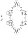
- Fig. 11 shows the network arrangement of the fifth embodiment of the communication system of the present invention.
- this network arrangement includes nodes 61 to 66, each identical to the node shown in Fig. 5.
- the same reference numerals in the fifth embodiment denote the same parts as in the above-described embodiment.
- video lines are formed into a bus type network
- control lines are formed into a loop type network. These networks are accommodated in one optical transmission path through optical demultiplexers 10 and multiplexers 11. In this arrangement, the same operation as that in the fourth embodiment is performed.
- the wavelength control signal is an optical signal
- an optical transmission path is used as a transmission path 20
- an optical receiver and an optical transmitter are respectively used as a receiver 6 and a transmitter 7.
- Fig. 12 shows the network arrangement of the sixth embodiment of the communication system of the present invention.
- this network arrangement includes nodes 71 to 76, each identical to the node shown in Fig. 5.
- the same reference numerals in the fifth embodiment denote the same parts as in the above-described embodiment.
- both a set of video lines and a set of control lines are formed into bus type networks and are accommodated in one optical transmission path. In this arrangement, the same operation as that in the first embodiment is performed.
- a control line protocol is of a token passing bus scheme
- a circuit 1 in each node is a communication control circuit of the token passing scheme.
- the wavelength control signal is an optical signal
- an optical transmission path is used as a transmission path 20
- an optical receiver and an optical transmitter are respectively used as a receiver 6 and a transmitter 7.
- part of the token is branched by a coupler 14 and is separated from optical signals having other wavelengths by a demultiplexer 10 to be extracted.
- the node 71 Upon reception of the token through an optical receiver 6, the node 71 causes the communication control circuit 1 of the token passing bus scheme to check whether any free wavelengths are present in a wavelength table WC of the token, and selects a wavelength which is not used. In this case, since the wavelengths ⁇ 1 and ⁇ 3 are in use (the bits assigned to the wavelengths ⁇ 1 and ⁇ 3 are set to "1"), a wavelength ⁇ 2 is selected.
- the node 71 then writes the address of the self-node 71, the address of the destination node 75, and the information indicating the selected wavelength ⁇ 2 in a packet, and outputs the packet upon converting it into an optical signal having the wavelength ⁇ a through an optical transmitter 7.
- the optical signal is sent to the optical transmission path 20 through a multiplexer 11 and the coupler 14.
- the node 71 updates the line management table WC of the token (sets the bit assigned to the wavelength ⁇ 2 to "1"), and converts the token into an optical signal having the wavelength ⁇ a in the same manner as described above.
- This optical signal is transmitted after the packet.
- the communication control circuit 1 of the token passing bus scheme informs the set wavelength ⁇ 2 to a communication control circuit 2 of the demand-assign wavelength-division multiplexing access scheme.
- the communication control circuit 2 then controls a tunable E/O converter 5 to set the wavelength ⁇ 2.
- the communication control circuit 1 of the token passing bus scheme Upon acquiring the token, the communication control circuit 1 of the token passing bus scheme writes self-address 75, destination address 71, and transmission request data in a packet, and converts the packet into an optical signal having the wavelength ⁇ a through the optical transmitter 7. The optical signal is then sent to the optical transmission path 20 through the multiplexer 11 and the coupler 14. The packet passes through the optical transmission path 20 and is input to the communication control circuit 1 of the node 71.
- the communication control circuit 1 of the node 71 supplies the transmission request to a terminal to cause it to start transmission of a video signal.
- the tunable E/O converter 5 converts the video signal into an optical signal having the wavelength ⁇ 2, and outputs it from the node 71.
- the signals with large quantities of data, having the wavelengths ⁇ 2 and ⁇ 3, are currently transmitted in the network.
- these optical signals are extracted through the coupler 14 and the optical demultiplexer 10. Since the reception wavelength of a wavelength tunable filter 3 of the node 75 has already been set to ⁇ 2, only the video signal having the wavelength ⁇ 2 passes through the wavelength tunable filter 3 and is converted into an electrical signal by an O/E converter 4 to be received. Since the filters 3 of the remaining nodes are not set, no signal with a large quantity of data is received by these nodes.
- the communication is finished in the same manner as in the first embodiment.
- the node 71 extracts the token, and updates a line management table WC.
- the node 75 cancels the setting of the wavelength tunable filter 3 and finishes the communication.
- an optical transmission path may be used as a transmission path 30; an optical receiver and an optical transmitter may be used as a receiver 6 and a transmitter 7 of each node, respectively; and an optical coupler for bidirectional transmission may be used as the coupler 15.
- an electrical transmission path may be used as the transmission path 30; an electric receiver and an electric transmitter may be used as the receiver 6 and the transmitter 7, respectively; and an electrical coupler for bidirectional transmission may be used as the coupler 15.
- Fig. 14 shows the network arrangement of the eighth embodiment of the communication system of the present invention.
- this network arrangement includes nodes 91 to 96, each identical to that shown in Fig. 5.
- the same reference numerals in the eighth embodiment denote the same parts as in the above-described embodiment.
- video lines are formed into a star network to perform the same operation as the star type video line network in the third embodiment
- control lines are formed into a bus type network to perform the same operation as that of the bus type control line network in the seventh embodiment.
- a wavelength control signal an optical signal or an electrical signal may be used.
- an optical transmission path may be used as a transmission path 30; an optical receiver and an optical transmitter may be used as a receiver 6 and a transmitter 7 of each node, respectively; and an optical coupler for bidirectional transmission may be used as a coupler 15.
- an electrical transmission path may be used as the transmission path 30; an electric receiver and an electric transmitter may be used as the receiver 6 and the transmitter 7, respectively; and an electrical coupler for bidirectional transmission may be used as the coupler 15.
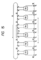
- Fig. 15 shows the network arrangement of the ninth embodiment of the communication system of the present invention.
- this network arrangement includes nodes 101 to 106, each identical to that shown in Fig. 5.
- the same reference numerals in the ninth embodiment denote the same parts as in the above-described embodiment.
- video lines are formed into a loop type network to perform the same operation as the loop type video line network in the second embodiment
- control lines are formed into a bus type network to perform the same operation as that of the bus type control line network in the seventh embodiment.
- a wavelength control signal an optical signal or an electrical signal may be used.
- an optical transmission path may be used as a transmission path 30; an optical receiver and an optical transmitter may be used as a receiver 6 and a transmitter 7 of each node, respectively; and an optical coupler for bidirectional transmission may be used as a coupler 15.
- an electrical transmission path may be used as the transmission path 30; an electric receiver and an electric transmitter may be used as the receiver 6 and the transmitter 7, respectively; and an electrical coupler for bidirectional transmission may be used as the coupler 15.
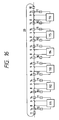
- Fig. 16 shows the network arrangement of the tenth embodiment of the communication system of the present invention.
- this network arrangement includes nodes 111 to 116, each identical to that shown in Fig. 5.
- the same reference numerals in the tenth embodiment denote the same parts as in the above-described embodiment.
- video lines are formed into a loop type network
- control lines are formed into a bus type network. These networks are accommodated in one optical transmission path 20 through couplers 14 and couplers 8 and 9.
- control signal is an optical signal
- an optical receiver and an optical transmitter may be used as a receiver 6 and a transmitter 7 of each node, respectively.
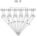
- Fig. 17 shows the network arrangement of the eleventh embodiment of the communication system of the present invention.
- this network arrangement includes an optical or electrical star coupler 110 and nodes 121 to 126, each identical to that shown in Fig. 5.
- the same reference numerals in the eleventh embodiment denote the same parts as in the above-described embodiment.
- video lines are formed into a bus type network, and control lines are formed into a star type network.
- the same operation as that in the first embodiment is performed.
- a wavelength control signal an optical signal or an electrical signal may be used.
- an optical transmission path may be used as a transmission path 30; an optical receiver and an optical transmitter may be used as a receiver 6 and a transmitter 7 of each node, respectively; and an optical star coupler may be used as the star coupler 110.
- an electrical transmission path may be used as the transmission path 30; an electric receiver and an electric transmitter may be used as the receiver 6 and the transmitter 7, respectively; and an electrical star coupler may be used as the star coupler 110.
- a communication operation will be described next. Similar to the first embodiment, assume that a video signal is being communicated from the node 122 to the node 125 by using a wavelength ⁇ 1, and a file with a large quantity of data is being transmitted from the node 124 to the node 126 by using a wavelength ⁇ 3.
- a communication operation is performed in the following manner.
- the node 121 acquires a token by the token passing bus scheme. The token circulates in the star type network in a predetermined order. Upon reception of the token, each node reproduces/relays the token and outputs it to the next node.
- the node 121 Upon reception of the token through an optical receiver 6, the node 121 causes the communication control circuit 1 of the token passing bus scheme to check whether any free wavelengths are present in a wavelength table WC of the token, and selects a wavelength which is not used. In this case, since the wavelengths ⁇ 1 and ⁇ 3 are in use (the bits assigned to the wavelengths ⁇ 1 and ⁇ 3 are set to "1"), a wavelength ⁇ 2 is selected. The node 121 then writes the address of the self-node 121, the address of the destination node 125, and the information indicating the selected wavelength ⁇ 2 in a packet, and outputs the packet from the transmitter 7 to the transmission path 30. In addition, the node 121 updates the line management table WC of the token (sets the bit assigned to the wavelength ⁇ 2 to "1"), and transmits it after the packet.
- the communication control circuit 1 of the token passing bus scheme informs the set wavelength ⁇ 2 to a communication control circuit 2 of the demand-assign wavelength-division multiplexing access scheme.
- the communication control circuit 2 then controls a tunable E/O converter 5 to set the wavelength ⁇ 2.
- the packet sent from the node 121 is input to the node 125 through the star coupler 110.
- the packet is then loaded in the communication control circuit 1.
- the communication control circuit 1 reads the destination address in the packet.
- the communication control circuit 1 informs the reception wavelength written in the packet to the communication control circuit 2 of the wavelength-division multiplexing access scheme. Since the node 125 is receiving the video signal from the node 122, the node 125 maintains the current setting of a filter 3 until the communication is finished. Instead of this operation, the node 125 may inform the node 121 that reception is being performed.
- the communication control circuit 2 of the node 125 controls the wavelength tunable filter 3 to set the passing wavelength to ⁇ 2, and informs the completion of a preparation for reception to the communication control circuit 1 of the token passing bus scheme.
- the communication control circuit 1 of the token passing bus scheme Upon acquiring the token, the communication control circuit 1 of the token passing bus scheme writes the address of the self-node 125, the address of the destination node 121, and transmission request data in a packet, and sends it to the optical transmission path 30 through the transmitter 7.
- the packet passes through the star coupler 110 and is input to the communication control circuit 1 of the node 121.
- the communication control circuit 1 of the node 121 supplies the transmission request to a terminal to cause it to start transmission of a video signal.
- Fig. 18 shows the network arrangement of the twelfth embodiment of the communication system of the present invention.
- this network arrangement includes nodes 131 to 136, each identical to that shown in Fig. 5.
- the same reference numerals in the twelfth embodiment denote the same parts as in the above-described embodiment.
- video lines are formed into a loop type network to perform the same operation as that of the loop type video line network in the second embodiment, and control lines are formed into a star type network to perform the same operation as that of the star type control line network in the eleventh embodiment.
- a wavelength control signal an optical signal or an electrical signal may be used.
- Fig. 19 shows the network arrangement of the thirteenth embodiment of the communication system of the present invention.
- this network arrangement includes nodes 141 to 146, each identical to the node shown in Fig. 5.
- the same reference numerals in the thirteenth embodiment denote the same parts as in the above-described embodiment.
- both a set of video lines and a set of control lines are formed into a star type network and are accommodated in one optical transmission path 20 through demultiplexers 10 and multiplexers 11.
- the same operation as that in the fourth embodiment is performed.
- the operation of the video line network is performed in the same manner as in the third embodiment, and the operation of the control line network is performed in the same manner as in the twelfth embodiment.
- the wavelength control signal is an optical signal
- an optical transmission path is used as a transmission path 20
- an optical receiver and an optical transmitter are respectively used as a receiver 6 and a transmitter 7.
- an optical transmission path may be used as a transmission path 30; an optical receiver and an optical transmitter may be used as a receiver 6 and a transmitter 7 of each node, respectively; and an optical star coupler may be used as a star coupler 110.
- an electrical transmission path may be used as the transmission path 30; an electric receiver and an electric transmitter may be used as the receiver 6 and the transmitter 7, respectively; and an electrical star coupler may be used as the star coupler 110.
- the communication scheme is not limited to the token passing scheme.
- the present invention can be applied to a scheme of inserting information in a fixed-length time slot, e.g., a slotted ring or slotted bus scheme.
- a line management table is arranged in part of a fixed-length time slot, and a function of relaying a line management table is arranged between a node for generating a slot and a node for terminating the slot.
- Fig. 21 shows the second embodiment of the node used in the present invention.
- Fig. 22 shows the network arrangement of the fifteenth embodiment of the communication system of the present invention.
- each node includes a communication control circuit 301 of a DQDB (distributed queued dual bus) scheme, a communication control circuit 302 of the demand-assign wavelength-division multiplexing access (DA-WDMA) scheme, a wavelength tunable filter 303 for extracting an optical signal having an arbitrary wavelength from optical signals having a plurality of wavelengths, an O/E converter 304 for converting an optical signal into an electrical signal, a tunable E/O converter 305 for converting an electrical signal into an optical signal having an arbitrary wavelength, optical or electrical receivers 306 and 309, and optical or electrical transmitters 307 and 308.
- DQDB distributed queued dual bus
- DA-WDMA demand-assign wavelength-division multiplexing access
- the network includes couplers 214, an optical transmission path 220, slot generators 221 and 227 for generating frame pulses, nodes 222 to 226, each identical to that shown in Fig. 21, and optical or electrical transmission paths 230 constituting a composite arrangement of a DQDB line and a bus type wavelength-division multiplexing line.
- a signal with a large quantity of data e.g., a video signal, which is difficult to transmit through the DQDB line
- other signals e.g., a data signal and a control signal
- slots each containing information are transmitted from the slot generators 221 and 227, arranged on the two ends of each of two buses, in opposite directions.
- the number of nodes, on the upstream side, from which transmission requests are generated is known from the number of request bits on one bus.
- a wavelength management table indicating used wavelengths is circulated through the DQDB line, and a node which extracts the wavelength management table selects a free wavelength, updates the wavelength management table, and sends the table to the transmission path 230.
- the wavelength management table is constituted by bits larger in number than the wavelengths used in the network. In the table, each bit is assigned to a wavelength to indicate whether the wavelength is in use. If a wavelength ⁇ 1 is in use, the bit assigned to the wavelength ⁇ 1 is set to "1".
- the bit is set to "0". If, for example, it is determined in advance that the wavelength management table is arranged in a slot following a frame pulse, each node can recognize the wavelength management table from the position of the frame pulse. In the DQDB scheme, since a double bus arrangement is employed, the wavelength management table transmitted through one bus is returned by one slot generator to be inserted in a slot following a frame pulse of the other bus, and the wavelength management table is transmitted upon setting a busy bit to "1" indicating that the slot is being used.
- a communication operation will be described next. Assume that a video signal is being communicated from the node 223 to the node 225 by using a wavelength ⁇ 1, and a file with a large quantity of data is being transmitted from the node 224 to the node 226 by using a wavelength ⁇ 3.
- a communication operation is performed in the following manner. First, in the DQDB line, the node 222 performs assignment of wavelengths to be used in the wavelength-division multiplexing line. Upon reception of the wavelength management table, the node 222 selects a wavelength which is not used, updates the wavelength management table, and sends it to the transmission path 230.
- wavelengths ⁇ 1 and ⁇ 3 are in use (the bits assigned to the wavelengths ⁇ 1 and ⁇ 3 are set to "1"), a wavelength ⁇ 2 is selected. The bit assigned to the wavelength ⁇ 2 is then set to "1" and sent to the transmission path 230.
- the node 222 then outputs a transmission request through the transmitter 308, and lets slots, input to the receiver 306, pass by until the value of a counter in the communication control circuit 301 of the DQDB scheme becomes "0".
- the node 222 writes the self-address, the address of the destination node 225, and information indicating the selected wavelength ⁇ 2 in a slot, and outputs the slot to the transmission path 230 through the transmitter 307.
- the communication control circuit 301 of the DQDB scheme informs the set wavelength ⁇ 2 to the communication control circuit 302 of the demand-assign wavelength-division multiplexing access scheme.
- the communication control circuit 302 of the DA-WDMA scheme controls the tunable E/O converter 305 to set the transmission wavelength to wavelength ⁇ 2.
- the slot sent from the node 222 is input to the node 225 through the nodes 223 and 224.
- the slot is then received by the receiver 306 and is loaded in the communication control circuit 301.
- the communication control circuit 301 of the DQDB scheme reads the destination address.
- the communication control circuit 301 informs the written reception wavelength to the communication control circuit 302 of the DA-WDMA scheme. Since the node 225 is receiving the video signal from the node 223, the communication control circuit 302 of the DA-WDMA scheme maintains the setting of the filter 303 until the communication is finished. Instead of this operation, the node 225 may inform the node 222 that reception is being performed.
- the communication control circuit 302 of the DA-WDMA scheme controls the wavelength tunable filter 303 to set the passing wavelength to ⁇ 2, and informs the completion of a preparation for reception to the communication control circuit 301 of the DQDB scheme.
- the communication control circuit 301 of the DQDB scheme outputs a transmission request through the transmitter 307.
- the communication control circuit 301 writes the address of the self-node 225, the address of the destination address 222, and the transmission request data for the video signal in the slot input to the receiver 309, and sends the slot to the transmission path 230 through the transmitter 308.
- the slot is input to the node 222 through the nodes 224 and 223.
- the slot is then received by the receiver 309 and is loaded in the communication control circuit 301.
- the DQDB scheme communication control circuit 301 of the node 222 sends the transmission request to a terminal to cause the terminal to start transmission of the video signal.
- the E/O converter 305 converts the video signal into an optical signal having the wavelength ⁇ 2 and outputs the signal.
- the optical signal is sent to the optical transmission path 220 through the coupler 214.
- the optical signal is transmitted in two directions through the optical transmission path 220. Part of the signal is branched by the coupler 214 in each node to be extracted, while the remaining portion of each signal passes through the coupler 214 to be transmitted to a corresponding end of the optical transmission path 220. Consequently, the signals with large quantities of data, having the wavelengths ⁇ 2 and ⁇ 3, are currently transmitted through the transmission path 220. Since the reception wavelength of the wavelength tunable filter 303 of the node 225 has already been set to ⁇ 2, only the video signal having the wavelength ⁇ 2 passes through the wavelength tunable filter 303 and is converted into an electrical signal by the O/E converter 304 to be received. Although the video signal is extracted by the remaining nodes, the signal is not received because the filters 303 are not set.
- the node 222 extracts the wavelength management table, and updates it. In this case, the bit assigned to the wavelength ⁇ 2 is set to "0", and the wavelength management table is sent to the transmission path 230. If the end of the communication needs to be informed to the node 225, the node 222 informs it through the DQDB line. When a video signal is not received for a predetermined period of time or more, or when information indicating the end of the communication is received, the node 225 cancels the setting of the wavelength tunable filter 303 and finishes the communication.
- Fig. 23 shows the network arrangement of the sixteenth embodiment of the communication system of the present invention.
- this network arrangement includes couplers 213, each serving to branch an optical signal, couplers 212, each serving to merge optical signals, and nodes 231 to 235 each identical to that shown in Fig. 21.
- the same reference numerals in the sixteenth embodiment denote the same parts as in the fifteenth embodiment.
- a DQDB line and a loop type wavelength-division multiplexing line are formed into a composite arrangement, and the same operation as that in the fifteenth embodiment is performed.
- a communication operation will be described next. Assume that a video signal is being communicated from the node 233 to the node 235 by using a wavelength ⁇ 1, and a file with a large quantity of data is being transmitted from the node 234 to the node 231 by using a wavelength ⁇ 3.
- a communication operation is performed in the following manner. Similar to the fifteenth embodiment, in the DQDB line, assignment of wavelengths to be used in the wavelength-division multiplexing line is performed, and video communication from the node 232 to the node 235 is performed by using a wavelength ⁇ 2.
- an E/O converter 305 converts the video signal into an optical signal having the wavelength ⁇ 2.
- the optical signal is output from the node 232 to an optical transmission path 220.
- This optical signal is sent to the optical transmission path 220 through the coupler 212 and is transmitted on the optical transmission path 220 through the couplers 213 and 212 connected thereto.
- part of the optical signal is branched to be extracted through the coupler 213, but the remaining portion is caused to pass therethrough.
- the signals with large quantities of data, having the wavelengths ⁇ 2 and ⁇ 3, are currently transmitted through the transmission path 220.
- the video signal having the wavelength ⁇ 2 passes through a wavelength tunable filter 303, since the reception wavelength of the wavelength tunable filter 303 has already been set to ⁇ 2.
- the video signal is then converted into an electrical signal by an O/E converter 304 to be received.
- the video signal is extracted by the remaining nodes, the signal is not received because the filters 303 are not set.
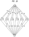
- Fig. 24 shows the network arrangement of the seventeenth embodiment of the communication system of the present invention.
- this network arrangement includes a star coupler 240 and nodes 241 to 245, each identical to that shown in Fig. 21.
- the same reference numerals in the seventeenth embodiment denote the same parts as in the fifteenth embodiment.
- a DQDB line and a star type wavelength-division multiplexing line are formed into a composite arrangement, and the same operation as that in the fifteenth embodiment is performed.
- a communication operation will be described next. Assume that a video signal is being communicated from the node 243 to the node 241 by using a wavelength ⁇ 1, and a file with a large quantity of data is being transmitted from the node 244 to the node 241 by using a wavelength ⁇ 3.
- a communication operation is performed in the following manner. Similar to the fifteenth embodiment, in the DQDB line, assignment of wavelengths to be used in the wavelength-division multiplexing line is performed, and video communication from the node 242 to the node 245 is performed by using the a wavelength ⁇ 2.
- an E/O converter 305 converts the video signal into an optical signal having the wavelength ⁇ 2.
- the optical signal is output from the node 242 to an optical transmission path 220.
- This optical signal is equally branched by the coupler 240 to be distributed to all the nodes through the optical transmission path 220. Consequently, the signals with large quantities of data, having the wavelengths ⁇ 2 and ⁇ 3, are currently transmitted through the transmission path 220.
- the video signal having the wavelength ⁇ 2 passes through a wavelength tunable filter 303, since the reception wavelength of the wavelength filter 303 has already been set to ⁇ 2.
- the video signal is then converted into an electrical signal by an O/E converter 304 to be received. Although the video signal is extracted by the remaining nodes, the signal is not received because the filters 303 are not set.
- the communication is finished in the same manner as in the fifteenth embodiment.
- the node 242 extracts a wavelength management table, and updates the line management table.
- the node 245 cancels the setting of the wavelength tunable filter 303 and finishes the communication.
- a DQDB line and a wavelength-division multiplexing line are separated from each other.
- optical signal wavelengths in a DQDB line may be set to be different from those used in a wavelength-division multiplexing line so that both the lines may be accommodated in one transmission path by using multiplexers and demultiplexers.
- the wavelength-division multiplexing line is used to transmit a continuous signal such as a video signal.
- the use of the wavelength-division multiplexing line is not limited to this.
- the line may be used to transmit a time-division multiplexing signal or a packet signal.
- the transmission section transmits a signal to the wavelength-division multiplexing line after performing assignment of a wavelength to be used and a time slot to be used in the DQDB line.
- the reception section controls the wavelength tunable filter 3 through the communication control circuit 2 of the DA-WDMA scheme to receive a signal having an arbitrary wavelength and an arbitrary time slot.
- a communication network may be constituted by a signal line of the DQDB scheme and a line including a time-division multiplexing signal or a packet signal, and a line assignment table having information indicating the used states of slots may be arranged in a signal line slot.
- a node which extracts the line assignment table selects a time slot which is not in use to perform assignment of a time slot to be used, and updates the line assignment table, which is circulated in the network.
- the transmission section transmits a signal to the time-division multiplexing line after performing assignment of a time slot to be used in the DQDB line.
- the reception section can receive a signal having an arbitrary time slot by controlling the filter through the communication control circuit of the TDMA scheme.
- a line management table for wavelength- and time-division multiplexing communication is circulated in a network, and each node which extracts the line management table performs line assignment to determine a communication line. With this operation, no line management node is required, and the procedure for communication can be simplified.
- a communication system includes a plulrality of nodes, a data signal line and a control signal line.
- the plurality of nodes are coupled each other through the data signal line so as to perform communication by using a signal multiplexed by at least one of a wavelength-division multiplexing scheme and a time-division multiplexing scheme.
- the plurality of nodes are coupled each other through the control signal line by which a control signal including a management table indicative of at lease one of a time slot and a wavelength of a signal used for communication in the data signal line is circulated.
- Each node inputs a control signal circulating through the control signal line to select at least one of a time slot and a wavelength of a signal not used for communication on the basis of the management table of the input control signal, so that the communication is performed through the data signal line by using at least selected one of the time slot and the wavelength of the signal and the management table is updated to be outputted to the control signal line.
Applications Claiming Priority (6)
| Application Number | Priority Date | Filing Date | Title |
|---|---|---|---|
| JP33002392A JPH06164610A (ja) | 1992-11-16 | 1992-11-16 | 回線割り当て方法およびそれを用いた波長多重通信システム |
| JP330023/92 | 1992-11-16 | ||
| JP33002392 | 1992-11-16 | ||
| JP35464692A JP3292390B2 (ja) | 1992-12-16 | 1992-12-16 | 通信装置及びその制御方法 |
| JP354646/92 | 1992-12-16 | ||
| JP35464692 | 1992-12-16 |
Publications (2)
| Publication Number | Publication Date |
|---|---|
| EP0599177A1 true EP0599177A1 (de) | 1994-06-01 |
| EP0599177B1 EP0599177B1 (de) | 2002-05-29 |
Family
ID=26573399
Family Applications (1)
| Application Number | Title | Priority Date | Filing Date |
|---|---|---|---|
| EP93118462A Expired - Lifetime EP0599177B1 (de) | 1992-11-16 | 1993-11-15 | Übertragungsverfahren und -system mit Tokenübergabezugriffsprotokoll |
Country Status (6)
| Country | Link |
|---|---|
| US (1) | US5500857A (de) |
| EP (1) | EP0599177B1 (de) |
| AT (1) | ATE218257T1 (de) |
| AU (1) | AU5073993A (de) |
| CA (1) | CA2103112A1 (de) |
| DE (1) | DE69331965D1 (de) |
Cited By (6)
| Publication number | Priority date | Publication date | Assignee | Title |
|---|---|---|---|---|
| EP0869634A2 (de) * | 1997-03-05 | 1998-10-07 | Fujitsu Limited | Wellenlängen-Multiplexing in passiven optischen Netzwerken |
| GB2329291A (en) * | 1997-09-12 | 1999-03-17 | Samsung Electronics Co Ltd | Wavelength allocation in an optical fibre subscriber network |
| WO1999037050A1 (en) * | 1998-01-03 | 1999-07-22 | British Telecommunications Public Limited Company | Communications system with star/ring topology |
| CN1048840C (zh) * | 1996-05-24 | 2000-01-26 | 北京大学 | 用电话网或计算机互连网管理数据网的方法 |
| EP1227610A2 (de) * | 2001-01-25 | 2002-07-31 | Alcatel | Verteilte intelligente MAC-Protokolle für DWDM-Ringnetze |
| EP1386434A2 (de) * | 2001-04-20 | 2004-02-04 | Intel Corporation | Optische verbindung mehrerer prozessoren |
Families Citing this family (31)
| Publication number | Priority date | Publication date | Assignee | Title |
|---|---|---|---|---|
| JP3262453B2 (ja) * | 1994-05-13 | 2002-03-04 | キヤノン株式会社 | 情報共有方法及び回線割当方法及びそれを用いた通信システム |
| SE503258C2 (sv) * | 1995-02-06 | 1996-04-29 | Ericsson Telefon Ab L M | Förfarande för tilldelning av våglängdskanaler i ett optiskt bussnät |
| US5936960A (en) * | 1997-03-07 | 1999-08-10 | Advanced Micro Devices, Inc. | Apparatus for and method of communicating among devices interconnected on a bus |
| US5898801A (en) * | 1998-01-29 | 1999-04-27 | Lockheed Martin Corporation | Optical transport system |
| US6631018B1 (en) | 1997-08-27 | 2003-10-07 | Nortel Networks Limited | WDM optical network with passive pass-through at each node |
| JP2955555B1 (ja) * | 1998-02-13 | 1999-10-04 | 松下電器産業株式会社 | ネットワークシステム |
| JP3586603B2 (ja) * | 1999-11-25 | 2004-11-10 | Necエレクトロニクス株式会社 | データ転送装置及びデータ転送方法 |
| US7006434B1 (en) * | 2000-02-10 | 2006-02-28 | Ciena Corporation | System for non-disruptive insertion and removal of nodes in an ATM sonet ring |
| JP4304821B2 (ja) * | 2000-04-05 | 2009-07-29 | 沖電気工業株式会社 | ネットワークシステム |
| US6694100B1 (en) * | 2000-06-05 | 2004-02-17 | Lucent Technologies Inc. | Space wavelength time-division multiple access optical transmission system |
| US6925259B2 (en) * | 2000-10-12 | 2005-08-02 | At&T Corp. | MAC protocol for optical packet-switched ring network |
| US7085494B2 (en) | 2000-10-12 | 2006-08-01 | At & T Corp. | High-capacity packet-switched ring network |
| US20020101874A1 (en) * | 2000-11-21 | 2002-08-01 | Whittaker G. Allan | Physical layer transparent transport information encapsulation methods and systems |
| US7009991B2 (en) * | 2002-03-28 | 2006-03-07 | Matisse Networks | Reservation-based media access controller and reservation-based optical network |
| US7085497B2 (en) * | 2002-04-03 | 2006-08-01 | Lockheed Martin Corporation | Vehicular communication system |
| US20040076434A1 (en) * | 2002-09-27 | 2004-04-22 | Whittaker G. Allan | Optical distribution network for RF and other analog signals |
| US6912339B2 (en) | 2002-09-27 | 2005-06-28 | Lockheed Martin Corporation | Optical interface devices having balanced amplification |
| US7283480B1 (en) | 2002-11-12 | 2007-10-16 | Lockheed Martin Corporation | Network system health monitoring using cantor set signals |
| US7349629B1 (en) | 2002-11-26 | 2008-03-25 | Lockheed Martin Corporation | Methods and systems for creating a digital interconnect fabric |
| US7424228B1 (en) | 2003-03-31 | 2008-09-09 | Lockheed Martin Corporation | High dynamic range radio frequency to optical link |
| WO2004093351A2 (en) * | 2003-03-31 | 2004-10-28 | Lockheed Martin Corporation | Optical network interface systems and devices |
| US20050182639A1 (en) * | 2004-02-18 | 2005-08-18 | Fujitsu Limited | Dynamic virtual organization manager |
| US7965732B2 (en) * | 2004-03-19 | 2011-06-21 | Fujitsu Limited | Scheduling token-controlled data transmissions in communication networks |
| US7529267B2 (en) * | 2004-03-19 | 2009-05-05 | Fujitsu Limited | Data transmissions in communication networks using multiple tokens |
| US7623543B2 (en) * | 2004-03-19 | 2009-11-24 | Fujitsu Limited | Token-controlled data transmissions in communication networks |
| US7440699B1 (en) | 2004-06-28 | 2008-10-21 | Lockheed Martin Corporation | Systems, devices and methods for transmitting and receiving signals on an optical network |
| US20080124081A1 (en) * | 2006-11-27 | 2008-05-29 | Takeo Hamada | Predictive scheduling of data path control |
| US8634430B2 (en) * | 2006-11-27 | 2014-01-21 | Fujitsu Limited | Multicast transmissions in optical burst transport |
| US7826747B2 (en) * | 2006-11-27 | 2010-11-02 | Fujitsu Limited | Optical burst transport using an electro-optic switch |
| US8666248B2 (en) * | 2010-11-01 | 2014-03-04 | Lockheed Martin Corporation | Method for data frame reduction in a photonic-based distributed network switch |
| US9130691B2 (en) * | 2013-02-25 | 2015-09-08 | Verizon Patent And Licensing Inc. | Optical burst switched network nodes |
Citations (2)
| Publication number | Priority date | Publication date | Assignee | Title |
|---|---|---|---|---|
| US4896934A (en) * | 1989-02-03 | 1990-01-30 | Bell Communications Research, Inc. | Broadband optical multicast switch |
| EP0497005A2 (de) * | 1990-12-28 | 1992-08-05 | Nec Corporation | Zugriffsverfahren für optische Nahbereichsnetz-Systeme |
Family Cites Families (1)
| Publication number | Priority date | Publication date | Assignee | Title |
|---|---|---|---|---|
| SE463236B (sv) * | 1989-02-27 | 1990-10-22 | Joing Invest Ab | Stjaernformigt datanaet med logisk ringfunktion utnyttjande foeretraedesvis token-access |
-
1993
- 1993-11-15 CA CA002103112A patent/CA2103112A1/en not_active Abandoned
- 1993-11-15 US US08/151,986 patent/US5500857A/en not_active Expired - Fee Related
- 1993-11-15 DE DE69331965T patent/DE69331965D1/de not_active Expired - Lifetime
- 1993-11-15 EP EP93118462A patent/EP0599177B1/de not_active Expired - Lifetime
- 1993-11-15 AT AT93118462T patent/ATE218257T1/de not_active IP Right Cessation
- 1993-11-16 AU AU50739/93A patent/AU5073993A/en not_active Abandoned
Patent Citations (2)
| Publication number | Priority date | Publication date | Assignee | Title |
|---|---|---|---|---|
| US4896934A (en) * | 1989-02-03 | 1990-01-30 | Bell Communications Research, Inc. | Broadband optical multicast switch |
| EP0497005A2 (de) * | 1990-12-28 | 1992-08-05 | Nec Corporation | Zugriffsverfahren für optische Nahbereichsnetz-Systeme |
Non-Patent Citations (7)
| Title |
|---|
| F.HALSALL ET AL.: "FAMNET: an integrated voice and data network.", IEE PROCEEDINGS E. COMPUTERS & DIGITAL TECHNIQUES, vol. 134, no. 1, 1 January 1987 (1987-01-01), STEVENAGE GB, pages 1 - 8 * |
| J.M. SENIOR ET AL.: "Performance investigation of a token passing access protocol for a multichannel optical fibre LAN", COMPUTER COMMUNICATIONS, vol. 11, no. 6, December 1988 (1988-12-01), GUILDFORD GB, pages 304 - 312, XP026651337, DOI: doi:10.1016/0140-3664(88)90043-6 * |
| JON M. MARK ET AL.: "A dual-ring LAN for integrated voice/video/data services.", PROCEEDINGS INFOCOM '90. CONFERENCE ON COMPUTER COMMUNICATIONS, 3 June 1990 (1990-06-03), SAN FRANCISCO (US), pages 850 - 857, XP000164304 * |
| KWOK-WAI CHEUNG: "Design and Implementation considerations for wavelength-Division multiplexed (WDM) photonic dual bus.", PROCEEDINGS SUPERCOMM /ICC '92. INTERNATIONAL CONFERENCE ON COMMUNICATIONS, 14 June 1992 (1992-06-14), CHICAGO (US), pages 848 - 854, XP000326796 * |
| PATRICK W. DOWD: "High performance interprocessor communication through optical wavelength division multiple access channels.", PROCEEDINGS 18TH ANNUAL INTERNATIONAL SYMPOSIUM ON COMPUTER ARCHITECTURE, 27 May 1991 (1991-05-27), TORONTO (CA), pages 96 - 105 * |
| PETER COCHRANE ET AL.: "Future optical fiber transmission technology and networks.", IEEE COMMUNICATIONS MAGAZINE, vol. 26, no. 11, 1 November 1988 (1988-11-01), NEW YORK (US), pages 45 - 60 * |
| S. SHARROCK ET AL.: "A BROADBAND-BASED INTEGRATED VOICE/DATA/VIDEO NETWORK OF MULTIPLE LANS WITH DYNAMIC BANDWITH ALLOCATION.", PROCEEDINGS IEEE INFOCOM '87. THE CONFERENCE ON COMPUTER COMMUNICATIONS., 31 March 1987 (1987-03-31), SAN FRANCISCO (US), pages 417 - 425 * |
Cited By (12)
| Publication number | Priority date | Publication date | Assignee | Title |
|---|---|---|---|---|
| CN1048840C (zh) * | 1996-05-24 | 2000-01-26 | 北京大学 | 用电话网或计算机互连网管理数据网的方法 |
| EP0869634A2 (de) * | 1997-03-05 | 1998-10-07 | Fujitsu Limited | Wellenlängen-Multiplexing in passiven optischen Netzwerken |
| EP0869634A3 (de) * | 1997-03-05 | 2002-04-17 | Fujitsu Limited | Wellenlängen-Multiplexing in passiven optischen Netzwerken |
| US6411410B1 (en) | 1997-03-05 | 2002-06-25 | Fujitsu Limited | Wavelength-division multiplexing in passive optical networks |
| GB2329291A (en) * | 1997-09-12 | 1999-03-17 | Samsung Electronics Co Ltd | Wavelength allocation in an optical fibre subscriber network |
| GB2329291B (en) * | 1997-09-12 | 2000-03-22 | Samsung Electronics Co Ltd | Optical fibre subscriber network |
| US6445472B1 (en) | 1997-09-12 | 2002-09-03 | Samsung Electronics, Co., Ltd. | Optical fiber subscriber network |
| WO1999037050A1 (en) * | 1998-01-03 | 1999-07-22 | British Telecommunications Public Limited Company | Communications system with star/ring topology |
| EP1227610A2 (de) * | 2001-01-25 | 2002-07-31 | Alcatel | Verteilte intelligente MAC-Protokolle für DWDM-Ringnetze |
| EP1227610A3 (de) * | 2001-01-25 | 2005-09-14 | Alcatel | Verteilte intelligente MAC-Protokolle für DWDM-Ringnetze |
| US7899066B2 (en) | 2001-01-25 | 2011-03-01 | Alcatel Lucent | Distributed intelligence MAC protocols for DWDM ring networks |
| EP1386434A2 (de) * | 2001-04-20 | 2004-02-04 | Intel Corporation | Optische verbindung mehrerer prozessoren |
Also Published As
| Publication number | Publication date |
|---|---|
| ATE218257T1 (de) | 2002-06-15 |
| US5500857A (en) | 1996-03-19 |
| EP0599177B1 (de) | 2002-05-29 |
| AU5073993A (en) | 1994-05-26 |
| DE69331965D1 (de) | 2002-07-04 |
| CA2103112A1 (en) | 1994-05-17 |
Similar Documents
| Publication | Publication Date | Title |
|---|---|---|
| EP0599177B1 (de) | Übertragungsverfahren und -system mit Tokenübergabezugriffsprotokoll | |
| US5369515A (en) | Node for loop-type optical LAN and a loop-type optical LAN using the same | |
| JP3335075B2 (ja) | ネットワークシステム及びノード装置及び伝送制御方法 | |
| EP0497005B1 (de) | Zugriffsverfahren für optische Nahbereichsnetz-Systeme | |
| US5801861A (en) | Communication system for performing wavelength division multiplexing communications, and wavelength control method used in the system | |
| JP3262453B2 (ja) | 情報共有方法及び回線割当方法及びそれを用いた通信システム | |
| EP0781006B1 (de) | Ringnetz mit Wellenlängenmultiplexing | |
| EP0629058B1 (de) | Wellenlängenauswahlsteuerungssystem eines optischen Netzes | |
| EP0658992A1 (de) | Optisches Übertragungssystem | |
| CA2181362C (en) | Interconnected passive optical networks | |
| JP3311234B2 (ja) | ネットワークシステム及びノード装置及び伝送制御方法 | |
| US20020018260A1 (en) | Multimedia optical community area network | |
| US6005862A (en) | Node device used in network system for performing packet communications, network system using the same, and communication method used in the system | |
| US6385206B1 (en) | Communication network and method, and node and exchange node used therein | |
| JP4598934B2 (ja) | 光伝送装置および光伝送システム | |
| JP3292390B2 (ja) | 通信装置及びその制御方法 | |
| JP3332776B2 (ja) | 伝送制御方法及びそれを用いるネットワークシステム | |
| JPS6031131B2 (ja) | 分布形光ネットワ−ク | |
| JPH06164610A (ja) | 回線割り当て方法およびそれを用いた波長多重通信システム | |
| JPH06232885A (ja) | 通信ネットワークシステム | |
| US20040223760A1 (en) | Optical communications access network architecture and method | |
| JP3334967B2 (ja) | コンセントレータ及びこれを用いた光通信ネットワーク | |
| EP0790721B1 (de) | Verfahren und Vorrichtung zur Übertragungssteuerung in einem Netzwerksystem zur mehrkanaligen Signalübertragung | |
| JPH07264209A (ja) | 回線割当方法およびそれを用いた通信ネットワーク | |
| JP3467036B2 (ja) | ネットワークシステム及びノード装置及び伝送制御方法 |
Legal Events
| Date | Code | Title | Description |
|---|---|---|---|
| PUAI | Public reference made under article 153(3) epc to a published international application that has entered the european phase |
Free format text: ORIGINAL CODE: 0009012 |
|
| AK | Designated contracting states |
Kind code of ref document: A1 Designated state(s): AT BE CH DE DK ES FR GB GR IT LI LU NL PT SE |
|
| 17P | Request for examination filed |
Effective date: 19941018 |
|
| 17Q | First examination report despatched |
Effective date: 19970707 |
|
| GRAG | Despatch of communication of intention to grant |
Free format text: ORIGINAL CODE: EPIDOS AGRA |
|
| GRAG | Despatch of communication of intention to grant |
Free format text: ORIGINAL CODE: EPIDOS AGRA |
|
| GRAH | Despatch of communication of intention to grant a patent |
Free format text: ORIGINAL CODE: EPIDOS IGRA |
|
| GRAH | Despatch of communication of intention to grant a patent |
Free format text: ORIGINAL CODE: EPIDOS IGRA |
|
| GRAA | (expected) grant |
Free format text: ORIGINAL CODE: 0009210 |
|
| AK | Designated contracting states |
Kind code of ref document: B1 Designated state(s): AT BE CH DE DK ES FR GB GR IT LI LU NL PT SE |
|
| PG25 | Lapsed in a contracting state [announced via postgrant information from national office to epo] |
Ref country code: NL Free format text: LAPSE BECAUSE OF FAILURE TO SUBMIT A TRANSLATION OF THE DESCRIPTION OR TO PAY THE FEE WITHIN THE PRESCRIBED TIME-LIMIT Effective date: 20020529 Ref country code: LI Free format text: LAPSE BECAUSE OF FAILURE TO SUBMIT A TRANSLATION OF THE DESCRIPTION OR TO PAY THE FEE WITHIN THE PRESCRIBED TIME-LIMIT Effective date: 20020529 Ref country code: IT Free format text: LAPSE BECAUSE OF FAILURE TO SUBMIT A TRANSLATION OF THE DESCRIPTION OR TO PAY THE FEE WITHIN THE PRESCRIBED TIME-LIMIT;WARNING: LAPSES OF ITALIAN PATENTS WITH EFFECTIVE DATE BEFORE 2007 MAY HAVE OCCURRED AT ANY TIME BEFORE 2007. THE CORRECT EFFECTIVE DATE MAY BE DIFFERENT FROM THE ONE RECORDED. Effective date: 20020529 Ref country code: GR Free format text: LAPSE BECAUSE OF FAILURE TO SUBMIT A TRANSLATION OF THE DESCRIPTION OR TO PAY THE FEE WITHIN THE PRESCRIBED TIME-LIMIT Effective date: 20020529 Ref country code: CH Free format text: LAPSE BECAUSE OF FAILURE TO SUBMIT A TRANSLATION OF THE DESCRIPTION OR TO PAY THE FEE WITHIN THE PRESCRIBED TIME-LIMIT Effective date: 20020529 Ref country code: BE Free format text: LAPSE BECAUSE OF FAILURE TO SUBMIT A TRANSLATION OF THE DESCRIPTION OR TO PAY THE FEE WITHIN THE PRESCRIBED TIME-LIMIT Effective date: 20020529 Ref country code: AT Free format text: LAPSE BECAUSE OF FAILURE TO SUBMIT A TRANSLATION OF THE DESCRIPTION OR TO PAY THE FEE WITHIN THE PRESCRIBED TIME-LIMIT Effective date: 20020529 |
|
| REF | Corresponds to: |
Ref document number: 218257 Country of ref document: AT Date of ref document: 20020615 Kind code of ref document: T |
|
| REG | Reference to a national code |
Ref country code: GB Ref legal event code: FG4D |
|
| REG | Reference to a national code |
Ref country code: CH Ref legal event code: EP |
|
| REF | Corresponds to: |
Ref document number: 69331965 Country of ref document: DE Date of ref document: 20020704 |
|
| ET | Fr: translation filed | ||
| PG25 | Lapsed in a contracting state [announced via postgrant information from national office to epo] |
Ref country code: SE Free format text: LAPSE BECAUSE OF FAILURE TO SUBMIT A TRANSLATION OF THE DESCRIPTION OR TO PAY THE FEE WITHIN THE PRESCRIBED TIME-LIMIT Effective date: 20020829 Ref country code: PT Free format text: LAPSE BECAUSE OF FAILURE TO SUBMIT A TRANSLATION OF THE DESCRIPTION OR TO PAY THE FEE WITHIN THE PRESCRIBED TIME-LIMIT Effective date: 20020829 Ref country code: DK Free format text: LAPSE BECAUSE OF FAILURE TO SUBMIT A TRANSLATION OF THE DESCRIPTION OR TO PAY THE FEE WITHIN THE PRESCRIBED TIME-LIMIT Effective date: 20020829 |
|
| PG25 | Lapsed in a contracting state [announced via postgrant information from national office to epo] |
Ref country code: DE Free format text: LAPSE BECAUSE OF FAILURE TO SUBMIT A TRANSLATION OF THE DESCRIPTION OR TO PAY THE FEE WITHIN THE PRESCRIBED TIME-LIMIT Effective date: 20020830 |
|
| NLV1 | Nl: lapsed or annulled due to failure to fulfill the requirements of art. 29p and 29m of the patents act | ||
| PG25 | Lapsed in a contracting state [announced via postgrant information from national office to epo] |
Ref country code: LU Free format text: LAPSE BECAUSE OF NON-PAYMENT OF DUE FEES Effective date: 20021115 Ref country code: GB Free format text: LAPSE BECAUSE OF NON-PAYMENT OF DUE FEES Effective date: 20021115 |
|
| PG25 | Lapsed in a contracting state [announced via postgrant information from national office to epo] |
Ref country code: ES Free format text: LAPSE BECAUSE OF FAILURE TO SUBMIT A TRANSLATION OF THE DESCRIPTION OR TO PAY THE FEE WITHIN THE PRESCRIBED TIME-LIMIT Effective date: 20021128 |
|
| REG | Reference to a national code |
Ref country code: CH Ref legal event code: PL |
|
| PLBE | No opposition filed within time limit |
Free format text: ORIGINAL CODE: 0009261 |
|
| STAA | Information on the status of an ep patent application or granted ep patent |
Free format text: STATUS: NO OPPOSITION FILED WITHIN TIME LIMIT |
|
| 26N | No opposition filed |
Effective date: 20030303 |
|
| GBPC | Gb: european patent ceased through non-payment of renewal fee | ||
| PGFP | Annual fee paid to national office [announced via postgrant information from national office to epo] |
Ref country code: FR Payment date: 20061108 Year of fee payment: 14 |
|
| REG | Reference to a national code |
Ref country code: FR Ref legal event code: ST Effective date: 20080930 |
|
| PG25 | Lapsed in a contracting state [announced via postgrant information from national office to epo] |
Ref country code: FR Free format text: LAPSE BECAUSE OF NON-PAYMENT OF DUE FEES Effective date: 20071130 |