EP0598882A1 - Device for fixing sun visors of motor vehicles - Google Patents
Device for fixing sun visors of motor vehicles Download PDFInfo
- Publication number
- EP0598882A1 EP0598882A1 EP93913029A EP93913029A EP0598882A1 EP 0598882 A1 EP0598882 A1 EP 0598882A1 EP 93913029 A EP93913029 A EP 93913029A EP 93913029 A EP93913029 A EP 93913029A EP 0598882 A1 EP0598882 A1 EP 0598882A1
- Authority
- EP
- European Patent Office
- Prior art keywords
- base body
- support pin
- vertical arm
- sun visor
- orifice
- Prior art date
- Legal status (The legal status is an assumption and is not a legal conclusion. Google has not performed a legal analysis and makes no representation as to the accuracy of the status listed.)
- Withdrawn
Links
- 230000008878 coupling Effects 0.000 claims abstract description 22
- 238000010168 coupling process Methods 0.000 claims abstract description 22
- 238000005859 coupling reaction Methods 0.000 claims abstract description 22
- 239000000463 material Substances 0.000 claims description 4
- 230000005489 elastic deformation Effects 0.000 abstract 1
- 230000037431 insertion Effects 0.000 abstract 1
- 238000003780 insertion Methods 0.000 abstract 1
- 238000006243 chemical reaction Methods 0.000 description 2
- 239000000470 constituent Substances 0.000 description 1
- 230000000694 effects Effects 0.000 description 1
- 230000009916 joint effect Effects 0.000 description 1
- 229920003023 plastic Polymers 0.000 description 1
- 239000004033 plastic Substances 0.000 description 1
- 230000005855 radiation Effects 0.000 description 1
Images
Classifications
-
- B—PERFORMING OPERATIONS; TRANSPORTING
- B60—VEHICLES IN GENERAL
- B60J—WINDOWS, WINDSCREENS, NON-FIXED ROOFS, DOORS, OR SIMILAR DEVICES FOR VEHICLES; REMOVABLE EXTERNAL PROTECTIVE COVERINGS SPECIALLY ADAPTED FOR VEHICLES
- B60J3/00—Antiglare equipment associated with windows or windscreens; Sun visors for vehicles
- B60J3/02—Antiglare equipment associated with windows or windscreens; Sun visors for vehicles adjustable in position
- B60J3/0204—Sun visors
- B60J3/0213—Sun visors characterised by the mounting means
- B60J3/0217—Brackets for mounting the sun visor support arm to the vehicle
Definitions
- the object of the present invention is a fixing device for automobile sun visors which, in particular, is for setting the position of the sun visor as selected by the user.
- the sun visors normally fitted as original equipment in automobiles are coupled to a support pin which associates them with a base body firmly attached to the vehicle structure.
- Said support pin is bent, i.e. it is approximately L-shaped, providing the sun visor with two axes of rotation around which it may be rotated and which allow it to occupy, among the regular positions of use, any position selected by the user.
- the said two axes of rotation correspond with the two arms of the support pin in such a way that, with regard to the regular position of use, the vertical arm is attached to the base body while the sun visor is attached to the horizontal arm.
- the known embodiments of coupling of the vertical arm of the sun visor to the base body attached to the vehicle structure comprise, in general, the following means: on the base body, a guide extension provided with a circular section axial orifice; and, on the vertical arm of the support pin, a cylindrical portion dimensioned in such a way as to be snugly housed in said axial orifice.
- the said embodiments of coupling of the vertical arm of the support pin to the base body suffer from the main drawback that, under certain conditions, mainly due to the variations of temperature which may affect the base body and the support pin caused by sun radiation, the setting of the coupling of the vertical arm of the support pin to the body may become loose and become a slack fit.
- the vertical arm of the support pin can rotate freely about itself and, consequently, the sun visor may rotate uncontrolledly around the base body under the inertia of the movement of the vehicle when running, which is obviously a serious drawback. Consequently, these known embodiments are incapable of stably maintaining the position of lateral protection, i.e. the position in which the sun visor is located close to or in contact with the immediately adjacent side window, for which purpose it has effected a translational movement from the regular position facing the running direction of the vehicle, to the said position approximately perpendicular to the running direction, as said above. To effect these return translational movements, the vertical arm of the support pin rotates inside its housing, i.e. inside the axial orifice of the base body.
- the fixing device of the invention comprises a base body and a bent support pin which are mutually engageable through coupling means and retaining means with which they are respectively provided, said base body and support pin being made from materials of appropriate strength and resilience.
- the shape and finish of the base body depend on the interior finish of the automobile passenger compartment and it is provided with means for firm attachment to the vehicle structure. And the vertical and horizontal arms of the support pin are of different length, the vertical arm being shorter and attached to the base body.
- the coupling means for the vertical arm of the support pin to the base body comprises, on the inner surface of the base body which is the surface facing the vehicle structure, a guide extension forming an angle with said surface and which is provided with a circular section axial through orifice and, on the vertical arm of the support pin, a cylindrical portion dimensioned to mate with said axial orifice, in which it is snugly housed.
- the retaining means on the vertical arm of the support pin and the base body is to prevent the vertical arm from coming loose from the base body under normal conditions of use when they are coupled together.
- the fixing device of the invention is characterized in that it comprises, on the cylindrical portion of the support pin vertical arm, a longitudinal gripping rib and, in the axial through orifice of the base body guide extension, a longitudinal coupling slot in which said gripping rib of the support pin vertical arm cylindrical section may be snugly housed.
- This torque is greater, in any case, than the inertial rotational torque that may be applied to the sun visor by the running conditions of the vehicle and which, as may happen with the known embodiments of support pin-base body attachments, would cause the vertical arm to come out of the position selected by the user.
- the gripping rib is dimensioned so that, when it has been moved by the user from its location in the coupling slot to another position, said gripping rib causes the resilient deformation of the base body guide extension, whereby the latter, by resilient reaction, substantially increases its gripping action on the support pin vertical arm cylindrical section.
- the position of the support pin vertical arm in which its gripping rib is housed in the base body guide extension coupling slot is the same as the position of the sun visor in which the centre line thereof is parallel to the running direction of the vehicle, i.e. the position in which the sun visor is lying against the inside of the corresponding front side window.
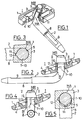
- the fixing device for automobile sun visors of the invention described as an exemplary embodiment comprises, as shown in Figure 1, the base body 1 and the support pin 2 which are mutually engageable. Both the base body 1 and the support pin 2 are made from plastics materials of appropriate strength and resilience.
- the base body 1 can have any shape appropriate for each particular application.
- the shape is, in general, determined basically by the internal finish of the vehicle passenger compartment.
- the base body 1 is essentially prismatic and on the inner side I thereof, which is the side facing the vehicle structure once the base body 1 is mounted thereon, is provided with the guide extension 3 forming an angle with the said inner side I , as shown in Figure 1.
- the anchorage of the base body 1 to the vehicle structure has not been shown in the drawing figures.
- the anchorage is achieved with screws mounted through the two through orifices 4 arranged in the respective longitudinal ends of the base body 1, as shown in Figures 1, 2 and 4.
- Figures 2 and 4 show how the guide extension 3 is basically frustoconical and has therethrough an axial orifice 5 which, as shown in Figures 2 and 3, is of circular section and is dimensioned so as to define a relatively thin side wall 6 in said guide extension 3.
- Figure 1 shows how the support pin 2 is essentially bent and is formed by the vertical arm 7 and the horizontal arm 8.
- the vertical arm 7 is the shorter one and, as shown in the drawings, is attached to the base body 1.
- a sun visor which, for the same reasons as given above, has not been shown in the figures, is attached to the horizontal arm 8.
- the horizontal arm 8 comprises a positioning flat 9 shown in Figure 1. Said flat is for more firmly setting the rest position or positions of the sun visor on the said horizontal arm 8.
- Figures 2 to 5 show how the vertical arm 7 of the support pin 2 has a cylindrical portion 10 which is dimensioned to mate with the axial orifice 5 of the guide extension 3 of the base body 1 and in which it is snugly lodged. Said cylindrical portion 10 and axial orifice 5 form the coupling means MA of the device of the invention.
- the free ends of the vertical arm 7 and of the guide extension 3 of the base body 1 have respective retaining means MR .
- Figures 1, 2 and 4 show how the cylindrical portion 10 of the vertical arm 7 of the support pin 2 is provided with the longitudinal gripping rib 11 which, in this embodiment, once the support pin 2 is engaged with the base body 1, extends to the opening B of the axial orifice 5 of the guide extension 3 of the base body 1.
- Figures 2 to 5 show how the axial orifice 5 of the guide extension 3 of the base body 1 is provided with the longitudinal positioning slot 12 which extends from the opening B of the axial orifice 5. Said positioning slot 12 extends coextensively with the gripping rib 11 formed on the cylindrical portion 10 housed in said axial orifice 5. Figures 2 and 3 show how the positioning slot 12 is dimensioned so that the gripping rib 11 may be snugly housed therein.
- the position occupied by the support pin 2 is the position in which the sun visor attached to the horizontal arm 8 of the support pin 2 is lying against the front side window of the vehicle.
- the gripping rib 11 of the vertical arm 7 of the support pin 2 is located in the positioning slot 12 of the guide extension 3 of the base body 1.
- the rotational torque required to be applied by the user to the sun visor to change the position thereof around the base body 1 must be greater than the resistant rotational torque resulting from the grip of the engagement of the cylindrical portion 10 with the axial orifice 5 and removal of the gripping rib 11 from its housing in the positioning slot 12.
- the position of the gripping rib 11 and of the positioning slot 12 relative to the support pin 2 and the base body 1, respectively, both shown in Figures 2 to 5, are the positions preferably adopted by the fixing device of the invention.
- the position occupied by the support pin 2 is the one in which the sun visor is disposed transversely to the running direction of the vehicle, i.e. lying against the vehicle windscreen.
- the gripping rib 11 causes resilient deformation of the guide extension 3 as shown in Figure 5.
- the gripping action on the cylindrical portion 10 is much greater than the gripping action that said guide extension 3 exerts on the cylindrical portion 10 when the gripping rib 11 is lodged in the positioning slot 12, because of the very resilient reaction of the constituent material of the guide extension 3, as shown in Figures 2 and 3.
- the rotational torque required to be applied by the user to the sun visor to change the position thereof around the base body 1 is, in any case, much greater relative to the rotational torque required by the known coupling embodiments between the support pin 2 and the base body 1.
Landscapes
- Engineering & Computer Science (AREA)
- Mechanical Engineering (AREA)
- Pivots And Pivotal Connections (AREA)
Applications Claiming Priority (3)
| Application Number | Priority Date | Filing Date | Title |
|---|---|---|---|
| ES9201316A ES2061358B1 (es) | 1992-06-24 | 1992-06-24 | Dispositivo de fijacion para viseras parasol de vehiculos automoviles. |
| ES9201316 | 1992-06-24 | ||
| PCT/ES1993/000050 WO1994000312A1 (es) | 1992-06-24 | 1993-06-16 | Dispositivo de fijacion para viseras parasol de vehiculos automoviles |
Publications (1)
| Publication Number | Publication Date |
|---|---|
| EP0598882A1 true EP0598882A1 (en) | 1994-06-01 |
Family
ID=8277444
Family Applications (1)
| Application Number | Title | Priority Date | Filing Date |
|---|---|---|---|
| EP93913029A Withdrawn EP0598882A1 (en) | 1992-06-24 | 1993-06-16 | Device for fixing sun visors of motor vehicles |
Country Status (4)
| Country | Link |
|---|---|
| EP (1) | EP0598882A1 (enExample) |
| AU (1) | AU4327693A (enExample) |
| ES (1) | ES2061358B1 (enExample) |
| WO (1) | WO1994000312A1 (enExample) |
Cited By (3)
| Publication number | Priority date | Publication date | Assignee | Title |
|---|---|---|---|---|
| RU2143346C1 (ru) * | 1998-12-15 | 1999-12-27 | ООО "Мобиль" | Устройство для наклона опорной оси противосолнечного козырька транспортного средства или стационарной установки |
| EP1008475A3 (de) * | 1998-12-12 | 2001-09-12 | Johnson Controls Interiors GmbH | Sonnenblende für Fahrzeuge |
| RU2282541C1 (ru) * | 2005-02-14 | 2006-08-27 | Общество с ограниченной ответственностью "Мобиль" | Держатель |
Families Citing this family (1)
| Publication number | Priority date | Publication date | Assignee | Title |
|---|---|---|---|---|
| US6994669B1 (en) | 1999-04-15 | 2006-02-07 | Heartport, Inc. | Apparatus and method for cardiac surgery |
Family Cites Families (6)
| Publication number | Priority date | Publication date | Assignee | Title |
|---|---|---|---|---|
| FR2431931A1 (fr) * | 1978-07-28 | 1980-02-22 | Maglum Sa | Support de pare-soleil |
| EP0009656A1 (de) * | 1978-10-06 | 1980-04-16 | Gebr. Happich GmbH | Schwenklager für Sonnenblenden von Fahrzeugen |
| FR2491403A1 (fr) * | 1980-10-06 | 1982-04-09 | Sacic | Dispositif d'articulation pour pare-soleil de vehicules |
| DE3134400A1 (de) * | 1981-08-31 | 1983-04-14 | Autopart Sweden GmbH, 8000 München | Sonnenblende fuer kraftfahrzeuge od.dgl. |
| GB2177057A (en) * | 1985-07-04 | 1987-01-14 | John Connor | Vehicle sun visor |
| ES2021198A6 (es) * | 1990-02-21 | 1991-10-16 | Ind Techno Matic Sa | Soporte para visera parasol. |
-
1992
- 1992-06-24 ES ES9201316A patent/ES2061358B1/es not_active Expired - Lifetime
-
1993
- 1993-06-16 WO PCT/ES1993/000050 patent/WO1994000312A1/es not_active Ceased
- 1993-06-16 AU AU43276/93A patent/AU4327693A/en not_active Abandoned
- 1993-06-16 EP EP93913029A patent/EP0598882A1/en not_active Withdrawn
Non-Patent Citations (1)
| Title |
|---|
| See references of WO9400312A1 * |
Cited By (3)
| Publication number | Priority date | Publication date | Assignee | Title |
|---|---|---|---|---|
| EP1008475A3 (de) * | 1998-12-12 | 2001-09-12 | Johnson Controls Interiors GmbH | Sonnenblende für Fahrzeuge |
| RU2143346C1 (ru) * | 1998-12-15 | 1999-12-27 | ООО "Мобиль" | Устройство для наклона опорной оси противосолнечного козырька транспортного средства или стационарной установки |
| RU2282541C1 (ru) * | 2005-02-14 | 2006-08-27 | Общество с ограниченной ответственностью "Мобиль" | Держатель |
Also Published As
| Publication number | Publication date |
|---|---|
| ES2061358R (enExample) | 1996-04-01 |
| ES2061358A2 (es) | 1994-12-01 |
| WO1994000312A1 (es) | 1994-01-06 |
| AU4327693A (en) | 1994-01-24 |
| ES2061358B1 (es) | 1996-11-16 |
Similar Documents
| Publication | Publication Date | Title |
|---|---|---|
| EP1007381B1 (en) | Snap-in mount | |
| US4973147A (en) | Holding device for a connector associated with an electrically controlled automotive mirror | |
| EP1445148B1 (en) | Accessory holder in cabin | |
| EP0169733A2 (en) | A rear view mirror assembly | |
| GB2294491A (en) | Roller blind winding apparatus | |
| EP0598882A1 (en) | Device for fixing sun visors of motor vehicles | |
| US3601352A (en) | Breakaway rearview mirror mounting assembly | |
| US3534938A (en) | Rear view mirrors | |
| EP0164114B1 (en) | Door window regulator | |
| US5333927A (en) | Sun shield for a windshield | |
| EP0575592A1 (en) | Spring-hinge of sun visors for motor vehicles | |
| GB1600425A (en) | Motor vehicle rear-view mirrors | |
| EP3984803B1 (en) | Dashboard with vehicle cockpit module assembly | |
| JPH08160874A (ja) | 画像表示モニターの取付装置 | |
| EP0515616A1 (en) | Semi-automatic opening and closing device for sun visor mirrors provided with a hinged cover | |
| JPH08276793A (ja) | 液晶テレビの車載取付装置 | |
| JP2009522507A (ja) | ワイヤークリップを使用したシャフトの軸方向固定装置 | |
| US11506864B2 (en) | Mirror device | |
| US4732461A (en) | External rearview mirror with releasable catch mechanism for motor vehicles | |
| JPS6231657B2 (enExample) | ||
| GB1595962A (en) | Motor vehicle rear-view mirrors | |
| EP4477473A1 (en) | Improved vehicular support system | |
| JP4211075B2 (ja) | 車両用サンバイザー等の支持軸の軸受装置及びこれを具備したサンバイザー等を支持するための支持装置 | |
| EP0598080B1 (en) | Spring-hinge for sun visors of motor vehicles | |
| JPH0635628Y2 (ja) | 電気接続箱の車体等への取付構造 |
Legal Events
| Date | Code | Title | Description |
|---|---|---|---|
| PUAI | Public reference made under article 153(3) epc to a published international application that has entered the european phase |
Free format text: ORIGINAL CODE: 0009012 |
|
| 17P | Request for examination filed |
Effective date: 19940315 |
|
| AK | Designated contracting states |
Kind code of ref document: A1 Designated state(s): DE ES FR GB IT |
|
| 17Q | First examination report despatched |
Effective date: 19950614 |
|
| STAA | Information on the status of an ep patent application or granted ep patent |
Free format text: STATUS: THE APPLICATION IS DEEMED TO BE WITHDRAWN |
|
| 18D | Application deemed to be withdrawn |
Effective date: 19960530 |