EP0598528A2 - Erkennungssystem mit magnetischer Kopplung - Google Patents
Erkennungssystem mit magnetischer Kopplung Download PDFInfo
- Publication number
- EP0598528A2 EP0598528A2 EP19930308857 EP93308857A EP0598528A2 EP 0598528 A2 EP0598528 A2 EP 0598528A2 EP 19930308857 EP19930308857 EP 19930308857 EP 93308857 A EP93308857 A EP 93308857A EP 0598528 A2 EP0598528 A2 EP 0598528A2
- Authority
- EP
- European Patent Office
- Prior art keywords
- coupling means
- portable
- portable passive
- coupling device
- passive member
- Prior art date
- Legal status (The legal status is an assumption and is not a legal conclusion. Google has not performed a legal analysis and makes no representation as to the accuracy of the status listed.)
- Withdrawn
Links
Images


Classifications
-
- G—PHYSICS
- G06—COMPUTING OR CALCULATING; COUNTING
- G06K—GRAPHICAL DATA READING; PRESENTATION OF DATA; RECORD CARRIERS; HANDLING RECORD CARRIERS
- G06K7/00—Methods or arrangements for sensing record carriers, e.g. for reading patterns
- G06K7/10—Methods or arrangements for sensing record carriers, e.g. for reading patterns by electromagnetic radiation, e.g. optical sensing; by corpuscular radiation
- G06K7/10009—Methods or arrangements for sensing record carriers, e.g. for reading patterns by electromagnetic radiation, e.g. optical sensing; by corpuscular radiation sensing by radiation using wavelengths larger than 0.1 mm, e.g. radio-waves or microwaves
- G06K7/10316—Methods or arrangements for sensing record carriers, e.g. for reading patterns by electromagnetic radiation, e.g. optical sensing; by corpuscular radiation sensing by radiation using wavelengths larger than 0.1 mm, e.g. radio-waves or microwaves using at least one antenna particularly designed for interrogating the wireless record carriers
- G06K7/10336—Methods or arrangements for sensing record carriers, e.g. for reading patterns by electromagnetic radiation, e.g. optical sensing; by corpuscular radiation sensing by radiation using wavelengths larger than 0.1 mm, e.g. radio-waves or microwaves using at least one antenna particularly designed for interrogating the wireless record carriers the antenna being of the near field type, inductive coil
Definitions
- the present invention relates to an identification system utilizing a portable passive tag which is powered by and communicates with a stationary reader. More particularly, the present invention relates to an improved identification system in which the portable tag is powered by and communicates with the stationary reader solely by means of magnetic coupling.
- Portable passive security tag systems are presently available that use magnetic coupling for energy transfer from a stationary power source to a credit card size portable uniquely coded security tag.
- An example of such a system is shown in Figure 1.
- transmit coil 10 of reader 12 creates a magnetic field (B) represented by flux lines 14.
- B magnetic field
- Flux lines 14 link with a coil 16 in portable tag 18 to induce current flow and thereby produce a voltage.
- Portable tag 18 rectifies that voltage to give a voltage high enough to power an application specific integrated circuit (ASIC).
- ASIC application specific integrated circuit
- the alternating voltage in coil 16 is also used to clock the ASIC.
- Tag 18 When a tag 18 and reader 12 are close enough for adequate transfer of energy, the tag ASIC 20 generates a coded signal that is sent back to reader 12. Tag 18 sends its code on a carrier frequency that is different than the reader 12 transmit frequency. Both magnetic coupling from tag 18 to reader 12 and electrostatic coupling from tag 18 to reader 12 have been tried.
- a problem frequently encountered by prior art portable passive security tag systems results from the necessity for both the reader and the tag to have transmit and receive antennas. Problems exist in decoupling the transmit and receive antennas sufficiently to achieve a desirable range. Specifically, the prior art security tag systems experience great difficulty in achieving adequate isolation between the transmit and receive coils in the magnetically coupled system.
- One proposed solution to overcome these difficulties is to utilize magnetic coupling from reader to tag and electrostatic coupling from tag to reader.
- United States Patent No. 4,818,855 shows an identification system in which a remotely powered portable member having circuitry for storing and transmitting coding information is provided.
- a first coupling device is provided for receiving a signal transmitted via one of a magnetic field and an electrostatic field.
- a power circuit connected to the first coupling device derives operating power from the received signal for use by the circuitry.
- a second coupling device is connected to the circuitry for transmitting coded information stored by the circuitry via the other one of the magnetic field and electrostatic field.
- the present identification system utilizes a magnetic field for energy transfer from the reader to the tag and a magnetic field for transmitting coded information from the tag to the reader.
- Mutual interference between transmit and receive magnetic field antennas for the same device is avoided by providing the receive antenna in an offset arrangement relative to the transmit antenna.
- the receive antenna is positioned with respect to the transmit antenna of the same device such that the net flux generated in the receive antenna by the signal of the transmit antenna is approximately zero. In such a manner, the effect of the transmit antenna on the companion receive antenna is nulled and any current generated in the receive coil is the result of the opposing device's transmit coil.
- Figure 1 is a schematic representation of a prior art identification system.
- Figure 2 is a schematic representation of a second prior art identification system illustrating the problems associated with mutual interference.
- Figure 3 is a schematic representation of a presently preferred embodiment of the present identification system.
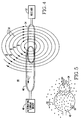
- Figure 4 is a schematic representation of the receiver unit of the identification system of Figure 3.
- Figure 5 is a schematic top view representation of the receiver unit of Figure 4.
- the identification system of the present invention solves the problem of mutual interference of magnetic coils by offsetting the receiver coil of a unit from that unit's transmission coil.
- Figure 2 illustrates the problem associated with mutual interference.
- stationary unit 22 is equipped with receiver 24 and alternating current driver 26.
- Power transmit coil 28 is connected to alternating current driver 26 and generates a magnetic field (B F1 ) whose flux lines are indicated at 30.
- Reader receiver coil 32 is connected to receiver 24 and is used to detect the presence of a portable tag.
- tag 34 On the opposing side of the identification system of Figure 2 is tag 34 having power receive coil 36 and transmit coil 38. Power receive coil 36 is connected to code transmitter means 40 which generates the signal (i F2 ) to be transmitted on transmit coil 38.
- the magnetic field (B F2 ) generated by transmit coil 38 is represented by flux lines 42.
- the frequency of the current (i F1 ) passing through transmit coil 28 (and, hence, the frequency of magnetic field 30) is different than the frequency of the current (i F2 ) passing through transmit coil 38 (and, hence, the frequency of magnetic field 42).
- the receive coils at each of the stationary unit and remote portable tag unit of the present invention are offset from their respective transmit coil.
- Figure 3 illustrates such an arrangement for both stationary unit 44 and tag 56.
- Figure 4 demonstrates the principles underlying the present invention in connection with stationary unit 44. It is to be understood that the same principles apply to tag unit 56.
- driver 46 is equipped with transmit coil 48 which generates a magnetic field (B) whose flux is represented by 50.
- the receiver 52 of stationary unit 44 is equipped with a receive coil 54 which is offset from the transmit coil 48 of the driver 46.
- Receive coil 54 is located with respect to transmit coil 48 such that the flux 50 generated by transmit coil 48 has no net effect on the generation of current in receiver coil 54.
- receiver coil 54 This is accomplished by locating receiver coil 54 at a position where half the flux lines 50 passing therethrough go in one direction and the remaining half go in the opposite direction. This can best be seen in Figure 5 wherein half of the flux lines (64) within receiver coil 54 are directed into the paper and half of the flux lines (66) passing through receiver coil 54 are directed out of the paper.
- the coils shown in Figures 3, 4 and 5 can be formed into shapes other than circles as deemed necessary by the particular application.
- the interference between the transmit antenna 48 and receive antenna 54 in the stationary unit 44 can be essentially eliminated by shifting the transmit coil 48 and receive coil 54 relative to each other.
- This same principle applies with regard to tag 56 in which the interference between transmit coil 60 and power receive coil 58 is essentially eliminated.
- Power receive coil 58 is arranged relative to transmit coil 60 such that the flux 62 generated by transmit coil 60 has no net effect on the generation of current in receive coil 58.
- transmit coil 48 is driven hard by driver 46 to produce flux lines 50 that link with receiver coil 54.
- the net flux linkages passing through receiver coil 54 can be made very close to zero. In this condition of zero flux linkages, the receive coil 54 and transmit coil 48 do not recognize the presence of each other.
- the advantages of total magnetic coupling for both reader and tag can be achieved. These advantages include increased range of operation, less interference from objects such as fluorescent lights, motor brushes and the like and less signal attenuation by conductive or magnetic or high dielectric objects passing between the reader and tag such as people, clothing, calculators and the like. Because communication is accomplished by a magnetic field, the effectiveness of this identification system is not significantly diminished by burying the tag in a shirt pocket, wallet, attache case or the like. Moreover, the present identification system allows for multiple tag recognition in a tight cluster of people.
- the present identification system was experimentally tested utilizing a reader having a ten inch diameter transmit coil and a ten inch diameter receive coil. These coils were shifted to achieve a null in the receiver coil voltage of greater than 75 dB. The actual null depth was not measured because at null the instrumentation used could not detect a signal.
- a ten inch diameter reader transmit coil and a five inch diameter reader receive coil were shifted to achieve a null.
- the transmit coil was driven hard enough to transfer sufficient energy to a two inch tag coil approximately three feet away to enable the tag to work.
- the unwanted voltage at the reader receive coil was less than about 150 mv peak-to-peak.
- the voltage on the transmit coil was about 1200 volts and the 150 mv signal was essentially the third or fifth harmonic of the transmit frequency of about 175 kHz.
- the null was not difficult to achieve. Shifting from the best position by about 1/16 inch increased the signal to about 300 mv peak-to-peak. A signal of 300 mv, or a much higher unwanted signal, does not challenge the dynamic range of a typical low noise receiver such as an operational amp supplied with +/- 15 volts. The residue unwanted pick-up can be filtered or processed out electronically. It was also found that the null was not significantly degraded by hand waving or passing a pocket calculator over and around the coil pair.
- the present identification system can be incorporated into systems requiring communication from a portable member to a stationary unit. By placing the portable tag on a commodity or mail bag, the location of the commodity can be tracked. In this same manner, the identification system can be used as a means of prisoner tracking.
- the portable unit can replace a key and be used for a parking lot entrance or as a keyless access to a house or car.
- the present invention can be used as a security device to restrict access to secure areas.
- the present invention can be used in connection with toll roads to record the entrance and exit of a vehicle from a restricted toll highway and deduct the toll from an account held by the owner of that tag.
- the isolation of a receive antenna from the effects of a transmit antenna on the same device has other applications in addition to the identification system discussed above.
- the present invention may also be used in transceivers to isolate the transmit and receive antennas of the same device.
- the present invention provides full duplex operation of the transceiver in an inexpensive manner.
Landscapes
- Engineering & Computer Science (AREA)
- Physics & Mathematics (AREA)
- Health & Medical Sciences (AREA)
- Toxicology (AREA)
- General Health & Medical Sciences (AREA)
- Electromagnetism (AREA)
- Computer Networks & Wireless Communication (AREA)
- Artificial Intelligence (AREA)
- Computer Vision & Pattern Recognition (AREA)
- General Physics & Mathematics (AREA)
- Theoretical Computer Science (AREA)
- Near-Field Transmission Systems (AREA)
- Burglar Alarm Systems (AREA)
- Radar Systems Or Details Thereof (AREA)
Applications Claiming Priority (2)
| Application Number | Priority Date | Filing Date | Title |
|---|---|---|---|
| US97677992A | 1992-11-16 | 1992-11-16 | |
| US976779 | 1992-11-16 |
Publications (1)
| Publication Number | Publication Date |
|---|---|
| EP0598528A2 true EP0598528A2 (de) | 1994-05-25 |
Family
ID=25524454
Family Applications (1)
| Application Number | Title | Priority Date | Filing Date |
|---|---|---|---|
| EP19930308857 Withdrawn EP0598528A2 (de) | 1992-11-16 | 1993-11-05 | Erkennungssystem mit magnetischer Kopplung |
Country Status (2)
| Country | Link |
|---|---|
| EP (1) | EP0598528A2 (de) |
| JP (1) | JPH0750621A (de) |
Cited By (3)
| Publication number | Priority date | Publication date | Assignee | Title |
|---|---|---|---|---|
| EP0810540A3 (de) * | 1996-05-30 | 1999-01-20 | Motorola, Inc. | Kontaktloses Identifikationssystem |
| WO2006041306A1 (en) * | 2004-10-13 | 2006-04-20 | Finn Staff | Electronic ID tag and co-operating antenna |
| FR2981486A1 (fr) * | 2011-10-12 | 2013-04-19 | Continental Automotive France | Dispositif et procede de communication sans contact a consommation electrique reduite |
Families Citing this family (1)
| Publication number | Priority date | Publication date | Assignee | Title |
|---|---|---|---|---|
| KR100434824B1 (ko) * | 2002-06-21 | 2004-06-07 | 전자부품연구원 | 이중대역 무선 인식장치 |
-
1993
- 1993-11-05 EP EP19930308857 patent/EP0598528A2/de not_active Withdrawn
- 1993-11-10 JP JP5305807A patent/JPH0750621A/ja not_active Withdrawn
Cited By (6)
| Publication number | Priority date | Publication date | Assignee | Title |
|---|---|---|---|---|
| EP0810540A3 (de) * | 1996-05-30 | 1999-01-20 | Motorola, Inc. | Kontaktloses Identifikationssystem |
| WO2006041306A1 (en) * | 2004-10-13 | 2006-04-20 | Finn Staff | Electronic ID tag and co-operating antenna |
| GB2441185A (en) * | 2004-10-13 | 2008-02-27 | Trac Id Systems As | Electronic ID tag and co-operating antenna |
| GB2441185B (en) * | 2004-10-13 | 2009-04-01 | Trac Id Systems As | Electronic ID tag and co-operating antenna |
| US7688210B2 (en) | 2004-10-13 | 2010-03-30 | Trac Id Systems As | Electronic ID tag and co-operating antenna |
| FR2981486A1 (fr) * | 2011-10-12 | 2013-04-19 | Continental Automotive France | Dispositif et procede de communication sans contact a consommation electrique reduite |
Also Published As
| Publication number | Publication date |
|---|---|
| JPH0750621A (ja) | 1995-02-21 |
Similar Documents
| Publication | Publication Date | Title |
|---|---|---|
| EP0434817B1 (de) | Näherungsdetektionsgerät | |
| US8305193B2 (en) | RFID protection device, and related methods | |
| US4782342A (en) | Proximity identification system with lateral flux paths | |
| EP0766200A3 (de) | Antenne für Leser/Schreiber | |
| EP0429617B1 (de) | System zur übertragung und feststellung von elektromagnetischer energie | |
| EP0886232B1 (de) | Schreib-/Lesevorrichtung, Stromversorgungssystem und Kommunikationssystem | |
| US5426667A (en) | System for the contactless exchange of data, and responder for use in such a system | |
| US5382952A (en) | Transponder for proximity identification system | |
| US6950008B2 (en) | Authentication of a first transceiver unit with respect to a second transceiver unit located at a distance | |
| JPH08296354A (ja) | 送受信機用改善インダクタ/アンテナ | |
| US8237549B2 (en) | RFID protection system, device, combination, and related methods | |
| US4600829A (en) | Electronic proximity identification and recognition system with isolated two-way coupling | |
| US6176433B1 (en) | Reader/writer having coil arrangements to restrain electromagnetic field intensity at a distance | |
| US7014103B2 (en) | Differential radio frequency identification reader | |
| EP1544784A4 (de) | Antenneneinrichtung und kommunikationseinrichtung mit der antenneneinrichtung | |
| US9965714B1 (en) | RFID disruption device and related methods | |
| EP0878891A2 (de) | Leistungsübertragungssystem, Leistungsübertragungs- Kommunikationssystem sowie Leser und/oder Schreiber | |
| EP0598528A2 (de) | Erkennungssystem mit magnetischer Kopplung | |
| Roz et al. | Using low power transponders and tags for RFID applications | |
| US4888474A (en) | Proximity identification system with lateral flux magnetic rod coupling | |
| JP3014142B2 (ja) | 誘導性結合された情報検索システム | |
| JPH11345294A (ja) | リーダまたは/およびライタシステムおよびこれを用いた通信システム |
Legal Events
| Date | Code | Title | Description |
|---|---|---|---|
| PUAI | Public reference made under article 153(3) epc to a published international application that has entered the european phase |
Free format text: ORIGINAL CODE: 0009012 |
|
| AK | Designated contracting states |
Kind code of ref document: A2 Designated state(s): DE FR GB NL |
|
| 18W | Application withdrawn |
Withdrawal date: 19951205 |