EP0598285B1 - Reciprocating-knife cutting machine - Google Patents
Reciprocating-knife cutting machine Download PDFInfo
- Publication number
- EP0598285B1 EP0598285B1 EP93117861A EP93117861A EP0598285B1 EP 0598285 B1 EP0598285 B1 EP 0598285B1 EP 93117861 A EP93117861 A EP 93117861A EP 93117861 A EP93117861 A EP 93117861A EP 0598285 B1 EP0598285 B1 EP 0598285B1
- Authority
- EP
- European Patent Office
- Prior art keywords
- knife
- cutting machine
- cutting
- protective
- machine according
- Prior art date
- Legal status (The legal status is an assumption and is not a legal conclusion. Google has not performed a legal analysis and makes no representation as to the accuracy of the status listed.)
- Expired - Lifetime
Links
Images
Classifications
-
- B—PERFORMING OPERATIONS; TRANSPORTING
- B26—HAND CUTTING TOOLS; CUTTING; SEVERING
- B26D—CUTTING; DETAILS COMMON TO MACHINES FOR PERFORATING, PUNCHING, CUTTING-OUT, STAMPING-OUT OR SEVERING
- B26D7/00—Details of apparatus for cutting, cutting-out, stamping-out, punching, perforating, or severing by means other than cutting
- B26D7/22—Safety devices specially adapted for cutting machines
-
- B—PERFORMING OPERATIONS; TRANSPORTING
- B26—HAND CUTTING TOOLS; CUTTING; SEVERING
- B26D—CUTTING; DETAILS COMMON TO MACHINES FOR PERFORATING, PUNCHING, CUTTING-OUT, STAMPING-OUT OR SEVERING
- B26D7/00—Details of apparatus for cutting, cutting-out, stamping-out, punching, perforating, or severing by means other than cutting
- B26D7/08—Means for treating work or cutting member to facilitate cutting
- B26D7/12—Means for treating work or cutting member to facilitate cutting by sharpening the cutting member
-
- B—PERFORMING OPERATIONS; TRANSPORTING
- B26—HAND CUTTING TOOLS; CUTTING; SEVERING
- B26F—PERFORATING; PUNCHING; CUTTING-OUT; STAMPING-OUT; SEVERING BY MEANS OTHER THAN CUTTING
- B26F1/00—Perforating; Punching; Cutting-out; Stamping-out; Apparatus therefor
- B26F1/38—Cutting-out; Stamping-out
- B26F1/3806—Cutting-out; Stamping-out wherein relative movements of tool head and work during cutting have a component tangential to the work surface
- B26F1/3813—Cutting-out; Stamping-out wherein relative movements of tool head and work during cutting have a component tangential to the work surface wherein the tool head is moved in a plane parallel to the work in a coordinate system fixed with respect to the work
- B26F1/382—Cutting-out; Stamping-out wherein relative movements of tool head and work during cutting have a component tangential to the work surface wherein the tool head is moved in a plane parallel to the work in a coordinate system fixed with respect to the work wherein the cutting member reciprocates in, or substantially in, a direction parallel to the cutting edge
Definitions
- the invention relates to a butt knife cutting machine according to the preamble of claim 1.
- DE 26 19 789 B2 which forms the preamble of claim 1, has disclosed a butt knife cutting device for processing flat material, ie for cutting several layers of fabric placed on a table-top-like base, which has a knife protection device for covering the butt knife cutting edge.
- a knife protection device for covering the butt knife cutting edge.
- this knife guard can be, for example, in the form of a U-shaped view from above Plastic glass hood exist, which surrounds the knife in a U-shape.
- Such plexiglass covers have the disadvantage that they obstruct the view of the cutting point due to the constant dust and a parallax shift.
- a dusty plexiglass cover which is inevitably necessary, there is also a risk of injury by reaching between the knife and the inside of the cover.
- retracting the machine after the cut is no longer possible due to the falling covering, ie the machine must be lifted over the fabric layer or moved around the cutting table.
- Such a plexiglass cover also has the disadvantage that the manual holding of the fabric layer by the user in the immediate vicinity of the cutting is no longer possible, since this space is covered by the plexiglass cover. This results in cut inaccuracies which should be avoided by lifting up the protective device, but protection is no longer guaranteed.
- the known device proposes a band-shaped protective device which runs to the side of the knife-edge, which is connected in its lower region to the hold-down device of the knife protective device which can be moved up and down and whose flexible band is added in the upper region whose upward movement is rolling up, for example.
- the impact knife is made visible.
- Such a knife guard is arranged below the grinding device so that there is no mutual hindrance in the up and down movement of both the grinding device and the hold-down device.
- a disadvantage of this device is the complex mechanism for guiding the side masking tapes.
- the known device proposes to arrange a telescopic rod as knife protection instead of the band-shaped measuring protection device in front of or next to the knife edge.
- a rigid rod can also be used as knife protection, which penetrates the grinding device provided.
- arranging such a single bar in front of or next to the butt knife cutting edge cannot provide effective protection against finger contact with the cutting edge.
- the free visibility of the knife edge is impaired by a protective rod arranged in front of it.
- the cutting machine according to the invention is therefore based on the object of providing a simple and effective protective device against contact of the butt knife cutting edge, on the one hand there being no visual obstruction during the cutting process and on the other hand the grinding device for sharpening the butt knife cutting edge remains fully effective.
- the butt knife cutting device has the advantage over the known devices that there are no obstructions in the form of plexiglass panes or band knife covers. Rather, effective protection against contact of the butt knife cutting edge is achieved in that, in particular, two protective rods are arranged at a short distance in front of the butt knife cutting edge, which surround the cutting edge of the butt knife so closely that contact with the cutting edge is prevented.
- the lower part of the protective rods is connected to the hold-down device or the presser foot, which is pushed upwards depending on the height of the fabric layer. When the hold-down device is pushed up, the protective rods also move upwards and are guided on the machine housing and in particular in the connecting rod housing.
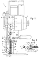
- the basic structure of the butt knife cutting machine 1 shown in FIG. 1 corresponds to that of a machine such as that shown and described in DE 26 19 789 B2.
- a machine has a machine housing 2 with an electric drive for an upward and downward moving thrust knife 3.
- a flywheel 5 with an eccentric bolt 6 is provided on the motor shaft 4, on which a connecting rod 7 with a bearing 8 is mounted.
- the lower end of the connecting rod 7 is connected to the butt knife end 9 via a bearing 10.
- the above known drive is shown only schematically in the drawing.
- the butt knife cutting machine 1 has in its lower region a base plate 11 which is connected to the machine housing 2 via a U-shaped support bracket 12.
- a bow-shaped hold-down 13 is attached to a vertical rod 14 which is guided up and down on the machine housing 2.
- the machine housing contains a braking device, not shown, for the rod 14, which can be released by operating an operating lever, so that the hold-down 13 falls down under its own weight.
- FIG. 1 also shows a knife grinding device 15, which consists of two V-shaped grinding belts 16, 17 aligned with one another.
- the deflection rollers for the belts of the knife grinding device are driven by the rotary knife drive, the grinding device is lowered along the butt knife and raised again to sharpen its cutting edge 18.
- the knife sharpening device is guided via a guide rod 19.
- a knife protection device 20 in front of the butt knife 3, which consists of two protective bars 21, 22 arranged directly in front of the cutting edge 18.
- These protective rods 21, 22 are each inserted into a sleeve 23 in their lower region and clamped by means of a screw 24.
- the sleeve 23 is fastened on the hold-down device 13.
- the protective rods 21, 22 therefore perform the upward and downward movement of the hold-down device 13 with the vertical rod 14.
- the respective protective rod 21, 22 is guided in a guide sleeve 25 on the machine housing 2 and protrudes along the dashed line 26 shown in FIG. 1 into the connecting rod housing 27 of the cutting machine, in particular in the uppermost position.
- the two protective rods 21, 22 penetrate the two grinding belt arms 16, 17 in a respective bore 28, so that both the knife grinding device 15 and the hold-down device 13, 14 with protective rods 21, 22 can be moved up and down independently of one another. If the protective rods 21, 22 protruding into the connecting rod housing 27 during its upward movement come too closely to the thrust knife drive and in particular to the connecting rod 7, an increase in the distance can be achieved by means of spacer sleeves between connecting rod housing 27 (housing cover) and machine housing 2 with an additional sealing ring. These measures can also be used to equip older machines with appropriate protective bars.
- the connecting plane 30 of the two protective bars 21, 22 is at a distance s 1 in front of the “tip” 18 ′ of the cutting edge 18 of the butt knife 3.
- This distance s 1 is advantageously s 1 8 8 mm, so that touching the front cutting edge 18 'is no longer possible.
- "s 1 " can also be the direct distance of the respective rod 21, 22 from the knife tip 18 ', the "tip"18' in FIG. 2 being the "front cutting edge".
- the lateral distance s 2 of the two protective bars 21, 22 is also kept very small and is also s 2 8 8 mm. This ensures that the front cutting tip 18 'of the cutting edge 18 cannot be touched manually due to the two protective bars 21, 22.
- a regulation of the German professional association states that adequate protection against sharp edges against contact is guaranteed with a gap width of ⁇ 8 mm, ie the gap width s 1 , s 2 formed by the protective rods must be significantly smaller than the finger width.
- the invention is not restricted to the exemplary embodiment shown and described. Rather, it also encompasses all professional developments and improvements within the framework of the inventive idea.
Landscapes
- Life Sciences & Earth Sciences (AREA)
- Forests & Forestry (AREA)
- Engineering & Computer Science (AREA)
- Mechanical Engineering (AREA)
- Treatment Of Fiber Materials (AREA)
- Harvester Elements (AREA)
- Processing Of Stones Or Stones Resemblance Materials (AREA)
- Finish Polishing, Edge Sharpening, And Grinding By Specific Grinding Devices (AREA)
- Nonmetal Cutting Devices (AREA)
Abstract
Description
Die Erfindung betrifft eine Stoßmesser-Zuschneidemaschine nach dem Oberbegriff des Anspruchs 1.The invention relates to a butt knife cutting machine according to the preamble of
Aus der den Oberbegriff des Anspruchs 1 bildenden DE 26 19 789 B2 ist eine Stoßmesser-Schneidvorrichtung zur Bearbeitung von Flachmaterial, d. h. zum Schneiden mehrerer, auf einer tischplattenartigen Unterlage aufgelegter Stofflagen bekanntgeworden, die eine Messerschutzeinrichtung zur Abdeckung der Stoßmesser-Schneidkante aufweist. Wie in dieser Druckschrift beschrieben, war es bei älteren Stoßmesser-Zuschneidemaschinen üblich, daß die Schneidkante des Stoßmessers ungeschützt geführt wurde, was zu schweren Arbeitsunfällen führen konnte. Demzufolge wurden einige Stoßmesserschutzeinrichtungen vorgeschlagen, die eine Berührung des Stoßmessers vermeiden sollten. Wie in der oben genannten Druckschrift angegeben, kann dieser Messerschutz beispielsweise in Form einer in der Draufsicht U-förmigen Plastikglashaube bestehen, die das Stoßmesser U-förmig umgibt. Derartige Plexiglasverdeckungen haben den Nachteil, daß sie die Sicht auf die Schneidstelle aufgrund der ständigen Verstaubung und einer Parallaxenverschiebung behindern. Bei der zwangsläufig notwendigen Reinigung eines verstaubten Plexiglasschutzes besteht ebenfalls eine Verletzungsgefahr durch das Hineingreifen zwischen Messer und Innenseite der Verdeckung. Weiterhin ist das Zurückziehen der Maschine nach dem Trennschnitt durch die herabfallende Verdeckung nicht mehr ohne weiteres möglich, d. h. die Maschine muß über die Stofflage hinweg gehoben oder um den Zuschneidetisch herumgefahren werden. Eine solche Plexiglasverdeckung hat weiterhin den Nachteil, daß das manuelle Halten der Stofflage durch die Benutzerperson in unmittelbarer Schneidnähe nicht mehr möglich ist, da dieser Raum durch die Plexiglasabdeckung verdeckt ist. Hierdurch ergeben sich Schnittungenauigkeiten, die durch ein Hochnehmen der Schutzeinrichtung vermieden werden sollen, wodurch jedoch der Schutz nicht mehr gewährleistet ist. Da ein solcher Plastikschutz an der Niederhaltervorrichtung bzw. am Stoffdrücker befestigt ist, wird dieser noch schwerer und bewirkt durch das Verschieben der Stofflagen ungenaue Zuschnitte. Schließlich stellt die großräumige Plexiglasverdeckung einen zusätzlichen Ballast dar, der die Maschine noch kopflastiger macht und den Zugriff zur Gefahrenstelle dennoch nicht wirksam verhindert. Solche Plexiglasverdeckungen weisen demnach insgesamt eine Reihe von Nachteilen auf.DE 26 19 789 B2, which forms the preamble of
Wie aus der oben genannten Druckschrift weiterhin entnehmbar ist, steht der Anordnung eines Messerschutzes unmittelbar vor oder neben der Stoßmesserschneidkante die Forderung entgegen, daß die Stoßmesser-Schneidkante gut einsehbar sein muß. Weiterhin weisen derartige handgeführte Stoßmessermaschinen unter dem Maschinengehäuse eine Schleifvorrichtung für die Stoßmesser-Schneidkante auf, die zum Schleifen aus einer oberen Ruhelage heraus längs des Stoßmessers nach unten abgesenkt und dann wieder angehoben wird. Eine Schutzeinrichtung unmittelbar vor der Stoßmesser-Schneidkante würde einer solchen Schleifvorrichtung im Wege stehen.As can also be seen from the above-mentioned document, the arrangement of a knife guard directly in front of or next to the butt knife cutting edge is countered by the requirement that the butt knife cutting edge must be clearly visible. Furthermore, such hand-held butt knife machines have, under the machine housing, a grinding device for the butt knife cutting edge, which is used for grinding from a upper rest position is lowered along the butt knife and then raised again. A protective device immediately in front of the knife edge would stand in the way of such a grinding device.
Die bekannte Einrichtung gemäß der oben genannten Druckschrift schlägt zur Lösung dieses Problems eine seitlich der Stoßmesser-Schneidkanten verlaufende, bandförmige Schutzeinrichtung vor, die in ihrem unteren Bereich mit dem auf- und abbewegbaren Niederhalter der Messerschutzeinrichtung verbunden ist und dessen flexibles Band sich im oberen Bereich bei dessen Aufwärtsbewegung beispielsweise aufrollt. Im untersten Bereich der Messerschutzeinrichtung ist das Stoßmesser sichtbar ausgebildet. Ein derartiger Stoßmesserschutz wird unterhalb der Schleifvorrichtung angeordnet, so daß eine gegenseitige Behinderung bei der Auf- und Abwärtsbewegung sowohl der Schleifvorrichtung als auch des Niederhalters nicht stattfindet. Nachteilig an dieser Einrichtung ist jedoch die aufwendige Mechanik für die Führung der seitlichen Abdeckbänder.To solve this problem, the known device according to the above-mentioned publication proposes a band-shaped protective device which runs to the side of the knife-edge, which is connected in its lower region to the hold-down device of the knife protective device which can be moved up and down and whose flexible band is added in the upper region whose upward movement is rolling up, for example. In the lowest area of the knife protection device, the impact knife is made visible. Such a knife guard is arranged below the grinding device so that there is no mutual hindrance in the up and down movement of both the grinding device and the hold-down device. A disadvantage of this device, however, is the complex mechanism for guiding the side masking tapes.
Alternativ schlägt die bekannte Einrichtung vor, anstelle der bandförmigen Meßschutzeinrichtung vor oder neben der Stoßmesser-Schneidkante einen teleskopierbaren Stab als Messerschutz anzuordnen. Anstelle eines teleskopierbaren Stabes kann auch ein starrer Stab als Messerschutz verwendet werden, der die vorgesehene Schleifvorrichtung durchsetzt. Die Anordnung eines solchen einzelnen Stabes vor oder neben der Stoßmesser-Schneidkante kann jedoch einen wirksamen Schutz gegen eine Fingerberührung der Schneidkante nicht bieten. Insbesondere ist auch die freie Sichtbarkeit der Stoßmesserschneide durch einen davor angeordneten Schutzstab beeinträchtigt.Alternatively, the known device proposes to arrange a telescopic rod as knife protection instead of the band-shaped measuring protection device in front of or next to the knife edge. Instead of a telescopic rod, a rigid rod can also be used as knife protection, which penetrates the grinding device provided. However, arranging such a single bar in front of or next to the butt knife cutting edge cannot provide effective protection against finger contact with the cutting edge. In particular, the free visibility of the knife edge is impaired by a protective rod arranged in front of it.
Aus der CH-A-297 819 ist eine weitere Stoßmesser-Zuschneidemaschine für Flachmaterial bekannt geworden, bei welcher der Stoffniederhalter mit einem Schutzbügel versehen ist, der die Stoßmesser-Schneidkante abschirmt.From CH-A-297 819 a further butt knife cutting machine for flat material has become known, in which the fabric hold-down device is provided with a protective bracket which shields the butt knife cutting edge.
Der erfindungsgemäßen Zuschneidemaschine liegt demzufolge die Aufgabe zugrunde, eine einfache und wirksame Schutzeinrichtung gegen eine Berührung der Stoßmesser-Schneidkante zu schaffen, wobei zum einen keine Sichtbehinderung beim Schneidvorgang vorliegt und zum anderen auch die Schleifvorrichtung zum Schärfen der Stoßmesser-Schneidkante vollwirksam bleibt.The cutting machine according to the invention is therefore based on the object of providing a simple and effective protective device against contact of the butt knife cutting edge, on the one hand there being no visual obstruction during the cutting process and on the other hand the grinding device for sharpening the butt knife cutting edge remains fully effective.
Diese Aufgabe wird ausgehend von einer Stoßmesser-Zuschneidemaschine nach dem Oberbegriff des Anspruchs 1 durch die kennzeichnenden Merkmale des Anspruchs 1 gelöst.This object is achieved on the basis of a butt knife cutting machine according to the preamble of
In den Unteransprüchen sind vorteilhafte und zweckmäßige Weiterbildungen der Stoßmesser-Zuschneidemaschine gemäß Anspruch 1 angegeben.Advantageous and expedient further developments of the butt knife cutting machine according to
Die erfindungsgemäße Stoßmesser-Schneidvorrichtung hat gegenüber den bekannten Einrichtungen den Vorteil, daß keinerlei Sichtbehinderungen in Form von Plexiglasscheiben oder Bandmesserabdeckungen vorhanden sind. Vielmehr wird ein wirksamer Schutz gegen Berührung der Stoßmesser-Schneidkante dadurch erzielt, daß in einem geringen Abstand vor der Stoßmesser-Schneidkante insbesondere zwei Schutzstäbe angeordnet sind, die derart eng die Schneidkante des Stoßmessers umgeben, daß eine Berührung der Schneidkante verhindert wird. Dabei sind die Schutzstäbe in ihrem unteren Bereich mit der Niederhaltervorrichtung bzw. dem Stoffdrückerfuß verbunden, der je nach Stofflagenhöhe nach oben geschoben wird. Beim Hochschieben der Niederhaltervorrichtung verschieben sich die Schutzstäbe ebenfalls nach oben und sind hierbei am Maschinengehäuse und insbesondere im Pleuelgehäuse geführt.The butt knife cutting device according to the invention has the advantage over the known devices that there are no obstructions in the form of plexiglass panes or band knife covers. Rather, effective protection against contact of the butt knife cutting edge is achieved in that, in particular, two protective rods are arranged at a short distance in front of the butt knife cutting edge, which surround the cutting edge of the butt knife so closely that contact with the cutting edge is prevented. The lower part of the protective rods is connected to the hold-down device or the presser foot, which is pushed upwards depending on the height of the fabric layer. When the hold-down device is pushed up, the protective rods also move upwards and are guided on the machine housing and in particular in the connecting rod housing.
Durch den sehr einfachen Aufbau einer solchen Messerschutzeinrichtung können komplizierte Teile eingespart werden. Die Schutzstäbe bewegen sich mit der geführten Niederhaltervorrichtung und decken die Schneidkante des Stoßmessers wirksam ab.The very simple construction of such a knife guard means that complicated parts can be saved. The protective rods move with the guided hold-down device and effectively cover the cutting edge of the straight knife.
Weitere Einzelheiten der Erfindung sind in der Zeichnung dargestellt. In der nachfolgenden Beschreibung eines Ausführungsbeispiels sind weitere Einzelheiten und Vorteile der Erfindung angegeben.
- Die Fig. 1
- zeigt eine Seitenansicht einer erfindungsgemäßen Stoßmesser-Zuschneidemaschine,
- die Fig. 2
- eine Draufsicht entlang der Schnittfläche A-B in Fig. 1.
- 1
- shows a side view of a butt knife cutting machine according to the invention,
- 2
- 2 shows a plan view along the sectional area AB in FIG. 1.
Die in der Fig. 1 dargestellte Stoßmesser-Zuschneidemaschine 1 entspricht in ihrem grundsätzlichen Aufbau einer Maschine, wie sie beispielsweise in der DE 26 19 789 B2 gezeigt und beschrieben ist. Eine solche Maschine besitzt ein Maschinengehäuse 2 mit einem elektrischen Antrieb für ein sich auf- und abwärtsbewegendes Stoßmesser 3. Hierfür ist auf der Motorwelle 4 eine Schwungscheibe 5 mit einem Exzenterbolzen 6 vorgesehen, an welchem ein Pleuel 7 mit Lager 8 gelagert ist. Das untere Ende des Pleuels 7 ist mit dem Stoßmesserende 9 über ein Lager 10 verbunden. Der vorstehende bekannte Antrieb ist in der Zeichnung nur schematisch dargestellt.The basic structure of the butt
Die Stoßmesser-Zuschneidemaschine 1 weist in ihrem unteren Bereich eine Fußplatte 11 auf, die über eine U-förmige Tragstütze 12 mit dem Maschinengehäuse 2 verbunden ist. Ein bügelförmiger Niederhalter 13 ist an einer vertikalen Stange 14 befestigt, die am Maschinengehäuse 2 auf- und abbewegbar geführt ist. Dabei enthält das Maschinengehäuse eine nicht näher dargestellte Bremseinrichtung für die Stange 14, die durch Betätigung eines Bedienungshebels gelöst werden kann, so daß der Niederhalter 13 unter seinem Eigengewicht nach unten fällt.The butt
Eine solche Sicherheitseinrichtung ist in der nicht vorveröffentlichten älteren Anmeldung der Anmelderin P 42 08 375.3 beispielhaft beschrieben. Auf den Inhalt dieser Patentanmeldung wird ausdrücklich verwiesen.Such a safety device is described by way of example in the not previously published older application by the applicant P 42 08 375.3. We expressly refer to the content of this patent application.
In der Fig. 1 ist weiterhin eine Messerschleifvorrichtung 15 gezeigt, die aus zwei V-förmig zueinander ausgerichteten Schleifbändern 16, 17 besteht. Die Umlenkrollen für die Bänder der Messerschleifvorrichtung werden durch den Stoßmesserantrieb angetrieben, wobei die Schleifvorrichtung längs des Stoßmessers abgesenkt und wieder angehoben wird, um dessen Schneidkante 18 zu schärfen. Die Führung der Messerschleifvorrichtung geschieht über eine Führungsstange 19.1 also shows a
Zur Absicherung der vorderen Schneidkante 18 mit Schneidspitze 18' des Stoßmessers 3 befindet sich vor dem Stoßmesser 3 eine Messerschutzeinrichtung 20, die aus zwei unmittelbar vor der Schneidkante 18 angeordneten Schutzstäben 21, 22 besteht. Diese Schutzstäbe 21, 22 sind in ihrem unteren Bereich in jeweils eine Hülse 23 eingesteckt und mittels einer Schraube 24 verklemmt. Die Hülse 23 ist auf dem Niederhalter 13 befestigt. Die Schutzstäbe 21, 22 führen daher die Auf- und Abwärtsbewegung des Niederhalters 13 mit der vertikalen Stange 14 durch.To secure the
In seinem oberen Bereich ist der jeweilige Schutzstab 21, 22 in einer Führungshülse 25 am Maschinengehäuse 2 geführt und ragt entlang der in Fig. 1 dargestellten gestrichelten Linie 26 in das Pleuelgehäuse 27 der Zuschneidemaschine insbesondere in der obersten Stellung hinein. Dabei durchdringen die beiden Schutzstäbe 21, 22 die beiden Schleifbänderarme 16, 17 in einer jeweiligen Bohrung 28, so daß sowohl die Messerschleifvorrichtung 15 als auch die Niederhaltervorrichtung 13, 14 mit Schutzstangen 21, 22 unabhängig voneinander auf- und abbewegt werden können. Sofern die in das Pleuelgehäuse 27 bei dessen Aufwärtsbewegung hineinragenden Schutzstäbe 21, 22 zu eng an den Stoßmesserantrieb und insbesondere an die Pleuelstange 7 heranreichen, kann eine Abstandsvergrößerung durch eventuelle Abstandshülsen zwischen Pleuelgehäuse 27 (Gehäusedeckel) und Maschinengehäuse 2 mit einem zusätzlichen Dichtungsring bewerkstelligt werden. Durch diese Maßnahmen können auch ältere Maschinen mit entsprechenden Schutzstäben ausgestattet werden.In its upper area, the respective
Wie aus Fig. 2 ersichtlich, befindet sich die Verbindungsebene 30 der beiden Schutzstäbe 21, 22 in einem Abstand s1 vor der "Spitze" 18' der Schneidkante 18 des Stoßmessers 3. Dieser Abstand s1 beträgt vorteilhafterweise s1 ≤ 8 mm, so daß eine Berührung der vorderen Schneide 18' nicht mehr möglich ist. Selbstverständlich kann "s1" auch der direkte Abstand des jeweiligen Stabes 21, 22 zur Messerspitze 18' sein, wobei die "Spitze" 18' in Fig. 2 die "vordere Schneidkante" ist.As can be seen from FIG. 2, the connecting
Auch der seitliche Abstand s2 der beiden Schutzstäbe 21, 22 ist sehr klein gehalten und beträgt ebenfalls s2 ≤ 8 mm. Hierdurch ist sichergestellt, daß die vordere Schneidspitze 18' der Schneidkante 18 aufgrund der beiden Schutzstäbe 21, 22 nicht manuell berührt werden kann. Hierzu gibt eine Vorschrift der deutschen Berufsgenossenschaft an, daß ein ausreichender Schutz vor scharfen Kanten gegen Berühren bei einer Spaltbreite von ≤ 8 mm gewährleistet ist, d. h. die durch die Schutzstäbe gebildete Spaltbreite s1, s2 muß deutlich kleiner als die Fingerbreite sein.The lateral distance s 2 of the two
Aus Fig. 2 ist die U-förmige Ausbildung der Tragstütze 12 ersichtlich, in welcher das Stoßmesser 3 geführt ist, so daß nur der vordere Bereich 29 mit der Schneidkante 18 aus der U-förmigen Tragstütze 12 herausragt.From Fig. 2 the U-shaped design of the
Die Erfindung ist nicht auf das dargestellte und beschriebene Ausführungsbeispiel beschränkt. Sie umfaßt auch vielmehr alle fachmännischen Weiterbildungen und Verbesserungen im Rahmen des erfindungsgemäßen Gedankens.The invention is not restricted to the exemplary embodiment shown and described. Rather, it also encompasses all professional developments and improvements within the framework of the inventive idea.
Claims (8)
- Reciprocating-knife cutting machine for cutting several layers of fabric or the like laid on a table plate-like support, with a reciprocating knife (3) extending downwards from a machine housing, whereof the cutting edge (18) is covered by means of a knife protection device (20), which is connected to a holding-down device (13, 14) able to move up and down, the knife protection device (20) comprising a protective bar (21, 22) located in the region in front of the cutting edge (18), which bar (21, 22) is connected at its lower ends to the holding-down device (13, 14), characterised in that the knife protection device (20) is formed from at least two protective bars (21, 22) arranged one beside the other and located at a short distance in front of the cutting edge (18), which bars are connected at their lower ends to the holding-down device (13, 14) and that the protective bars (21, 22) are arranged around the front cutting edge (18') of the reciprocating knife (3) so that a gap of ≤ 8 mm results.
- Cutting machine according to Claim 1, characterised in that the distance from the connecting plane (30) through the two protective bars (21, 22) to the cutting edge (18') has an amount of s1 ≤ 8 mm.
- Cutting machine according to Claim 1, characterised in that the distance between the two protective bars (21, 22) amounts to s2 ≤ 8 mm.
- Cutting machine according to Claim 1, characterised in that the protective bars (21, 22) are guided longitudinally in the connecting rod housing (27).
- Cutting machine according to one of the preceding Claims, characterised in that provided below the machine housing (2) is a knife grinding device (15) consisting of two revolving grinding belts arranged in a V-shape with respect to each other, the protective bars (21, 22) preferably passing through the grinding belt arms (28) of the knife grinding device.
- Cutting machine according to one of the preceding Claims, characterised in that as they move upwards with their holding-down device (13, 14), the protective bars (21, 22) penetrate the connecting rod housing (27).
- Cutting machine according to Claim 5, characterised in that the protective bars (21, 22) in the connecting rod housing (27) are guided in front of the revolving connecting rod (7), if necessary spacer sleeves and/or seals being provided between the machine housing (2) and connecting rod covering housing (27).
- Cutting machine according to one of the preceding Claims, characterised in that the holding-down device (13) is constructed as a fabric presser foot and on its upper surface comprises fastening sleeves (23) with fastening screws (24), in which the lower ends of the protective bars (21, 22) are fixed.
Applications Claiming Priority (2)
| Application Number | Priority Date | Filing Date | Title |
|---|---|---|---|
| DE4237351 | 1992-11-05 | ||
| DE4237351A DE4237351A1 (en) | 1992-11-05 | 1992-11-05 |
Publications (2)
| Publication Number | Publication Date |
|---|---|
| EP0598285A1 EP0598285A1 (en) | 1994-05-25 |
| EP0598285B1 true EP0598285B1 (en) | 1997-09-10 |
Family
ID=6472161
Family Applications (1)
| Application Number | Title | Priority Date | Filing Date |
|---|---|---|---|
| EP93117861A Expired - Lifetime EP0598285B1 (en) | 1992-11-05 | 1993-11-04 | Reciprocating-knife cutting machine |
Country Status (3)
| Country | Link |
|---|---|
| EP (1) | EP0598285B1 (en) |
| AT (1) | ATE157844T1 (en) |
| DE (2) | DE4237351A1 (en) |
Families Citing this family (1)
| Publication number | Priority date | Publication date | Assignee | Title |
|---|---|---|---|---|
| GB9903141D0 (en) * | 1999-02-12 | 1999-04-07 | Staples Group Plc | Cutting machine blade guard |
Family Cites Families (3)
| Publication number | Priority date | Publication date | Assignee | Title |
|---|---|---|---|---|
| DE733231C (en) * | 1941-10-11 | 1943-03-22 | Krauss & Reichert Spezialmasch | Protective device, especially for the band knife on fabric cutting machines |
| DE2619789C3 (en) * | 1976-05-05 | 1982-03-11 | Krauss U. Reichert Gmbh + Co Kg Spezialmaschinenfabrik, 7012 Fellbach | Straight knife cutting machine with knife protection |
| IT206147Z2 (en) * | 1985-05-31 | 1987-05-29 | Rockwell Rimoldi Spa | MOITORE KNIFE FOR CUTTING LAYERS OF FABRIC OR SIMILAR. |
-
1992
- 1992-11-05 DE DE4237351A patent/DE4237351A1/de not_active Ceased
-
1993
- 1993-11-04 EP EP93117861A patent/EP0598285B1/en not_active Expired - Lifetime
- 1993-11-04 DE DE59307329T patent/DE59307329D1/en not_active Expired - Fee Related
- 1993-11-04 AT AT93117861T patent/ATE157844T1/en not_active IP Right Cessation
Also Published As
| Publication number | Publication date |
|---|---|
| DE4237351A1 (en) | 1993-07-08 |
| ATE157844T1 (en) | 1997-09-15 |
| DE59307329D1 (en) | 1997-10-16 |
| EP0598285A1 (en) | 1994-05-25 |
Similar Documents
| Publication | Publication Date | Title |
|---|---|---|
| CH621464A5 (en) | ||
| EP0598285B1 (en) | Reciprocating-knife cutting machine | |
| DE3104340C2 (en) | Portable circular saw | |
| DE2517524A1 (en) | PROTECTIVE DEVICE FOR A SKINNING MACHINE | |
| DE2619789C3 (en) | Straight knife cutting machine with knife protection | |
| DE3011926C2 (en) | Multi-blade circular saw | |
| DE3223281A1 (en) | Device for sawing or cutting | |
| AT404917B (en) | DEVICE ON TABLE OR FORMAT SAWING MACHINES | |
| DE920034C (en) | Machine for cutting flexible material | |
| AT517190B1 (en) | Machine for cutting panels | |
| DE3040422C2 (en) | Guillotine shears for sheet metal and the like. | |
| DE3926976C2 (en) | Device for introducing a substantially vertical bottom slot | |
| DE2625947C2 (en) | Flying scissors for cross-cutting sheet metal strip | |
| DE2709367C2 (en) | Short front mining machine for mine work | |
| AT251268B (en) | Circular saw with a fixed saw shaft | |
| DE2521531C3 (en) | Format dividing saw | |
| DE2545560C3 (en) | Knitting machine | |
| DE3036822C2 (en) | Grinding machine for grinding elongated saw blades, in particular gang saws | |
| DE2819249A1 (en) | PROTECTION FOR A ROAD MACHINERY OR DGL. | |
| DE2636738A1 (en) | CUTTING DEVICE FOR CONTINUOUSLY RUNNING TAPE MATERIAL WITH A JOINT DRIVE | |
| DE3209818C2 (en) | ||
| DE7614153U1 (en) | PUSH KNIFE CUTTING MACHINE FOR FLAT MATERIAL | |
| EP1055758A1 (en) | Warp knitting machine | |
| DE907211C (en) | Device for cutting or marking narrow parallel strips of fur | |
| EP0683005A1 (en) | Work clamping bar for pull saws having a circular saw blade arranged underneath a worktable |
Legal Events
| Date | Code | Title | Description |
|---|---|---|---|
| PUAI | Public reference made under article 153(3) epc to a published international application that has entered the european phase |
Free format text: ORIGINAL CODE: 0009012 |
|
| AK | Designated contracting states |
Kind code of ref document: A1 Designated state(s): AT BE CH DE ES FR GB IT LI NL PT |
|
| 17P | Request for examination filed |
Effective date: 19940826 |
|
| 17Q | First examination report despatched |
Effective date: 19950628 |
|
| GRAG | Despatch of communication of intention to grant |
Free format text: ORIGINAL CODE: EPIDOS AGRA |
|
| GRAH | Despatch of communication of intention to grant a patent |
Free format text: ORIGINAL CODE: EPIDOS IGRA |
|
| GRAH | Despatch of communication of intention to grant a patent |
Free format text: ORIGINAL CODE: EPIDOS IGRA |
|
| GRAA | (expected) grant |
Free format text: ORIGINAL CODE: 0009210 |
|
| AK | Designated contracting states |
Kind code of ref document: B1 Designated state(s): AT BE CH DE ES FR GB IT LI NL PT |
|
| PG25 | Lapsed in a contracting state [announced via postgrant information from national office to epo] |
Ref country code: NL Free format text: LAPSE BECAUSE OF FAILURE TO SUBMIT A TRANSLATION OF THE DESCRIPTION OR TO PAY THE FEE WITHIN THE PRESCRIBED TIME-LIMIT Effective date: 19970910 Ref country code: IT Free format text: LAPSE BECAUSE OF FAILURE TO SUBMIT A TRANSLATION OF THE DESCRIPTION OR TO PAY THE FEE WITHIN THE PRESCRIBED TIME-LIMIT;WARNING: LAPSES OF ITALIAN PATENTS WITH EFFECTIVE DATE BEFORE 2007 MAY HAVE OCCURRED AT ANY TIME BEFORE 2007. THE CORRECT EFFECTIVE DATE MAY BE DIFFERENT FROM THE ONE RECORDED. Effective date: 19970910 Ref country code: GB Free format text: LAPSE BECAUSE OF FAILURE TO SUBMIT A TRANSLATION OF THE DESCRIPTION OR TO PAY THE FEE WITHIN THE PRESCRIBED TIME-LIMIT Effective date: 19970910 Ref country code: FR Free format text: LAPSE BECAUSE OF FAILURE TO SUBMIT A TRANSLATION OF THE DESCRIPTION OR TO PAY THE FEE WITHIN THE PRESCRIBED TIME-LIMIT Effective date: 19970910 Ref country code: ES Free format text: THE PATENT HAS BEEN ANNULLED BY A DECISION OF A NATIONAL AUTHORITY Effective date: 19970910 |
|
| REF | Corresponds to: |
Ref document number: 157844 Country of ref document: AT Date of ref document: 19970915 Kind code of ref document: T |
|
| REG | Reference to a national code |
Ref country code: CH Ref legal event code: EP |
|
| REF | Corresponds to: |
Ref document number: 59307329 Country of ref document: DE Date of ref document: 19971016 |
|
| PG25 | Lapsed in a contracting state [announced via postgrant information from national office to epo] |
Ref country code: AT Free format text: LAPSE BECAUSE OF NON-PAYMENT OF DUE FEES Effective date: 19971104 |
|
| PG25 | Lapsed in a contracting state [announced via postgrant information from national office to epo] |
Ref country code: LI Free format text: LAPSE BECAUSE OF NON-PAYMENT OF DUE FEES Effective date: 19971130 Ref country code: CH Free format text: LAPSE BECAUSE OF NON-PAYMENT OF DUE FEES Effective date: 19971130 Ref country code: BE Free format text: LAPSE BECAUSE OF NON-PAYMENT OF DUE FEES Effective date: 19971130 |
|
| PG25 | Lapsed in a contracting state [announced via postgrant information from national office to epo] |
Ref country code: PT Effective date: 19971210 |
|
| EN | Fr: translation not filed | ||
| NLV1 | Nl: lapsed or annulled due to failure to fulfill the requirements of art. 29p and 29m of the patents act | ||
| GBV | Gb: ep patent (uk) treated as always having been void in accordance with gb section 77(7)/1977 [no translation filed] |
Effective date: 19970910 |
|
| BERE | Be: lapsed |
Owner name: W. STEINHAUSER G.M.B.H. & CO. K.G. MASCHINENFABRI Effective date: 19971130 |
|
| REG | Reference to a national code |
Ref country code: CH Ref legal event code: PL |
|
| PLBE | No opposition filed within time limit |
Free format text: ORIGINAL CODE: 0009261 |
|
| STAA | Information on the status of an ep patent application or granted ep patent |
Free format text: STATUS: NO OPPOSITION FILED WITHIN TIME LIMIT |
|
| 26N | No opposition filed | ||
| PGFP | Annual fee paid to national office [announced via postgrant information from national office to epo] |
Ref country code: DE Payment date: 20021206 Year of fee payment: 10 |
|
| PG25 | Lapsed in a contracting state [announced via postgrant information from national office to epo] |
Ref country code: DE Free format text: LAPSE BECAUSE OF NON-PAYMENT OF DUE FEES Effective date: 20040602 |