EP0597773A1 - Metallic evacuated double-walled vessel and production method therefor - Google Patents
Metallic evacuated double-walled vessel and production method therefor Download PDFInfo
- Publication number
- EP0597773A1 EP0597773A1 EP93402745A EP93402745A EP0597773A1 EP 0597773 A1 EP0597773 A1 EP 0597773A1 EP 93402745 A EP93402745 A EP 93402745A EP 93402745 A EP93402745 A EP 93402745A EP 0597773 A1 EP0597773 A1 EP 0597773A1
- Authority
- EP
- European Patent Office
- Prior art keywords
- vessel
- double
- sealing
- vacuum
- walled
- Prior art date
- Legal status (The legal status is an assumption and is not a legal conclusion. Google has not performed a legal analysis and makes no representation as to the accuracy of the status listed.)
- Granted
Links
Images


Classifications
-
- A—HUMAN NECESSITIES
- A47—FURNITURE; DOMESTIC ARTICLES OR APPLIANCES; COFFEE MILLS; SPICE MILLS; SUCTION CLEANERS IN GENERAL
- A47J—KITCHEN EQUIPMENT; COFFEE MILLS; SPICE MILLS; APPARATUS FOR MAKING BEVERAGES
- A47J41/00—Thermally-insulated vessels, e.g. flasks, jugs, jars
- A47J41/02—Vacuum-jacket vessels, e.g. vacuum bottles
- A47J41/022—Constructional details of the elements forming vacuum space
- A47J41/028—Constructional details of the elements forming vacuum space made of metal
-
- A—HUMAN NECESSITIES
- A47—FURNITURE; DOMESTIC ARTICLES OR APPLIANCES; COFFEE MILLS; SPICE MILLS; SUCTION CLEANERS IN GENERAL
- A47J—KITCHEN EQUIPMENT; COFFEE MILLS; SPICE MILLS; APPARATUS FOR MAKING BEVERAGES
- A47J41/00—Thermally-insulated vessels, e.g. flasks, jugs, jars
- A47J41/02—Vacuum-jacket vessels, e.g. vacuum bottles
-
- B—PERFORMING OPERATIONS; TRANSPORTING
- B23—MACHINE TOOLS; METAL-WORKING NOT OTHERWISE PROVIDED FOR
- B23K—SOLDERING OR UNSOLDERING; WELDING; CLADDING OR PLATING BY SOLDERING OR WELDING; CUTTING BY APPLYING HEAT LOCALLY, e.g. FLAME CUTTING; WORKING BY LASER BEAM
- B23K1/00—Soldering, e.g. brazing, or unsoldering
- B23K1/0008—Soldering, e.g. brazing, or unsoldering specially adapted for particular articles or work
- B23K1/001—Sealing small holes in metal containers, e.g. tins
-
- B—PERFORMING OPERATIONS; TRANSPORTING
- B23—MACHINE TOOLS; METAL-WORKING NOT OTHERWISE PROVIDED FOR
- B23K—SOLDERING OR UNSOLDERING; WELDING; CLADDING OR PLATING BY SOLDERING OR WELDING; CUTTING BY APPLYING HEAT LOCALLY, e.g. FLAME CUTTING; WORKING BY LASER BEAM
- B23K1/00—Soldering, e.g. brazing, or unsoldering
- B23K1/008—Soldering within a furnace
-
- F—MECHANICAL ENGINEERING; LIGHTING; HEATING; WEAPONS; BLASTING
- F17—STORING OR DISTRIBUTING GASES OR LIQUIDS
- F17C—VESSELS FOR CONTAINING OR STORING COMPRESSED, LIQUEFIED OR SOLIDIFIED GASES; FIXED-CAPACITY GAS-HOLDERS; FILLING VESSELS WITH, OR DISCHARGING FROM VESSELS, COMPRESSED, LIQUEFIED, OR SOLIDIFIED GASES
- F17C3/00—Vessels not under pressure
- F17C3/02—Vessels not under pressure with provision for thermal insulation
- F17C3/08—Vessels not under pressure with provision for thermal insulation by vacuum spaces, e.g. Dewar flask
-
- B—PERFORMING OPERATIONS; TRANSPORTING
- B23—MACHINE TOOLS; METAL-WORKING NOT OTHERWISE PROVIDED FOR
- B23K—SOLDERING OR UNSOLDERING; WELDING; CLADDING OR PLATING BY SOLDERING OR WELDING; CUTTING BY APPLYING HEAT LOCALLY, e.g. FLAME CUTTING; WORKING BY LASER BEAM
- B23K2101/00—Articles made by soldering, welding or cutting
- B23K2101/04—Tubular or hollow articles
- B23K2101/12—Vessels
-
- F—MECHANICAL ENGINEERING; LIGHTING; HEATING; WEAPONS; BLASTING
- F17—STORING OR DISTRIBUTING GASES OR LIQUIDS
- F17C—VESSELS FOR CONTAINING OR STORING COMPRESSED, LIQUEFIED OR SOLIDIFIED GASES; FIXED-CAPACITY GAS-HOLDERS; FILLING VESSELS WITH, OR DISCHARGING FROM VESSELS, COMPRESSED, LIQUEFIED, OR SOLIDIFIED GASES
- F17C2201/00—Vessel construction, in particular geometry, arrangement or size
- F17C2201/01—Shape
- F17C2201/0104—Shape cylindrical
- F17C2201/0109—Shape cylindrical with exteriorly curved end-piece
-
- F—MECHANICAL ENGINEERING; LIGHTING; HEATING; WEAPONS; BLASTING
- F17—STORING OR DISTRIBUTING GASES OR LIQUIDS
- F17C—VESSELS FOR CONTAINING OR STORING COMPRESSED, LIQUEFIED OR SOLIDIFIED GASES; FIXED-CAPACITY GAS-HOLDERS; FILLING VESSELS WITH, OR DISCHARGING FROM VESSELS, COMPRESSED, LIQUEFIED, OR SOLIDIFIED GASES
- F17C2201/00—Vessel construction, in particular geometry, arrangement or size
- F17C2201/01—Shape
- F17C2201/0104—Shape cylindrical
- F17C2201/0119—Shape cylindrical with flat end-piece
-
- F—MECHANICAL ENGINEERING; LIGHTING; HEATING; WEAPONS; BLASTING
- F17—STORING OR DISTRIBUTING GASES OR LIQUIDS
- F17C—VESSELS FOR CONTAINING OR STORING COMPRESSED, LIQUEFIED OR SOLIDIFIED GASES; FIXED-CAPACITY GAS-HOLDERS; FILLING VESSELS WITH, OR DISCHARGING FROM VESSELS, COMPRESSED, LIQUEFIED, OR SOLIDIFIED GASES
- F17C2201/00—Vessel construction, in particular geometry, arrangement or size
- F17C2201/05—Size
- F17C2201/058—Size portable (<30 l)
-
- F—MECHANICAL ENGINEERING; LIGHTING; HEATING; WEAPONS; BLASTING
- F17—STORING OR DISTRIBUTING GASES OR LIQUIDS
- F17C—VESSELS FOR CONTAINING OR STORING COMPRESSED, LIQUEFIED OR SOLIDIFIED GASES; FIXED-CAPACITY GAS-HOLDERS; FILLING VESSELS WITH, OR DISCHARGING FROM VESSELS, COMPRESSED, LIQUEFIED, OR SOLIDIFIED GASES
- F17C2203/00—Vessel construction, in particular walls or details thereof
- F17C2203/03—Thermal insulations
- F17C2203/0391—Thermal insulations by vacuum
-
- F—MECHANICAL ENGINEERING; LIGHTING; HEATING; WEAPONS; BLASTING
- F17—STORING OR DISTRIBUTING GASES OR LIQUIDS
- F17C—VESSELS FOR CONTAINING OR STORING COMPRESSED, LIQUEFIED OR SOLIDIFIED GASES; FIXED-CAPACITY GAS-HOLDERS; FILLING VESSELS WITH, OR DISCHARGING FROM VESSELS, COMPRESSED, LIQUEFIED, OR SOLIDIFIED GASES
- F17C2203/00—Vessel construction, in particular walls or details thereof
- F17C2203/06—Materials for walls or layers thereof; Properties or structures of walls or their materials
- F17C2203/0602—Wall structures; Special features thereof
- F17C2203/0612—Wall structures
- F17C2203/0626—Multiple walls
- F17C2203/0629—Two walls
-
- F—MECHANICAL ENGINEERING; LIGHTING; HEATING; WEAPONS; BLASTING
- F17—STORING OR DISTRIBUTING GASES OR LIQUIDS
- F17C—VESSELS FOR CONTAINING OR STORING COMPRESSED, LIQUEFIED OR SOLIDIFIED GASES; FIXED-CAPACITY GAS-HOLDERS; FILLING VESSELS WITH, OR DISCHARGING FROM VESSELS, COMPRESSED, LIQUEFIED, OR SOLIDIFIED GASES
- F17C2203/00—Vessel construction, in particular walls or details thereof
- F17C2203/06—Materials for walls or layers thereof; Properties or structures of walls or their materials
- F17C2203/0634—Materials for walls or layers thereof
- F17C2203/0636—Metals
- F17C2203/0639—Steels
- F17C2203/0643—Stainless steels
-
- F—MECHANICAL ENGINEERING; LIGHTING; HEATING; WEAPONS; BLASTING
- F17—STORING OR DISTRIBUTING GASES OR LIQUIDS
- F17C—VESSELS FOR CONTAINING OR STORING COMPRESSED, LIQUEFIED OR SOLIDIFIED GASES; FIXED-CAPACITY GAS-HOLDERS; FILLING VESSELS WITH, OR DISCHARGING FROM VESSELS, COMPRESSED, LIQUEFIED, OR SOLIDIFIED GASES
- F17C2209/00—Vessel construction, in particular methods of manufacturing
- F17C2209/21—Shaping processes
- F17C2209/2109—Moulding
-
- F—MECHANICAL ENGINEERING; LIGHTING; HEATING; WEAPONS; BLASTING
- F17—STORING OR DISTRIBUTING GASES OR LIQUIDS
- F17C—VESSELS FOR CONTAINING OR STORING COMPRESSED, LIQUEFIED OR SOLIDIFIED GASES; FIXED-CAPACITY GAS-HOLDERS; FILLING VESSELS WITH, OR DISCHARGING FROM VESSELS, COMPRESSED, LIQUEFIED, OR SOLIDIFIED GASES
- F17C2270/00—Applications
- F17C2270/05—Applications for industrial use
- F17C2270/0509—"Dewar" vessels
Definitions
- the present invention relates to a metallic double-walled vessel such as a portable thermos, pot, jar or the like.
- a method for producing a metallic evacuated double-walled vessel there are available such conventional methods as, for example, a method wherein the evacuation of the space between an inner and an outer vessel is carried out by means of a chip tube attached to the outer vessel, and the chip tube is then pressure welded and sealed (Japanese Patent Application, laid open number Sho 59-37914, Japanese Patent Application laid open number Sho 59-103633); a method wherein an evacuation opening is provided to the outer vessel, a brazing metal material is piled around the periphery of the evacuation hole, a sealing member is placed on top of this with an interval of space being maintained between the sealing member and the evacuation hole, heat evacuation is carried out in a vacuum heating furnace, after which, the temperature is raised to the melting temperature of the brazing metal material, the sealing member is brazed, and the vessel is thus vacuum sealed (Japanese Patent Application laid open number Sho 58-192516); and a method wherein a small hole or cut-out is punched in the outer vessel, a brazing metal material is
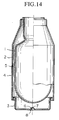
- FIG 14 is provided in order to explain an example of the production method of a conventional metallic evacuated double-walled vessel.
- This figure shows the state of a metallic evacuated double-walled vessel prior to vacuum sealing.
- This prior to vacuum sealing vessel consists of an inner casing 1 which is cylindrical in shape and has a bottom, and an outer casing 4 which consists of a cylindrical outer casing body portion 2 and an outer casing bottom portion 3.
- the mouth portion of outer casing body portion 2 is air tightly joined to the mouth portion of inner casing 1.
- outer casing bottom portion 3 is air tightly joined to the opening at one end of the vessel which is opposite the mouth portion of the outer casing body portion 2.
- a concavity 6 which is indented inward toward inner casing 1 is formed.
- a small hole 7 evacuation hole or slit for evacuation is formed passing through a cavity 5 between the inner casing 1 and the outer casing 4.
- a sealing hot charge 8 such as metallic brazing material, in a paste form is disposed in concavity 6, and the prior-to-sealing vessel is placed in a vacuum heating furnace. Melting and heating of the sealing hot charge 8 is carried out as the inside of the vacuum heating furnace is evacuate to a fixed degree of vacuum. The melted sealing hot charge 8 flows from the periphery therearound into the evacuation hole 7, plugging evacuation hole 7. Following this, sealing hot charge 8 is cooled and hardens, vacuum sealing evacuation hole 7. In this manner, a metallic evacuated double-walled vessel having an evacuated thermal insulating layer between the inner casing 1 and the outer casing 4 is produced (Utility Model Application Hei 2-26837).
- a sealing hot charge 8 in a paste form is disposed about the periphery of concavity 6, the sealing hot charge 8 is melted during vacuum sealing, and flows along the incline of concavity 6 provided to evacuation hole 7, sealing evacuation hole 7. Accordingly, the manner of flow of the melted sealing hot charge 8 changes due to the quantity used, or as a result of the inclination or surface features of the outer casing bottom portion 3 and the concavity 6, the flow of hot charge 8 into evacuation hole 7 becomes unstable, resulting in insufficient sealing. In order to prevent such inconveniences, more sealing hot charge 8 than actually necessary must be used, causing production costs for the vessel to increase.
- Figure 1 is a front cross sectional view of a double-walled vessel prior to sealing, showing a first embodiment of the present invention.
- Figure 2 is a view of the bottom surface of the same prior-to-sealing vessel.
- Figure 3 is a cross sectional view of an essential component of the same prior-to-sealing vessel.
- Figure 4 is a cross sectional view of an essential component showing the state following vacuum sealing of the same vessel.
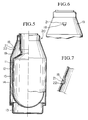
- Figure 5 is a front cross sectional view of a vessel prior to sealing, showing a second embodiment of the present invention.
- Figure 6 is a front view of an essential component of the same prior-to-sealing vessel.
- Figure 7 is a cross sectional view of an essential component of the same prior-to-sealing vessel.
- Figure 8 is a front cross sectional view of a double-walled vessel prior to sealing, showing a third embodiment of the present invention.
- Figure 9 is a view of the bottom surface of the same prior-to-sealing vessel.
- Figure 10 is an enlarged cross sectional view of an essential component of the evacuated double-walled vessel obtained by carrying out vacuum sealing to the same double-walled vessel.
- Figure 11 is a front cross sectional view of a double-walled vessel prior to sealing, showing a fourth embodiment of the present invention.
- Figure 12 is a bottom view showing an enlargement of an essential component of the same double-walled vessel.
- Figure 13 is a front cross sectional view of the double-walled vessel prior to sealing showing a fifth embodiment of the present invention.
- Figure 14 is a front cross sectional view of a prior-to-sealing vessel which is provided to explain the conventional art related to the present invention.
- the present invention was conceived taking into consideration the aforementioned circumstances, and has as its objective the provision of a metallic evacuated double-walled vessel for which it is possible to carry out with surety the placement in an evacuation hole of a sealing hot charge for sealing the evacuation hole, and the sealing of the evacuation hole with the sealing hot charge, at a low cost, thus making possible a reduction in production costs.
- the first invention of the present invention is a production method for a metallic evacuated double-walled vessel characterized in that, in a method for making a metallic evacuated double-walled vessel wherein the vessel consists of a metallic inner and outer vessel and an evacuated thermal insulating layer is formed in the cavity between the inner vessel and the outer vessel, the method comprises the steps of: forming a prior-to-sealing double-walled vessel by joining the mouth portions of the metallic inner and outer vessels to each other in a unitary fashion, forming a concavity in one of either the inner vessel and the outer vessel, and punching an evacuation hole for vacuum evacuation in the concavity; disposing at the time of vacuum heating, a sealing hot charge in a solid form at a position vertically above the evacuation hole leaving a space therebetween; placing the prior-to-sealing vessel in a vacuum heating furnace, and performing vacuum evacuation of the cavity between the inner vessel and the out vessel via the evacuation hole until a fixed degree of vacuum is reached; vacuum sealing the vessel by heating and melting
- This first invention allows vacuum sealing to be carried out with greater surety than that provided by the conventional method wherein vacuum sealing is performed through the flowing of the melted sealing hot charge. Accordingly, by means of this first invention it is possible to lower the rate of defective vacuum sealings, and to improve yield.
- the second invention of the present invention is a production method for a metallic evacuated double-walled vessel characterized in that, in a method for making a metallic evacuated double-walled vessel wherein the vessel consists of a metallic inner and outer vessel and an evacuated thermal insulating layer is formed in the cavity between the inner vessel and the outer vessel, the method comprises the steps of: forming a double-walled vessel by joining together an inner vessel and an outer vessel, one of either the inner vessel and the outer vessel having an evacuation hole; disposing a sealing material consisting of low temperature melting glass, the softening temperature of which is from 200°C to 600°C, in the vicinity of the evacuation opening; placing the double-walled vessel inside a vacuum heating furnace, and vacuum evacuating the cavity between the inner and outer vessels at a temperature lower than the softening temperature of the sealing material; heating the double-walled vessel to a temperature higher than the softening temperature of the sealing material, and sealing the evacuation hole by the allowing the softened sealing material to flow into the evacuation hole.
- the evacuation hole punched in one of either of the inner vessel or the outer vessel of the metallic double-walled vessel is sealed using a sealing material which consists of low temperature melting glass which softens at a temperature of from 200°C to 600°C, it is possible to reduce the temperature for vacuum sealing as compared to the conventional brazing method. For this reason, the temperatures used in the vacuum heating furnace can be lowered, equipment costs are reduced, and the production costs for the article are lowered.
- the low temperature melting glass used in the present invention is advantageous in that, even if oxidants are present on the surface of the metallic double-walled vessel, wettability is not impaired, making it possible to carry out a preferable sealing. Accordingly, it is also possible to omit the process of removing oxidants are removed by heating the surface of the metallic double-walled vessel to a high temperature. Production costs for the evacuated double-walled vessel are thereby further reduced.
- all vacuum evacuation and sealing operations can be carried out at a comparatively low temperatures in the range of from 200°C to 600°C, and the hardness of metallic material such as stainless steel or the like which constructs the vessel can be increased by low temperature annealing.
- the vessel can be made thinner, and the overall weight of the evacuated double-walled vessel can be reduced.
- prior-to-sealing vessel 10 the vessel (hereinafter, referred to as prior-to-sealing vessel 10) shown in Figures 1 through 3 is first prepared.
- This prior-to-sealing vessel 10 consists of a metallic inner casing 11 which is cylindrical in shape and has a bottom, and a metallic outer casing 14 which similarly is cylindrical in shape and has a bottom, the inner casing 11 and outer casing 14 being joined at the mouth portions thereof.
- Outer casing 14 is formed from an outer casing body portion 12 which has a shoulder portion 19 the diameter of which as it approaches the mouth portion gradually reduces in the vicinity of the outer end portion of the mouth portion, and an outer casing bottom portion 13 which is air tightly joined to the opening of outer casing body portion 12 which is opposite the mouth portion thereof.
- Stainless steel is, in particular, preferably used as the metallic material which composes inner casing 11 and outer casing 14.
- a semi-spherical concavity 16 is indented inward toward inner casing 11 at the approximate center portion of outer casing bottom portion 13.
- the diameter Do of concavity 16 is preferably 3 to 15 mm.
- An evacuation hole 17 consisting of a small hole having a diameter A of 0.1 to 2 mm is formed in the approximate center of concavity 16.
- a cylindrical solid sealing hot charge 18 is disposed in concavity 16.
- the diameter d of this solid sealing hot charge 18 is preferably 0.3 to 3 mm, and the length L thereof is within the limits such that A ⁇ L ⁇ Do.
- this solid sealing hot charge 18 is attached in concavity 16 so as to be positioned vertically above evacuation hole 17, with an interval of spacing therebetween.
- the above described prior-to-sealing vessel 10 is contained within a vacuum heating furnace in a state such that the mouth portion is directed downward.
- the vacuum heating process is then carried out. Namely, following vacuum evacuation of cavity 15 to a fixed degree of vacuum via evacuation hole 17 at a temperature below the melting temperature of sealing hot charge 18, the temperature is raised above the melting temperature of sealing hot charge 18, melting sealing hot charge 18 and causing it to drop down onto evacuation hole 17 which is positioned vertically thereunder, and onto the vicinity thereabout.
- FIG. 4 shows the state where evacuation hole 17 has been sealed in this manner by sealing hot charge 18.
- hole diameter A of evacuation hole 17 is less than 0.1 mm, then it is possible that the evacuation of cavity 15 will not be sufficient. Likewise, if hole diameter A is larger than 2.0 mm, due to the surface tension of the melted sealing hot charge 18, it is possible that the hole will not be plugged sufficiently by sealing hot charge 18. Further, provided that sealing hot charge 18 is in a solid form, a metallic brazing material or a low temperature melting glass may also be utilized.
- a metallic evacuated double-walled vessel which consists of metallic inner casing 11 and an outer casing 14 and has an evacuated thermal insulating layer formed between inner casing 11 and outer casing 14, is produced.
- a cylindrical, solid sealing hot charge 18 is attached in concavity 16 so as to be positioned vertically above evacuation hole 17, and the prior-to-sealing vessel 10 is contained then within a vacuum heating furnace.
- cavity 15 is vacuum evacuated to a fixed degree of vacuum via evacuation hole 17 at a temperature below the melting temperature of sealing hot charge 18.
- the temperature is raised above the melting point of sealing hot charge 18, melting sealing hot charge 18 and causing it to drop down under its own weight onto evacuation hole 17 positioned vertically thereunder and onto the vicinity thereabout.
- the position for the provision of concavity 16 is not limited as aforementioned to the outer casing bottom portion 13, but may be provided to the inner casing 11 or to the shoulder portion 19 of outer casing body portion 12, as is the case in a later embodiment.
- the bottom portion of concavity 16 may also be level or inclined.
- the shape of evacuation hole 17 which is punched in concavity 16 may be a slit shaped long hole, or may comprise several small aligned holes. The position at which evacuation hole 17 is punched in concavity 16 is not limited to the approximate center of concavity 16, but may be elsewhere about the vicinity thereof.
- solid sealing hot charge 18 may be other than a cylindrical shape, provided that it is a solid material the length of which is longer than the diameter of evacuation hole 17, and that the shape of which has dimensions which do not interfere with vacuum evacuation when it sealing hot charge 18 disposed directly above evacuation hole 17.
- the cubic volume of sealing hot charge 18 is not limited to a cubic volume as calculated from the above described dimensions. Rather, provided that the cubic volume is with limits which proscribe a minimum value for the cubic volume for the sealing hot charge 18 such that the sealing hot charge 18 has at least a thickness of 0.1 mm and can cover twice the diameter of the minimum cubic volume of evacuation hole 17, and a maximum value for the cubic volume of sealing hot charge 18 such that it does not exceed the inner cubic volume of the concavity so that external impacts are not locally concentrated.
- the prior-to-sealing vessel 20 used in this embodiment differs from the prior-to-sealing vessel 10 used previous embodiment in that a pocket shaped concavity 21 is formed to shoulder portion 19 of the outer casing body portion 12, small evacuation hole 22 is punched in concavity 21, and a cylindrical sealing hot charge 18 is attached vertically above the evacuation hole 22.
- prior-to-sealing vessel 20 is placed upright, namely placed with the mouth portion of the vessel directed upward, and contained within a vacuum heating furnace. Vacuum heating is then carried out.
- cavity 15 is first vacuum evacuated to a fixed degree of vacuum via evacuation hole 22 at a temperature below the melting temperature of sealing hot charge 18. Then, the temperature is raised above the melting temperature of sealing hot charge 18, melting sealing hot charge 18 and causing it to drop down onto evacuation hole 22 which is positioned directly therebelow, and onto the vicinity around evacuation hole 22.
- Sealing hot charge 18 which has dropped down onto evacuation hole 22 and the vicinity therearound collects on evacuation hole 22 and enters into evacuation hole 22 as a result of capillary phenomenon. Following this, sealing hot charge 18 cools and hardens, sealing evacuation hole 22 with surety.
- prior-to-sealing vessel 20 is placed in a vacuum heating furnace with the mouth portion thereof directed upward during vacuum heating, a support device for supporting the prior-to-sealing vessel in the vacuum heating furnace is unnecessary. Thus, the operations of inserting and removing the vessel for vacuum heating are facilitated.
- FIGS 8 through 10 are provided to explain a third embodiment of the production method for a metallic evacuated double-walled vessel according to the present invention.
- the metallic evacuated double-walled vessel produced here is a portable thermos which consists of a stainless steel inner vessel 31 and a stainless steel outer vessel 34 which are joined together, with a cavity 35 between the inner vessel 31 and the outer vessel 34 forming an evacuated thermal insulating layer.
- outer vessel 34 In outer vessel 34, outer vessel bottom member 33 is joined air tightly to the bottom end of approximately cylindrical outer vessel body 32.
- Concavity 40 which is indented to form a semi-spherical shape is formed to the approximate center portion of outer vessel bottom member 33.
- a small evacuation hole 41 is punched in the center of concavity 40.
- the mouth diameter of evacuation hole 41 is preferably 0.1 to 2.0 mm.
- inner vessel 31 and outer vessel body 32 are air tightly joined at the mouth portions thereof, while at the same time, outer vessel bottom member 33 is air tightly joined to outer vessel body 32, forming prior-to-sealing double-walled vessel A (hereinafter, referred to as double-walled vessel).
- double-walled vessel prior-to-sealing double-walled vessel A
- the mouth portion of double-walled vessel A is directed downward, and a rod shaped sealing material 42 is attached inside concavity 40 of outer vessel bottom member 33 with a interval of space maintained between sealing material 42 and evacuation hole 41.
- a low temperature melting glass the softening point of which is from 200°C to 600°C is used in sealing material 42.
- Solder glass derived from B2O3-PbO, B2O3-ZnO, PbO-B2O3-ZnO-SiO2, PbO-B2O3-Al2O3-SiO2, PbO-B2O3-SiO2, or PbO-B2O3-BaO-SiO2 may be used as the low temperature melting glass.
- a material having a coefficient of thermal expansion similar to that of stainless steel which is the material of the double-walled vessel is preferable.
- sealing material 42 may be simply pushed into concavity 40.
- the shape of sealing material 42 is not limited to a rod shape, but may also be a solid shape.
- double-walled vessel A to which sealing material 42 is attached, is transferred to and disposed within a vacuum heating furnace in an inverted position.
- Vacuum heating is carried out by vacuum evacuating the inside of the furnace while heating is performed.
- the temperature for the vacuum heating is set so as to be within the range of 200°C to 600°C and such that sealing material 42 does not soften.
- the gas in the cavity between inner vessel 31 and outer vessel 34 is expelled through evacuation hole 41.
- the temperature inside the furnace is raised to a temperature which is in the range from 200°C to 600°C and which is a temperature above the softening point of sealing material 42.
- Sealing material 42 is softened and drops down under its own weight onto evacuation hole 41 and the vicinity thereabout, sealing evacuation hole 41. Following this vacuum sealing, the vessel is removed from the furnace. As a result, as shown in Figure 10, evacuation hole 41 is sealed with sealing material 42 which consists of low temperature melting glass, thus obtaining a stainless steel thermos (metallic evacuated double-walled vessel) having an evacuated thermal insulating layer 36 between inner vessel 31 and outer vessel 34.
- the double-walled vessel is heated at a temperature in the range of 200°C to 600°C, and the hardness of the stainless steel, which is the material of the double-walled vessel, is increased by low temperature annealing. Accordingly, the thickness of the stainless steel necessary to obtain the required shock and impact resistance is reduced. Thus, the vessel can be made thinner.
- the production method according to the present embodiment by sealing the evacuation hole of the metallic double-walled vessel by using a sealing material consisting of a low temperature melting glass which has a softening temperature in the range of 200° to 600°C, it is possible to reduce the temperature of vacuum sealing as compared to the convention brazing method. For this reason, the temperature utilized within the vacuum heating furnace can be lowered, equipment costs are reduced, and the production costs for the article can be lowered.
- This low temperature melting glass is advantageous in that wettability is not impaired even if oxidants are present on the surface of the double-walled vessel, making it possible to carry out a preferable sealing. Accordingly, it is possible to omit the process for removing oxidants by heating to a high temperature the surface of the double-walled vessel. Thus, the production costs for an evacuated double-walled vessel can be reduced.
- all vacuum evacuation and sealing operations can be carried out at comparatively low temperatures in the range of from 200°C to 600°C, and the hardness of the metallic material such as stainless steel or the like which composes the vessel can be increased by low temperature annealing.
- the vessel can be made thinner, and the overall weight of the evacuated double-walled vessel can be reduced.
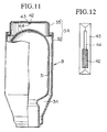
- Figures 11 and 12 are provided to explain a fourth embodiment of the production method for a metallic evacuated double-walled vessel according to the present invention.
- the double-walled vessel B shown in these figures is equipped with almost entirely the same structural elements as those shown in Figures 8 and 9.
- Structural elements shown in Figures 11 and 12 which are identical to those in Figures 8 and 9 have been labeled with the same symbols.
- a long groove 43 is formed in the center portion of the bottom surface side of outer vessel bottom member 33, and a slit-shaped long hole 44 (evacuation hole) is formed in the bottom of long groove 43.
- a rod shaped sealing material 42 consisting of low temperature melting glass and having a length which is shorter than the length of the slit shaped long hole 44 is disposed inside long groove 43 of the double-walled vessel B.
- double-walled vessel B is placed inside a vacuum heating furnace, and vacuum heating is carried out while heating to a temperature which is within the range of 200°C to 600°C and is below the temperature at which sealing material 42 softens.
- the temperature inside the furnace is raised to a temperature which is in the range of from 200°C to 600°C and which is a temperature above the softening point of sealing material 42.
- Sealing material 42 is softened and flows onto slit shaped long hole 44, sealing it, and a stainless steel thermos (evacuated double-walled vessel) is thereby obtained.
- FIG. 13 is provided to explain a fifth embodiment of the production method for a metallic evacuated double-walled vessel according to the present invention.
- the double-walled vessel C shown in these figures is equipped with almost entirely the same structural elements as those shown in Figures 8 and 9. Structural elements shown in Figure 13 which are identical to those in Figures 8 and 9 have been labeled with the same symbols.
- a pocket shaped concavity 40 is provided to the shoulder portion of the outer vessel body 32, and a small evacuation hole 41 is formed inside concavity 40.
- Double-walled vessel C is then placed inside a vacuum heating furnace, and, as in the previous example, vacuum heating is carried out while heating to a temperature which is within the range of 200°C to 600°C and is below the temperature at which sealing material 42 softens. After evacuating to a pressure of 1 x 10 ⁇ 2 torr or less, the temperature inside the furnace is raised to a temperature which is in the range of from 200°C to 600°C and which is above the softening point of sealing material 42.
- Sealing material 42 is softened and drops down under its own weight directly onto evacuation hole 41 and the vicinity therearound, sealing evacuation hole 41. After vacuum sealing, the vessel is removed from the furnace, and a stainless steel thermos (evacuated double-walled vessel) is thereby obtained.
Landscapes
- Engineering & Computer Science (AREA)
- Physics & Mathematics (AREA)
- Thermal Sciences (AREA)
- Mechanical Engineering (AREA)
- Food Science & Technology (AREA)
- General Engineering & Computer Science (AREA)
- Thermally Insulated Containers For Foods (AREA)
Abstract
Description
- The present invention relates to a metallic double-walled vessel such as a portable thermos, pot, jar or the like.
- As a method for producing a metallic evacuated double-walled vessel, there are available such conventional methods as, for example, a method wherein the evacuation of the space between an inner and an outer vessel is carried out by means of a chip tube attached to the outer vessel, and the chip tube is then pressure welded and sealed (Japanese Patent Application, laid open number Sho 59-37914, Japanese Patent Application laid open number Sho 59-103633); a method wherein an evacuation opening is provided to the outer vessel, a brazing metal material is piled around the periphery of the evacuation hole, a sealing member is placed on top of this with an interval of space being maintained between the sealing member and the evacuation hole, heat evacuation is carried out in a vacuum heating furnace, after which, the temperature is raised to the melting temperature of the brazing metal material, the sealing member is brazed, and the vessel is thus vacuum sealed (Japanese Patent Application laid open number Sho 58-192516); and a method wherein a small hole or cut-out is punched in the outer vessel, a brazing metal material is disposed in the vicinity thereof, heat evacuation in a vacuum heating furnace is then performed, the temperature is raised to the melting temperature of the brazing metal material causing the it to melt and flow into the small hole or cut-out, thus vacuum sealing the vessel (Japanese Patent Application Hei 1-106925 (U.S. Patent No. 5,153,977), Utility Model Application Hei 2-26837).
- In the above described method using a chip tube, because the chip tube projects out from the bottom of the outer vessel, it is necessary to attach a bottom cover in order to protect the chip tube. Accordingly, this is problematic because the height of the produced article becomes higher by the length of this protecting cover. Moreover, in the case of large capacity production, because it is necessary to seal and cut the chip tube for each article produced, operations become complicated. Moreover, as it is essential that the process for this sealing technique be highly accurate, great skill is required in the operation. Additionally, the seal is occasionally insufficient, giving rise to the problem that the degree of vacuum deteriorates and the thermal insulating ability is lost over time. Further, in a sealing method using a chip tube, in the case where evacuating the space between the inner and outer vessels, when stimulating the desorption of gas absorbed by the metallic surface by heating the entire vessel, the outer surface of the vessel is exposed to the atmosphere, and a reaction occurs with the oxygen in the atmosphere causing violent oxidation. Because the esthetic appearance and anti-corrosive character of the oxidized surface are impaired, it is necessary to provide a process step to eject such sub-standard articles. Accordingly, costs are increased.
- On the other hand, in a sealing method using brazing material, in order to achieve good wettability of the sealant with respect to the material of the outer vessel, it is necessary to remove any superficial oxidants in the material of the evacuation opening periphery. As a method therefor, there is available a method wherein heating is carried out at a temperature of 950° C or above and at a pressure of 1x10⁻³ torr or less on stainless steel, which is preferably used in, for example, metallic thermoses. In this case, a special vacuum heating furnace of the type which can be used at high temperatures of 950° C and above is necessary. Accordingly, this too is problematic because equipment costs become very expensive.
- Figure 14 is provided in order to explain an example of the production method of a conventional metallic evacuated double-walled vessel. This figure shows the state of a metallic evacuated double-walled vessel prior to vacuum sealing. This prior to vacuum sealing vessel consists of an inner casing 1 which is cylindrical in shape and has a bottom, and an
outer casing 4 which consists of a cylindrical outer casing body portion 2 and an outercasing bottom portion 3. The mouth portion of outer casing body portion 2 is air tightly joined to the mouth portion of inner casing 1. At the same time, outercasing bottom portion 3 is air tightly joined to the opening at one end of the vessel which is opposite the mouth portion of the outer casing body portion 2. Further, in the approximate center of the outercasing bottom portion 3, aconcavity 6 which is indented inward toward inner casing 1 is formed. In the approximate center portion of thisconcavity 6, a small hole 7 (evacuation hole) or slit for evacuation is formed passing through acavity 5 between the inner casing 1 and theouter casing 4. - In order to produce a metallic evacuated double-walled vessel by vacuum sealing this prior-to-sealing vessel, the vessel is inverted with the mouth portion of the prior-to-sealing vessel directed downward, a sealing
hot charge 8, such as metallic brazing material, in a paste form is disposed inconcavity 6, and the prior-to-sealing vessel is placed in a vacuum heating furnace. Melting and heating of the sealinghot charge 8 is carried out as the inside of the vacuum heating furnace is evacuate to a fixed degree of vacuum. The melted sealinghot charge 8 flows from the periphery therearound into theevacuation hole 7, pluggingevacuation hole 7. Following this, sealinghot charge 8 is cooled and hardens, vacuumsealing evacuation hole 7. In this manner, a metallic evacuated double-walled vessel having an evacuated thermal insulating layer between the inner casing 1 and theouter casing 4 is produced (Utility Model Application Hei 2-26837). - However, in this conventional sealing method, a sealing
hot charge 8 in a paste form is disposed about the periphery ofconcavity 6, the sealinghot charge 8 is melted during vacuum sealing, and flows along the incline ofconcavity 6 provided toevacuation hole 7, sealingevacuation hole 7. Accordingly, the manner of flow of the melted sealinghot charge 8 changes due to the quantity used, or as a result of the inclination or surface features of the outercasing bottom portion 3 and theconcavity 6, the flow ofhot charge 8 intoevacuation hole 7 becomes unstable, resulting in insufficient sealing. In order to prevent such inconveniences, more sealinghot charge 8 than actually necessary must be used, causing production costs for the vessel to increase. - Figure 1 is a front cross sectional view of a double-walled vessel prior to sealing, showing a first embodiment of the present invention.
- Figure 2 is a view of the bottom surface of the same prior-to-sealing vessel.
- Figure 3 is a cross sectional view of an essential component of the same prior-to-sealing vessel.
- Figure 4 is a cross sectional view of an essential component showing the state following vacuum sealing of the same vessel.
- Figure 5 is a front cross sectional view of a vessel prior to sealing, showing a second embodiment of the present invention.
- Figure 6 is a front view of an essential component of the same prior-to-sealing vessel.
- Figure 7 is a cross sectional view of an essential component of the same prior-to-sealing vessel.
- Figure 8 is a front cross sectional view of a double-walled vessel prior to sealing, showing a third embodiment of the present invention.
- Figure 9 is a view of the bottom surface of the same prior-to-sealing vessel.
- Figure 10 is an enlarged cross sectional view of an essential component of the evacuated double-walled vessel obtained by carrying out vacuum sealing to the same double-walled vessel.
- Figure 11 is a front cross sectional view of a double-walled vessel prior to sealing, showing a fourth embodiment of the present invention.
- Figure 12 is a bottom view showing an enlargement of an essential component of the same double-walled vessel.
- Figure 13 is a front cross sectional view of the double-walled vessel prior to sealing showing a fifth embodiment of the present invention.
- Figure 14 is a front cross sectional view of a prior-to-sealing vessel which is provided to explain the conventional art related to the present invention.
- The present invention was conceived taking into consideration the aforementioned circumstances, and has as its objective the provision of a metallic evacuated double-walled vessel for which it is possible to carry out with surety the placement in an evacuation hole of a sealing hot charge for sealing the evacuation hole, and the sealing of the evacuation hole with the sealing hot charge, at a low cost, thus making possible a reduction in production costs.
- The first invention of the present invention is a production method for a metallic evacuated double-walled vessel characterized in that, in a method for making a metallic evacuated double-walled vessel wherein the vessel consists of a metallic inner and outer vessel and an evacuated thermal insulating layer is formed in the cavity between the inner vessel and the outer vessel, the method comprises the steps of: forming a prior-to-sealing double-walled vessel by joining the mouth portions of the metallic inner and outer vessels to each other in a unitary fashion, forming a concavity in one of either the inner vessel and the outer vessel, and punching an evacuation hole for vacuum evacuation in the concavity; disposing at the time of vacuum heating, a sealing hot charge in a solid form at a position vertically above the evacuation hole leaving a space therebetween; placing the prior-to-sealing vessel in a vacuum heating furnace, and performing vacuum evacuation of the cavity between the inner vessel and the out vessel via the evacuation hole until a fixed degree of vacuum is reached; vacuum sealing the vessel by heating and melting the sealing hot charge causing the melted sealing hot charge to drop down directly onto the evacuation hole and the vicinity therearound and fill the inside of the evacuation hole, and allowing the sealing hot charge to harden.
- This first invention allows vacuum sealing to be carried out with greater surety than that provided by the conventional method wherein vacuum sealing is performed through the flowing of the melted sealing hot charge. Accordingly, by means of this first invention it is possible to lower the rate of defective vacuum sealings, and to improve yield.
- Moreover, because vacuum sealing is carried out by allowing the melted sealing hot charge to drop directly down into the evacuation hole, such sealing defects as insufficient plugging of the evacuation hole by the sealing hot charge due to the surface tension forces of the sealing hot charge are eliminated, and the quantity of sealing hot charge required may be reduced, thus permitting a reduction in production costs.
- The second invention of the present invention is a production method for a metallic evacuated double-walled vessel characterized in that, in a method for making a metallic evacuated double-walled vessel wherein the vessel consists of a metallic inner and outer vessel and an evacuated thermal insulating layer is formed in the cavity between the inner vessel and the outer vessel, the method comprises the steps of: forming a double-walled vessel by joining together an inner vessel and an outer vessel, one of either the inner vessel and the outer vessel having an evacuation hole; disposing a sealing material consisting of low temperature melting glass, the softening temperature of which is from 200°C to 600°C, in the vicinity of the evacuation opening; placing the double-walled vessel inside a vacuum heating furnace, and vacuum evacuating the cavity between the inner and outer vessels at a temperature lower than the softening temperature of the sealing material; heating the double-walled vessel to a temperature higher than the softening temperature of the sealing material, and sealing the evacuation hole by the allowing the softened sealing material to flow into the evacuation hole.
- In this second invention, because the evacuation hole punched in one of either of the inner vessel or the outer vessel of the metallic double-walled vessel is sealed using a sealing material which consists of low temperature melting glass which softens at a temperature of from 200°C to 600°C, it is possible to reduce the temperature for vacuum sealing as compared to the conventional brazing method. For this reason, the temperatures used in the vacuum heating furnace can be lowered, equipment costs are reduced, and the production costs for the article are lowered. The low temperature melting glass used in the present invention is advantageous in that, even if oxidants are present on the surface of the metallic double-walled vessel, wettability is not impaired, making it possible to carry out a preferable sealing. Accordingly, it is also possible to omit the process of removing oxidants are removed by heating the surface of the metallic double-walled vessel to a high temperature. Production costs for the evacuated double-walled vessel are thereby further reduced.
- Further, when compared to the convention method using a chip tube, it is possible to produce a more compact article as there is no remnant of the chip tube to protrude out. Moreover, with regard to the sealing process, because the treatment in the vacuum heating furnace may be carried out with stability for a large number of articles simultaneously without the introduction of human labor, large capacity production is easily achieved and it is possible to reduce production costs. Moreover, with regard to the process of vacuum evacuation of the space between the inner and outer vessels, because the entire vessel is heated under a vacuum, there is no notable oxidation of the outer surface of the vessel, thus a final removal step may be omitted. Costs can therefore be reduced.
- Further, all vacuum evacuation and sealing operations can be carried out at a comparatively low temperatures in the range of from 200°C to 600°C, and the hardness of metallic material such as stainless steel or the like which constructs the vessel can be increased by low temperature annealing. As a result, using a metallic material having a high degree of hardness, the vessel can be made thinner, and the overall weight of the evacuated double-walled vessel can be reduced.
- In the production method for a metallic evacuated double-walled vessel according to this embodiment, prior to vacuum sealing, the vessel (hereinafter, referred to as prior-to-sealing vessel 10) shown in Figures 1 through 3 is first prepared.
- This prior-to-sealing
vessel 10 consists of a metallic inner casing 11 which is cylindrical in shape and has a bottom, and a metallicouter casing 14 which similarly is cylindrical in shape and has a bottom, the inner casing 11 andouter casing 14 being joined at the mouth portions thereof.Outer casing 14 is formed from an outercasing body portion 12 which has ashoulder portion 19 the diameter of which as it approaches the mouth portion gradually reduces in the vicinity of the outer end portion of the mouth portion, and an outercasing bottom portion 13 which is air tightly joined to the opening of outercasing body portion 12 which is opposite the mouth portion thereof. Stainless steel is, in particular, preferably used as the metallic material which composes inner casing 11 andouter casing 14. - A
semi-spherical concavity 16 is indented inward toward inner casing 11 at the approximate center portion of outercasing bottom portion 13. The diameter Do ofconcavity 16 is preferably 3 to 15 mm. Anevacuation hole 17 consisting of a small hole having a diameter A of 0.1 to 2 mm is formed in the approximate center ofconcavity 16. Furthermore, a cylindrical solid sealinghot charge 18 is disposed inconcavity 16. The diameter d of this solid sealinghot charge 18 is preferably 0.3 to 3 mm, and the length L thereof is within the limits such that A < L < Do. - In the state for vacuum heating prior-to-sealing
vessel 10, namely in the state where the opening of the vessel is directed downward, this solid sealinghot charge 18 is attached inconcavity 16 so as to be positioned vertically aboveevacuation hole 17, with an interval of spacing therebetween. - Next, a metallic double-walled vessel is produced by vacuum sealing prior-to-sealing
vessel 10. - The above described prior-to-sealing
vessel 10 is contained within a vacuum heating furnace in a state such that the mouth portion is directed downward. The vacuum heating process is then carried out. Namely, following vacuum evacuation ofcavity 15 to a fixed degree of vacuum viaevacuation hole 17 at a temperature below the melting temperature of sealinghot charge 18, the temperature is raised above the melting temperature of sealinghot charge 18, melting sealinghot charge 18 and causing it to drop down ontoevacuation hole 17 which is positioned vertically thereunder, and onto the vicinity thereabout. - Sealing
hot charge 18 which has dropped down ontoevacuation hole 17 and the vicinity thereof collects onevacuation hole 17, and enters withinevacuation hole 17 as a result of capillary phenomenon. Following this, sealinghot charge 18 cools and hardens, sealingevacuation hole 17 with surety. Figure 4 shows the state whereevacuation hole 17 has been sealed in this manner by sealinghot charge 18. - If hole diameter A of
evacuation hole 17 is less than 0.1 mm, then it is possible that the evacuation ofcavity 15 will not be sufficient. Likewise, if hole diameter A is larger than 2.0 mm, due to the surface tension of the melted sealinghot charge 18, it is possible that the hole will not be plugged sufficiently by sealinghot charge 18. Further, provided that sealinghot charge 18 is in a solid form, a metallic brazing material or a low temperature melting glass may also be utilized. - As described above, a metallic evacuated double-walled vessel which consists of metallic inner casing 11 and an
outer casing 14 and has an evacuated thermal insulating layer formed between inner casing 11 andouter casing 14, is produced. - In this embodiment, in the state for vacuum heating prior-to-sealing
vessel 10, in other words in the state where the opening of the vessel is directed downward, a cylindrical, solid sealinghot charge 18 is attached inconcavity 16 so as to be positioned vertically aboveevacuation hole 17, and the prior-to-sealingvessel 10 is contained then within a vacuum heating furnace. First,cavity 15 is vacuum evacuated to a fixed degree of vacuum viaevacuation hole 17 at a temperature below the melting temperature of sealinghot charge 18. Following this, the temperature is raised above the melting point of sealinghot charge 18, melting sealinghot charge 18 and causing it to drop down under its own weight ontoevacuation hole 17 positioned vertically thereunder and onto the vicinity thereabout. By carrying out vacuum sealing in this manner, it is possible to carry out vacuum sealing with greater surety than that provided by conventional methods of vacuum sealing which rely on the flow of a paste form melted sealing hot charge. Moreover, it is also possible to improve product yield by reducing the rate at which defective vacuum sealings arise. Further, because the melted sealinghot charge 18 drops directly down ontoevacuation hole 17, vacuum sealing it, such sealing defects as sealinghot charge 18 not pluggingevacuation hole 17 sufficiently due to the surface tension of the melted sealinghot charge 18 are eliminated, and the amount of sealinghot charge 18 used can be reduced. Thus, product costs can be lowered. - Additionally, the position for the provision of
concavity 16 is not limited as aforementioned to the outercasing bottom portion 13, but may be provided to the inner casing 11 or to theshoulder portion 19 of outercasing body portion 12, as is the case in a later embodiment. Further, in addition to being a curved concavity such as in the preceding embodiment, the bottom portion ofconcavity 16 may also be level or inclined. Moreover, the shape ofevacuation hole 17 which is punched inconcavity 16 may be a slit shaped long hole, or may comprise several small aligned holes. The position at whichevacuation hole 17 is punched inconcavity 16 is not limited to the approximate center ofconcavity 16, but may be elsewhere about the vicinity thereof. Furthermore, solid sealinghot charge 18 may be other than a cylindrical shape, provided that it is a solid material the length of which is longer than the diameter ofevacuation hole 17, and that the shape of which has dimensions which do not interfere with vacuum evacuation when it sealinghot charge 18 disposed directly aboveevacuation hole 17. Moreover, the cubic volume of sealinghot charge 18 is not limited to a cubic volume as calculated from the above described dimensions. Rather, provided that the cubic volume is with limits which proscribe a minimum value for the cubic volume for the sealinghot charge 18 such that the sealinghot charge 18 has at least a thickness of 0.1 mm and can cover twice the diameter of the minimum cubic volume ofevacuation hole 17, and a maximum value for the cubic volume of sealinghot charge 18 such that it does not exceed the inner cubic volume of the concavity so that external impacts are not locally concentrated. - The prior-to-sealing
vessel 20 used in this embodiment differs from the prior-to-sealingvessel 10 used previous embodiment in that a pocket shapedconcavity 21 is formed toshoulder portion 19 of the outercasing body portion 12,small evacuation hole 22 is punched inconcavity 21, and a cylindrical sealinghot charge 18 is attached vertically above theevacuation hole 22. - Because, with prior-to-sealing
vessel 20 in an upright state, solid sealinghot charge 18 is positioned vertically aboveevacuation hole 22 with spacing therebetween, in order to carry out vacuum sealing of prior-to-sealingvessel 20, prior-to-sealingvessel 20 is placed upright, namely placed with the mouth portion of the vessel directed upward, and contained within a vacuum heating furnace. Vacuum heating is then carried out. In this vacuum heating treatment,cavity 15 is first vacuum evacuated to a fixed degree of vacuum viaevacuation hole 22 at a temperature below the melting temperature of sealinghot charge 18. Then, the temperature is raised above the melting temperature of sealinghot charge 18, melting sealinghot charge 18 and causing it to drop down ontoevacuation hole 22 which is positioned directly therebelow, and onto the vicinity aroundevacuation hole 22. Sealinghot charge 18 which has dropped down ontoevacuation hole 22 and the vicinity therearound collects onevacuation hole 22 and enters intoevacuation hole 22 as a result of capillary phenomenon. Following this, sealinghot charge 18 cools and hardens, sealingevacuation hole 22 with surety. - In the production method according to this embodiment, in addition to obtaining the same effects as those obtained in the previous embodiment, because prior-to-sealing
vessel 20 is placed in a vacuum heating furnace with the mouth portion thereof directed upward during vacuum heating, a support device for supporting the prior-to-sealing vessel in the vacuum heating furnace is unnecessary. Thus, the operations of inserting and removing the vessel for vacuum heating are facilitated. - Figures 8 through 10 are provided to explain a third embodiment of the production method for a metallic evacuated double-walled vessel according to the present invention. The metallic evacuated double-walled vessel produced here is a portable thermos which consists of a stainless steel
inner vessel 31 and a stainless steelouter vessel 34 which are joined together, with acavity 35 between theinner vessel 31 and theouter vessel 34 forming an evacuated thermal insulating layer. - In
outer vessel 34, outervessel bottom member 33 is joined air tightly to the bottom end of approximately cylindricalouter vessel body 32.Concavity 40 which is indented to form a semi-spherical shape is formed to the approximate center portion of outervessel bottom member 33. Asmall evacuation hole 41 is punched in the center ofconcavity 40. The mouth diameter ofevacuation hole 41 is preferably 0.1 to 2.0 mm. - In order to produce this thermos,
inner vessel 31 andouter vessel body 32 are air tightly joined at the mouth portions thereof, while at the same time, outervessel bottom member 33 is air tightly joined toouter vessel body 32, forming prior-to-sealing double-walled vessel A (hereinafter, referred to as double-walled vessel). Next, as is shown in Figures 8 and 9, the mouth portion of double-walled vessel A is directed downward, and a rod shaped sealingmaterial 42 is attached insideconcavity 40 of outervessel bottom member 33 with a interval of space maintained between sealingmaterial 42 andevacuation hole 41. - A low temperature melting glass, the softening point of which is from 200°C to 600°C is used in sealing
material 42. Solder glass derived from B₂O₃-PbO, B₂O₃-ZnO, PbO-B₂O₃-ZnO-SiO₂, PbO-B₂O₃-Al₂O₃-SiO₂, PbO-B₂O₃-SiO₂, or PbO-B₂O₃-BaO-SiO₂ may be used as the low temperature melting glass. In particular, a material having a coefficient of thermal expansion similar to that of stainless steel which is the material of the double-walled vessel is preferable. - To attach rod shaped sealing
material 42 inconcavity 40, sealingmaterial 42 may be simply pushed intoconcavity 40. However, in order to prevent positional displacement of sealingmaterial 42, it is also possible to coat an adhesive agent to both ends of sealingmaterial 42 and thereby fix it firmly insideconcavity 40. Moreover, the shape of sealingmaterial 42 is not limited to a rod shape, but may also be a solid shape. - Next, double-walled vessel A, to which sealing
material 42 is attached, is transferred to and disposed within a vacuum heating furnace in an inverted position. Vacuum heating is carried out by vacuum evacuating the inside of the furnace while heating is performed. The temperature for the vacuum heating is set so as to be within the range of 200°C to 600°C and such that sealingmaterial 42 does not soften. The gas in the cavity betweeninner vessel 31 andouter vessel 34 is expelled throughevacuation hole 41. After evacuating to a pressure of 1 x 10⁻² torr or less, the temperature inside the furnace is raised to a temperature which is in the range from 200°C to 600°C and which is a temperature above the softening point of sealingmaterial 42. Sealingmaterial 42 is softened and drops down under its own weight ontoevacuation hole 41 and the vicinity thereabout, sealingevacuation hole 41. Following this vacuum sealing, the vessel is removed from the furnace. As a result, as shown in Figure 10,evacuation hole 41 is sealed with sealingmaterial 42 which consists of low temperature melting glass, thus obtaining a stainless steel thermos (metallic evacuated double-walled vessel) having an evacuated thermal insulatinglayer 36 betweeninner vessel 31 andouter vessel 34. - Via this vacuum sealing process, the double-walled vessel is heated at a temperature in the range of 200°C to 600°C, and the hardness of the stainless steel, which is the material of the double-walled vessel, is increased by low temperature annealing. Accordingly, the thickness of the stainless steel necessary to obtain the required shock and impact resistance is reduced. Thus, the vessel can be made thinner.
- In the production method according to the present embodiment, by sealing the evacuation hole of the metallic double-walled vessel by using a sealing material consisting of a low temperature melting glass which has a softening temperature in the range of 200° to 600°C, it is possible to reduce the temperature of vacuum sealing as compared to the convention brazing method. For this reason, the temperature utilized within the vacuum heating furnace can be lowered, equipment costs are reduced, and the production costs for the article can be lowered. This low temperature melting glass is advantageous in that wettability is not impaired even if oxidants are present on the surface of the double-walled vessel, making it possible to carry out a preferable sealing. Accordingly, it is possible to omit the process for removing oxidants by heating to a high temperature the surface of the double-walled vessel. Thus, the production costs for an evacuated double-walled vessel can be reduced.
- Further, when compared to the convention method using a chip tube, it is possible to produce a more compact product as there is no remnant of the chip tube to protrude out. Moreover, with regard to the sealing process, because treatment in the vacuum heating furnace may be carried out with stability for a large number of articles simultaneously without the introduction of human labor, large capacity production is easily achieved and it is possible to reduce production costs. Moreover, with regard to the process of vacuum evacuation of the space between the inner and outer vessels, because the entire vessel is heated under a vacuum, there is no notable oxidation of the outer surface of the vessel, therefore, a final removal process can be omitted. Thus, costs can be reduced.
- Further, all vacuum evacuation and sealing operations can be carried out at comparatively low temperatures in the range of from 200°C to 600°C, and the hardness of the metallic material such as stainless steel or the like which composes the vessel can be increased by low temperature annealing. As a result, using a metallic material having a high degree of hardness, the vessel can be made thinner, and the overall weight of the evacuated double-walled vessel can be reduced.
- Figures 11 and 12 are provided to explain a fourth embodiment of the production method for a metallic evacuated double-walled vessel according to the present invention. The double-walled vessel B shown in these figures is equipped with almost entirely the same structural elements as those shown in Figures 8 and 9. Structural elements shown in Figures 11 and 12 which are identical to those in Figures 8 and 9 have been labeled with the same symbols. In the double-walled vessel B shown in Figures 11 and 12, a
long groove 43 is formed in the center portion of the bottom surface side of outervessel bottom member 33, and a slit-shaped long hole 44 (evacuation hole) is formed in the bottom oflong groove 43. As is shown in Figure 12, a rod shaped sealingmaterial 42 consisting of low temperature melting glass and having a length which is shorter than the length of the slit shapedlong hole 44 is disposed insidelong groove 43 of the double-walled vessel B. Following this, as in the previous example, double-walled vessel B is placed inside a vacuum heating furnace, and vacuum heating is carried out while heating to a temperature which is within the range of 200°C to 600°C and is below the temperature at which sealingmaterial 42 softens. After evacuating to a pressure of 1 x 10⁻² torr or less, the temperature inside the furnace is raised to a temperature which is in the range of from 200°C to 600°C and which is a temperature above the softening point of sealingmaterial 42. Sealingmaterial 42 is softened and flows onto slit shapedlong hole 44, sealing it, and a stainless steel thermos (evacuated double-walled vessel) is thereby obtained. - Figures 13 is provided to explain a fifth embodiment of the production method for a metallic evacuated double-walled vessel according to the present invention. The double-walled vessel C shown in these figures is equipped with almost entirely the same structural elements as those shown in Figures 8 and 9. Structural elements shown in Figure 13 which are identical to those in Figures 8 and 9 have been labeled with the same symbols. In the double-walled vessel C shown in Figure 13, a pocket shaped
concavity 40 is provided to the shoulder portion of theouter vessel body 32, and asmall evacuation hole 41 is formed insideconcavity 40. - To seal this double-walled vessel C, the opening of double-walled vessel C is directed upward, and a rod shaped sealing
material 42 consisting of low temperature melting glass and is attached insideconcavity 40. Double-walled vessel C is then placed inside a vacuum heating furnace, and, as in the previous example, vacuum heating is carried out while heating to a temperature which is within the range of 200°C to 600°C and is below the temperature at which sealingmaterial 42 softens. After evacuating to a pressure of 1 x 10⁻² torr or less, the temperature inside the furnace is raised to a temperature which is in the range of from 200°C to 600°C and which is above the softening point of sealingmaterial 42. Sealingmaterial 42 is softened and drops down under its own weight directly ontoevacuation hole 41 and the vicinity therearound, sealingevacuation hole 41. After vacuum sealing, the vessel is removed from the furnace, and a stainless steel thermos (evacuated double-walled vessel) is thereby obtained.
Claims (9)
- A method for making a metallic evacuated double-walled vessel wherein said vessel consists of metallic inner and outer vessels and the space between said inner vessel and said outer vessel forms an evacuated thermal insulating layer, the method comprising the steps of:(a) forming a prior-to-sealing double-walled vessel by joining said metallic inner vessel and said metallic outer unitarily together at the respective mouth portions thereof, forming a concavity in one of either said inner vessel and said outer vessel, and punching inside said concavity an evacuation hole through which to carry out vacuum evacuation;(b) disposing prior to vacuum heating a solid shaped sealing material at a position directly above said evacuation hole of said prior-to-sealing double-walled vessel with an interval of space therebetween;(c) placing said prior-to-sealing double-walled vessel inside a vacuum heating furnace, and vacuum evacuating via said evacuation hole said cavity between said inner vessel and said outer vessel to a specified degree of evacuation; and(d) carrying out vacuum sealing by heating and melting said sealing material, causing said melted sealing material to drop down onto and fill said evacuation hole and the vicinity thereabout, and hardening said sealing material.
- A method for making a metallic evacuated double-walled vessel according to claim 1, wherein, a concavity and an evacuation hole are formed in the bottom portion of the outer vessel of a double-walled vessel, a sealing hot charge comprising one of either a solid brazing material and a low temperature melting glass is disposed within said concavity at a position so as to be directly above said evacuation hole when said double-walled vessel is inverted with an interval of spacing being maintained between said sealing hot charge and said evacuation hole, said double-walled vessel is inverted so that the mouth portion thereof is directed downward and is placed in a vacuum heating furnace, and vacuum evacuation and vacuum sealing are carried out.
- A method for making a metallic evacuated double-walled vessel according to claim 1, wherein a concavity and an evacuation hole are formed in the shoulder portion of the outer vessel of a double-walled vessel, a sealing hot charge comprising one of either a solid brazing material and a low temperature melting glass is disposed within said concavity at a position so as to be directly above said evacuation hole with an interval of spacing being maintained between said sealing hot charge and said evacuation hole, said double-walled vessel is placed upright so that the mouth portion thereof is directed upward in a vacuum heating furnace, and vacuum evacuation and vacuum sealing are carried out.
- A metallic evacuated double-walled vessel produced by a method for making a metallic evacuated double-walled vessel according to one of claims one through 3.
- A method for making a metallic evacuated double-walled vessel wherein said vessel consists of metallic inner and outer vessels and the space between said inner vessel and said outer vessel forms an evacuated thermal insulating layer, the method comprising the steps of:(a) forming a double-walled vessel by joining together said inner vessel and said outer vessel, one of either said inner vessel and said outer vessel having an evacuation hole;(b) disposing a sealing material consisting of a low temperature melting glass having a softening temperature in the range of 200°C to 600°C to the vicinity of said evacuation hole;(c) placing said double-walled vessel inside a vacuum heating furnace, and vacuum evacuating the cavity between said inner vessel and said outer vessel at a temperature lower than the softening temperature of said sealing material;(d) heating said double-walled vessel to a temperature above the softening temperature of said sealing material, causing said sealing material to melt and flow into said evacuation hole, to seal said evacuation hole.
- A method for making a metallic evacuated double-walled vessel according to claim 5, wherein, a concavity and an evacuation hole are formed in the bottom portion of said outer vessel of said double-walled vessel, a sealing material comprising low temperature melting glass is disposed within said concavity at a position so as to be directly above said evacuation hole when said double-walled vessel is inverted with an interval of spacing being maintained between said sealing material and said evacuation hole, said double-walled vessel is inverted so that the mouth portion thereof is directed downward and is placed in a vacuum heating furnace, and vacuum evacuation and vacuum sealing are carried out.
- A method for making a metallic evacuated double-walled vessel according to claim 5, wherein a long groove is formed in the bottom portion of said outer vessel of said double-walled vessel and a slit shaped long hole is formed in the bottom of said long groove, said double-walled vessel is inverted so that the mouth portion thereof is directed downward, a rod shaped sealing material comprising low temperature melting glass is inserted inside said long groove, said double-walled vessel is placed inverted inside a vacuum heating furnace, and vacuum evacuation and vacuum heating are carried out.
- A method for making a metallic evacuated double-walled vessel according to claim 1, wherein a concavity and an evacuation hole are formed in the shoulder portion of said outer vessel of said double-walled vessel, a low temperature melting glass sealing hot charge is disposed within said concavity at a position so as to be directly above said evacuation hole with an interval of spacing being maintained between said low temperature melting glass sealing hot charge and said evacuation hole, said double-walled vessel is placed upright so that the mouth portion thereof is directed upward in a vacuum heating furnace, and vacuum evacuation and vacuum sealing are carried out.
- A metallic evacuated double-walled vessel, said vessel consisting of metallic inner and outer vessels and the space between said inner vessel and said outer vessel forming an evacuated thermal insulating layer, wherein an evacuation hole formed in one of either said inner vessel and said outer vessel is vacuum sealed with a sealing material consisting of low temperature melting glass which softens at a temperature of from 200°C to 600°C.
Priority Applications (1)
| Application Number | Priority Date | Filing Date | Title |
|---|---|---|---|
| EP96202986A EP0755646B1 (en) | 1992-11-12 | 1993-11-09 | Metallic evacuated double-walled vessel and production method therefor |
Applications Claiming Priority (4)
| Application Number | Priority Date | Filing Date | Title |
|---|---|---|---|
| JP4302621A JP2774746B2 (en) | 1992-11-12 | 1992-11-12 | Manufacturing method of metal vacuum double container |
| JP302621/92 | 1992-11-12 | ||
| JP4327048A JP2774748B2 (en) | 1992-12-07 | 1992-12-07 | Metal vacuum double container and method of manufacturing the same |
| JP327048/92 | 1992-12-07 |
Related Child Applications (1)
| Application Number | Title | Priority Date | Filing Date |
|---|---|---|---|
| EP96202986A Division EP0755646B1 (en) | 1992-11-12 | 1993-11-09 | Metallic evacuated double-walled vessel and production method therefor |
Publications (2)
| Publication Number | Publication Date |
|---|---|
| EP0597773A1 true EP0597773A1 (en) | 1994-05-18 |
| EP0597773B1 EP0597773B1 (en) | 1998-04-22 |
Family
ID=26563196
Family Applications (2)
| Application Number | Title | Priority Date | Filing Date |
|---|---|---|---|
| EP96202986A Expired - Lifetime EP0755646B1 (en) | 1992-11-12 | 1993-11-09 | Metallic evacuated double-walled vessel and production method therefor |
| EP93402745A Expired - Lifetime EP0597773B1 (en) | 1992-11-12 | 1993-11-09 | Method for producing a metallic evacuated double-walled vessel |
Family Applications Before (1)
| Application Number | Title | Priority Date | Filing Date |
|---|---|---|---|
| EP96202986A Expired - Lifetime EP0755646B1 (en) | 1992-11-12 | 1993-11-09 | Metallic evacuated double-walled vessel and production method therefor |
Country Status (7)
| Country | Link |
|---|---|
| EP (2) | EP0755646B1 (en) |
| KR (1) | KR100250778B1 (en) |
| CN (1) | CN1053804C (en) |
| DE (2) | DE69318107T2 (en) |
| HK (1) | HK1009926A1 (en) |
| MY (1) | MY109618A (en) |
| SG (1) | SG47681A1 (en) |
Cited By (5)
| Publication number | Priority date | Publication date | Assignee | Title |
|---|---|---|---|---|
| GB2404911A (en) * | 2003-08-15 | 2005-02-16 | Stephen Tew | Insulated containers |
| US7383964B2 (en) | 2003-08-13 | 2008-06-10 | Cool-System Bev. Gmbh | Container with at least one vacuum chamber with an access opening especially a beverage container, such as a beer barrel on the like |
| BE1023257B1 (en) * | 2015-12-22 | 2017-01-12 | Allibert Hovac Nv | Glass container for an insulating bottle |
| CN107477352A (en) * | 2017-09-13 | 2017-12-15 | 云南电网有限责任公司电力科学研究院 | A kind of hot low-temperature (low temperature) vessel of low drain |
| WO2019007099A1 (en) * | 2017-07-01 | 2019-01-10 | 佛山市铠斯钛科技有限公司 | Novel method for manufacturing vacuum heat-insulating container, and vacuum heat-insulating container manufactured thereby |
Families Citing this family (9)
| Publication number | Priority date | Publication date | Assignee | Title |
|---|---|---|---|---|
| JP2000005083A (en) * | 1998-04-23 | 2000-01-11 | Nippon Sanso Kk | Metallic vacuum double wall container and its manufacture |
| KR20040011223A (en) * | 2002-07-29 | 2004-02-05 | 원제돈 | vacuum thermos and manufacturing method thereof |
| DE102004010816B4 (en) * | 2003-08-13 | 2005-08-04 | Cool-System Bev. Gmbh | Container with at least one vacuum chamber with an access opening, in particular beverage container such as beer keg or the like |
| KR101415603B1 (en) * | 2013-01-16 | 2014-08-06 | 이영희 | Method of a vacuum sealing with hot well for a water purifier |
| WO2017136747A1 (en) * | 2016-02-05 | 2017-08-10 | Yeti Coolers, Llc | Insulating container and method of forming such a container |
| CN107380740B (en) * | 2017-07-01 | 2019-08-06 | 佛山市铠斯钛科技有限公司 | A kind of efficient cool-bag manufacturing method and its cool-bag of manufacture |
| CN107380741B (en) * | 2017-07-01 | 2019-09-10 | 佛山市铠斯钛科技有限公司 | A kind of manufacturing method of the strong cool-bag of air-tightness and its cool-bag of manufacture |
| CA3072166A1 (en) * | 2017-07-07 | 2019-01-10 | Concept Group Llc | Joint configurations for vacuum-insulated articles |
| CN109465601A (en) * | 2018-11-13 | 2019-03-15 | 西安庄信新材料科技有限公司 | A kind of method of titanium seamless tubes production titanium vacuum cup |
Citations (6)
| Publication number | Priority date | Publication date | Assignee | Title |
|---|---|---|---|---|
| US3953757A (en) * | 1975-02-26 | 1976-04-27 | Robert Johan Ney | Solder sealed light bulb |
| US4251252A (en) * | 1978-06-23 | 1981-02-17 | Aladdin Industries, Incorporated | Method for making vacuum insulated container |
| JPS61228688A (en) * | 1985-04-02 | 1986-10-11 | Nec Corp | Inner mirror type gas laser tube |
| JPH02215416A (en) * | 1989-02-16 | 1990-08-28 | Nippon Sanso Kk | Manufacture of metallic thermos bottle |
| JPH03267023A (en) * | 1990-03-16 | 1991-11-27 | Nippon Sanso Kk | Manufacture of metallic vacuum bottle |
| EP0497064A1 (en) * | 1991-02-01 | 1992-08-05 | Nippon Sanso Corporation | Method for making double-walled insulating metal container |
Family Cites Families (1)
| Publication number | Priority date | Publication date | Assignee | Title |
|---|---|---|---|---|
| US4251595A (en) * | 1979-09-10 | 1981-02-17 | Technology Glass Corporation | Low temperature sealing glasses |
-
1993
- 1993-11-09 SG SG1996003695A patent/SG47681A1/en unknown
- 1993-11-09 DE DE69318107T patent/DE69318107T2/en not_active Expired - Fee Related
- 1993-11-09 DE DE69332035T patent/DE69332035T2/en not_active Expired - Fee Related
- 1993-11-09 EP EP96202986A patent/EP0755646B1/en not_active Expired - Lifetime
- 1993-11-09 EP EP93402745A patent/EP0597773B1/en not_active Expired - Lifetime
- 1993-11-10 MY MYPI93002353A patent/MY109618A/en unknown
- 1993-11-11 KR KR1019930023911A patent/KR100250778B1/en not_active IP Right Cessation
- 1993-11-12 CN CN93112907A patent/CN1053804C/en not_active Expired - Lifetime
-
1998
- 1998-09-22 HK HK98110809A patent/HK1009926A1/en not_active IP Right Cessation
Patent Citations (8)
| Publication number | Priority date | Publication date | Assignee | Title |
|---|---|---|---|---|
| US3953757A (en) * | 1975-02-26 | 1976-04-27 | Robert Johan Ney | Solder sealed light bulb |
| US4251252A (en) * | 1978-06-23 | 1981-02-17 | Aladdin Industries, Incorporated | Method for making vacuum insulated container |
| JPS61228688A (en) * | 1985-04-02 | 1986-10-11 | Nec Corp | Inner mirror type gas laser tube |
| JPH02215416A (en) * | 1989-02-16 | 1990-08-28 | Nippon Sanso Kk | Manufacture of metallic thermos bottle |
| JPH03267023A (en) * | 1990-03-16 | 1991-11-27 | Nippon Sanso Kk | Manufacture of metallic vacuum bottle |
| EP0497064A1 (en) * | 1991-02-01 | 1992-08-05 | Nippon Sanso Corporation | Method for making double-walled insulating metal container |
| US5153977A (en) * | 1991-02-01 | 1992-10-13 | Nippon Sanso Corporation | Method for making double-walled insulating metal container |
| US5153977B1 (en) * | 1991-02-01 | 1998-07-28 | Nippon Oxygen Co Ltd | Method for making double-walled insulating metal container |
Non-Patent Citations (3)
| Title |
|---|
| PATENT ABSTRACTS OF JAPAN vol. 011, no. 073 (E - 486) 5 March 1987 (1987-03-05) * |
| PATENT ABSTRACTS OF JAPAN vol. 014, no. 522 (C - 0778) 15 November 1990 (1990-11-15) * |
| PATENT ABSTRACTS OF JAPAN vol. 016, no. 076 (C - 0914) 25 February 1992 (1992-02-25) * |
Cited By (7)
| Publication number | Priority date | Publication date | Assignee | Title |
|---|---|---|---|---|
| US7383964B2 (en) | 2003-08-13 | 2008-06-10 | Cool-System Bev. Gmbh | Container with at least one vacuum chamber with an access opening especially a beverage container, such as a beer barrel on the like |
| GB2404911A (en) * | 2003-08-15 | 2005-02-16 | Stephen Tew | Insulated containers |
| GB2404911B (en) * | 2003-08-15 | 2006-09-20 | Stephen Tew | Containers |
| BE1023257B1 (en) * | 2015-12-22 | 2017-01-12 | Allibert Hovac Nv | Glass container for an insulating bottle |
| WO2017108769A1 (en) * | 2015-12-22 | 2017-06-29 | Allibert Hovac | Glass container for an insulating flask |
| WO2019007099A1 (en) * | 2017-07-01 | 2019-01-10 | 佛山市铠斯钛科技有限公司 | Novel method for manufacturing vacuum heat-insulating container, and vacuum heat-insulating container manufactured thereby |
| CN107477352A (en) * | 2017-09-13 | 2017-12-15 | 云南电网有限责任公司电力科学研究院 | A kind of hot low-temperature (low temperature) vessel of low drain |
Also Published As
| Publication number | Publication date |
|---|---|
| EP0755646A2 (en) | 1997-01-29 |
| KR940011090A (en) | 1994-06-20 |
| DE69318107T2 (en) | 1998-10-22 |
| DE69332035T2 (en) | 2003-01-30 |
| EP0755646A3 (en) | 1997-06-11 |
| DE69318107D1 (en) | 1998-05-28 |
| MY109618A (en) | 1997-03-31 |
| EP0597773B1 (en) | 1998-04-22 |
| KR100250778B1 (en) | 2000-04-01 |
| EP0755646B1 (en) | 2002-06-12 |
| SG47681A1 (en) | 1998-04-17 |
| HK1009926A1 (en) | 1999-06-11 |
| DE69332035D1 (en) | 2002-07-18 |
| CN1117834A (en) | 1996-03-06 |
| CN1053804C (en) | 2000-06-28 |
Similar Documents
| Publication | Publication Date | Title |
|---|---|---|
| EP0597773A1 (en) | Metallic evacuated double-walled vessel and production method therefor | |
| EP0497064A1 (en) | Method for making double-walled insulating metal container | |
| US4183456A (en) | Method of fabricating liquid cooled gas turbine components | |
| US4251252A (en) | Method for making vacuum insulated container | |
| US6623593B2 (en) | Method of forming an outlet structure of sealed container having a hollow member with a flare-shaped opening portion | |
| JP2774748B2 (en) | Metal vacuum double container and method of manufacturing the same | |
| CN107378166A (en) | A kind of sealing technique for reducing electronic component cover plate sealing cavity | |
| JPS61106119A (en) | Production of vacuum double container made of stainless steel | |
| JP2845375B2 (en) | Manufacturing method of metal thermos | |
| JP2774592B2 (en) | Manufacturing method of metal thermos | |
| JP2774746B2 (en) | Manufacturing method of metal vacuum double container | |
| CN207587715U (en) | One kind is suitable for surface mount IC chip positioning fixture and combines | |
| JPH0698109B2 (en) | Metal vacuum double structure and manufacturing method thereof | |
| JPH0698108B2 (en) | Metal vacuum double structure and manufacturing method thereof | |
| JP2637346B2 (en) | Metal vacuum double container and manufacturing method thereof | |
| JPH0719402Y2 (en) | Metal thermos | |
| JPS61106120A (en) | Production of vacuum double container made of stainless steel | |
| JPS5931157Y2 (en) | metal thermos flask | |
| JPH0314112Y2 (en) | ||
| JPH078395A (en) | Metal made vacuum double layer container and the manufacture thereof | |
| CN117690807A (en) | AuSn melt sealing process method | |
| JPS58192516A (en) | Production of metal magic pot | |
| JPS59196529A (en) | Manufacture of flash discharge lamp | |
| HUT66318A (en) | Method for manufacturing electrochemical sensors made of metal and the sensor made by said method | |
| JPH05176846A (en) | Production of heat-insulated vessel |
Legal Events
| Date | Code | Title | Description |
|---|---|---|---|
| PUAI | Public reference made under article 153(3) epc to a published international application that has entered the european phase |
Free format text: ORIGINAL CODE: 0009012 |
|
| AK | Designated contracting states |
Kind code of ref document: A1 Designated state(s): DE FR GB SE |
|
| 17P | Request for examination filed |
Effective date: 19941015 |
|
| 17Q | First examination report despatched |
Effective date: 19960711 |
|
| GRAG | Despatch of communication of intention to grant |
Free format text: ORIGINAL CODE: EPIDOS AGRA |
|
| GRAG | Despatch of communication of intention to grant |
Free format text: ORIGINAL CODE: EPIDOS AGRA |
|
| GRAH | Despatch of communication of intention to grant a patent |
Free format text: ORIGINAL CODE: EPIDOS IGRA |
|
| GRAH | Despatch of communication of intention to grant a patent |
Free format text: ORIGINAL CODE: EPIDOS IGRA |
|
| GRAA | (expected) grant |
Free format text: ORIGINAL CODE: 0009210 |
|
| AK | Designated contracting states |
Kind code of ref document: B1 Designated state(s): DE FR GB SE |
|
| DX | Miscellaneous (deleted) | ||
| REF | Corresponds to: |
Ref document number: 69318107 Country of ref document: DE Date of ref document: 19980528 |
|
| ET | Fr: translation filed | ||
| PLBE | No opposition filed within time limit |
Free format text: ORIGINAL CODE: 0009261 |
|
| STAA | Information on the status of an ep patent application or granted ep patent |
Free format text: STATUS: NO OPPOSITION FILED WITHIN TIME LIMIT |
|
| 26N | No opposition filed | ||
| REG | Reference to a national code |
Ref country code: GB Ref legal event code: IF02 |
|
| PGFP | Annual fee paid to national office [announced via postgrant information from national office to epo] |
Ref country code: SE Payment date: 20021106 Year of fee payment: 10 Ref country code: GB Payment date: 20021106 Year of fee payment: 10 |
|
| PGFP | Annual fee paid to national office [announced via postgrant information from national office to epo] |
Ref country code: FR Payment date: 20021108 Year of fee payment: 10 |
|
| PGFP | Annual fee paid to national office [announced via postgrant information from national office to epo] |
Ref country code: DE Payment date: 20021114 Year of fee payment: 10 |
|
| PG25 | Lapsed in a contracting state [announced via postgrant information from national office to epo] |
Ref country code: GB Free format text: LAPSE BECAUSE OF NON-PAYMENT OF DUE FEES Effective date: 20031109 |
|
| PG25 | Lapsed in a contracting state [announced via postgrant information from national office to epo] |
Ref country code: SE Free format text: LAPSE BECAUSE OF NON-PAYMENT OF DUE FEES Effective date: 20031110 |
|
| PG25 | Lapsed in a contracting state [announced via postgrant information from national office to epo] |
Ref country code: DE Free format text: LAPSE BECAUSE OF NON-PAYMENT OF DUE FEES Effective date: 20040602 |
|
| EUG | Se: european patent has lapsed | ||
| GBPC | Gb: european patent ceased through non-payment of renewal fee |
Effective date: 20031109 |
|
| PG25 | Lapsed in a contracting state [announced via postgrant information from national office to epo] |
Ref country code: FR Free format text: LAPSE BECAUSE OF NON-PAYMENT OF DUE FEES Effective date: 20040730 |
|
| REG | Reference to a national code |
Ref country code: FR Ref legal event code: ST |