EP0597365B1 - Vakuumpumpe mit Wandler - Google Patents
Vakuumpumpe mit Wandler Download PDFInfo
- Publication number
- EP0597365B1 EP0597365B1 EP93117764A EP93117764A EP0597365B1 EP 0597365 B1 EP0597365 B1 EP 0597365B1 EP 93117764 A EP93117764 A EP 93117764A EP 93117764 A EP93117764 A EP 93117764A EP 0597365 B1 EP0597365 B1 EP 0597365B1
- Authority
- EP
- European Patent Office
- Prior art keywords
- pump
- housing
- vacuum pump
- control section
- accommodated
- Prior art date
- Legal status (The legal status is an assumption and is not a legal conclusion. Google has not performed a legal analysis and makes no representation as to the accuracy of the status listed.)
- Expired - Lifetime
Links
- 238000012544 monitoring process Methods 0.000 claims description 4
- 238000005259 measurement Methods 0.000 description 5
- 230000009760 functional impairment Effects 0.000 description 2
- 239000007789 gas Substances 0.000 description 2
- 230000000712 assembly Effects 0.000 description 1
- 238000000429 assembly Methods 0.000 description 1
- 238000010586 diagram Methods 0.000 description 1
- 230000005611 electricity Effects 0.000 description 1
- 238000012423 maintenance Methods 0.000 description 1
- 238000001556 precipitation Methods 0.000 description 1
- 230000002035 prolonged effect Effects 0.000 description 1
Images
Classifications
-
- H—ELECTRICITY
- H02—GENERATION; CONVERSION OR DISTRIBUTION OF ELECTRIC POWER
- H02K—DYNAMO-ELECTRIC MACHINES
- H02K7/00—Arrangements for handling mechanical energy structurally associated with dynamo-electric machines, e.g. structural association with mechanical driving motors or auxiliary dynamo-electric machines
- H02K7/14—Structural association with mechanical loads, e.g. with hand-held machine tools or fans
-
- F—MECHANICAL ENGINEERING; LIGHTING; HEATING; WEAPONS; BLASTING
- F04—POSITIVE - DISPLACEMENT MACHINES FOR LIQUIDS; PUMPS FOR LIQUIDS OR ELASTIC FLUIDS
- F04B—POSITIVE-DISPLACEMENT MACHINES FOR LIQUIDS; PUMPS
- F04B37/00—Pumps having pertinent characteristics not provided for in, or of interest apart from, groups F04B25/00 - F04B35/00
- F04B37/02—Pumps having pertinent characteristics not provided for in, or of interest apart from, groups F04B25/00 - F04B35/00 for evacuating by absorption or adsorption
-
- F—MECHANICAL ENGINEERING; LIGHTING; HEATING; WEAPONS; BLASTING
- F04—POSITIVE - DISPLACEMENT MACHINES FOR LIQUIDS; PUMPS FOR LIQUIDS OR ELASTIC FLUIDS
- F04B—POSITIVE-DISPLACEMENT MACHINES FOR LIQUIDS; PUMPS
- F04B37/00—Pumps having pertinent characteristics not provided for in, or of interest apart from, groups F04B25/00 - F04B35/00
- F04B37/10—Pumps having pertinent characteristics not provided for in, or of interest apart from, groups F04B25/00 - F04B35/00 for special use
- F04B37/14—Pumps having pertinent characteristics not provided for in, or of interest apart from, groups F04B25/00 - F04B35/00 for special use to obtain high vacuum
-
- F—MECHANICAL ENGINEERING; LIGHTING; HEATING; WEAPONS; BLASTING
- F04—POSITIVE - DISPLACEMENT MACHINES FOR LIQUIDS; PUMPS FOR LIQUIDS OR ELASTIC FLUIDS
- F04D—NON-POSITIVE-DISPLACEMENT PUMPS
- F04D19/00—Axial-flow pumps
- F04D19/02—Multi-stage pumps
- F04D19/04—Multi-stage pumps specially adapted to the production of a high vacuum, e.g. molecular pumps
-
- H—ELECTRICITY
- H02—GENERATION; CONVERSION OR DISTRIBUTION OF ELECTRIC POWER
- H02K—DYNAMO-ELECTRIC MACHINES
- H02K11/00—Structural association of dynamo-electric machines with electric components or with devices for shielding, monitoring or protection
- H02K11/20—Structural association of dynamo-electric machines with electric components or with devices for shielding, monitoring or protection for measuring, monitoring, testing, protecting or switching
- H02K11/25—Devices for sensing temperature, or actuated thereby
-
- H—ELECTRICITY
- H02—GENERATION; CONVERSION OR DISTRIBUTION OF ELECTRIC POWER
- H02K—DYNAMO-ELECTRIC MACHINES
- H02K11/00—Structural association of dynamo-electric machines with electric components or with devices for shielding, monitoring or protection
- H02K11/30—Structural association with control circuits or drive circuits
- H02K11/33—Drive circuits, e.g. power electronics
-
- F—MECHANICAL ENGINEERING; LIGHTING; HEATING; WEAPONS; BLASTING
- F04—POSITIVE - DISPLACEMENT MACHINES FOR LIQUIDS; PUMPS FOR LIQUIDS OR ELASTIC FLUIDS
- F04B—POSITIVE-DISPLACEMENT MACHINES FOR LIQUIDS; PUMPS
- F04B2201/00—Pump parameters
- F04B2201/12—Parameters of driving or driven means
- F04B2201/1207—Wear of the bearings
-
- F—MECHANICAL ENGINEERING; LIGHTING; HEATING; WEAPONS; BLASTING
- F16—ENGINEERING ELEMENTS AND UNITS; GENERAL MEASURES FOR PRODUCING AND MAINTAINING EFFECTIVE FUNCTIONING OF MACHINES OR INSTALLATIONS; THERMAL INSULATION IN GENERAL
- F16C—SHAFTS; FLEXIBLE SHAFTS; ELEMENTS OR CRANKSHAFT MECHANISMS; ROTARY BODIES OTHER THAN GEARING ELEMENTS; BEARINGS
- F16C2360/00—Engines or pumps
- F16C2360/44—Centrifugal pumps
- F16C2360/45—Turbo-molecular pumps
Definitions
- the invention relates to a turbo vacuum pump or molecular vacuum pump with the features of the preamble of claim 1.
- a vacuum pump with a converter is known from EP-A-464 571. Pump and converter are connected to each other via a multi-core cable.
- the power adapted in the converter to the consumer in the pump - be it a high-frequency alternating current or a high voltage - must be transmitted via the cable.
- the cable is used to transmit operating, display, control and / or monitoring signals.
- the converter with its power section and its control section, possibly also with operating and display elements, is installed where the pump is operated.
- the location of operation and the location of use of the pump are often separated from one another.
- the cable connection between the converter and the vacuum pump cannot be of any length, since both the power losses on the lines and functional impairments due to electromagnetic interference increase with the line length.
- US-A-44 60 317 discloses an ion getter pump in which the high voltage generating power part is housed in the housing of the pump. There is no control unit in the housing of the ion getter pump. The measurement of a "leakage current" is described; this is it however, the measurement of leakage currents which occur after prolonged operation of the ion getter pump in the region of the gap 46 as a result of precipitation. The measurement is carried out in the same way and with the same device as the measurement of the operating current; the only difference is that magnets and associated yokes are removed during the leakage current measurement.
- the present invention has for its object to avoid the aforementioned performance losses and functional impairments in a vacuum pump of the type mentioned.
- this object is achieved by the characterizing features of the claims.
- the advantage of this measure is that a long line between the power unit and the drive motor is no longer required, even if the operating and display elements are far from the place where the pump is used.
- the connecting lines between the locations of the vacuum pump to be monitored and the control section are also extremely short. There is no separate housing for the electrical supply. Further advantages are the small volume of the overall system and - due to the omission of cables and connectors - the higher reliability.
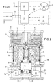
- the vacuum pump is designated 21.
- the symbol for a turbomolecular vacuum pump is shown.
- the housing 1 of the vacuum pump 21 is to be indicated by the outer dashed line.
- the power section 22 contains the electrical and electronic components for generating the current required by the drive motor of the vacuum pump 21.
- the power section 22 is supplied with voltage from the outside via the cable 24. Depending on the situation, the cable 24 connects the power section 22 to the 220 V AC network or to a 24 V industrial standard voltage supply.
- the control part 23 is connected to an operating and display device 25. This is located outside the pump housing 1 and therefore requires a connecting cable 26.
- Operating and display elements 27, 28 can also be accommodated within the pump housing 1. The elements 27, 28 can either replace the operating and display device 25 located outside the pump housing. In this solution, the cable 26 is omitted.
- Operating elements 27 and status displays 28 can, however, also be accommodated within the pump housing 1 in addition to the external operating and display device 25.
- the control part 23 can additionally be equipped with assemblies which enable monitoring of the operating parameters of the vacuum pump 21. This solution generally requires the existence of sensors in the area of the vacuum pump 21 and / or the drive motor and the connection of these sensors to the control part 23, indicated by the dash-dotted line 29. Depending on the signals supplied by the sensors, the control section 23 can be used, for example, to control the power section 22.
- FIG. 2 shows a highly schematic section through a combined turbomolecular / molecular pump.
- the housing 1 is equipped with a central, inwardly projecting bearing bush 2, in which a shaft 3 is supported by a bearing 4. Coupled to the shaft 3 are the drive motor 5, the rotor 6 of the molecular pump stage and the rotor 7 of the turbomolecular pump stage.
- the rotor 7 is equipped with the rotor blades 8 which, together with the stator blades 9 located in the housing 1, form the turbomolecular pump stage.
- the pump is connected to the recipient to be evacuated via the flange 11.
- the molecular pump stage comprises the bell-shaped rotor 6 which overlaps the storage space 12 and is equipped on its outside with thread-like grooves 13. In these grooves, gas is pumped from the high vacuum side to the fore vacuum side during operation of the pump. In addition, there is the gap 10 between the rotor 6 and the stator 14, which should be as small as possible for reasons of avoiding undesired backflow.
- the gases conveyed by the pump 21 reach the fore-vacuum chamber 19. This is followed by a connection piece 20 which is connected to a fore-vacuum pump during the operation of the vacuum pump 21.
- a removable housing section 31 is part of the housing 1 of the vacuum pump 21.
- the power section 22 and the control section 23 are located in this housing section.
- the connecting lines 24, 26 are led out of the housing section 31 via bushings 32, 33.
- Part of the removable housing section 31 is a central support 34 for the stator 35 of the electric motor.
- Temperature sensors 36 which are located in the area of the bearings 4, are shown as an example for sensors connected to the control part 23 via lines 29. This makes it possible to detect bearing damage early, which is noticeable through temperature increases.
- Dashed lines also indicate components in the pump housing 1 for operating purposes (27) and status displays (28). These blocks are - as in Figure 1 - shown in dashed lines to indicate that they do not necessarily have to be housed in the housing 1 of the vacuum pump 21.
- a supply part 37 for such magnetic bearings is also accommodated in the housing section 31 and is connected to the power part 22.
- the magnetic bearing is powered depending on position sensors (not shown).
Landscapes
- Engineering & Computer Science (AREA)
- Power Engineering (AREA)
- Mechanical Engineering (AREA)
- General Engineering & Computer Science (AREA)
- Microelectronics & Electronic Packaging (AREA)
- Non-Positive Displacement Air Blowers (AREA)
Description
- Die Erfindung bezieht sich auf eine Turbovakuumpumpe oder Molekularvakuumpumpe mit den Merkmalen des Oberbegriffs des Patentanspruchs 1.
- Eine Vakuumpumpe mit einem Wandler ist aus der EP-A-464 571 bekannt. Pumpe und Wandler sind über ein mehradriges Kabel miteinander verbunden. Über das Kabel muß zum einen die im Wandler an den Verbraucher in der Pumpe angepaßte Leistung - sei es ein hochfrequenter Wechselstrom oder eine Hochspannung - übertragen werden. Zum anderen dient das Kabel der Übertragung von Bedienungs-, Anzeige-, Steuerungs- und/oder Überwachungssignalen.
- Der Wandler mit seinem Leistungsteil und seinem Steuerteil, ggf. auch mit Bedienungs- und Anzeigeelementen, wird dort aufgestellt, wo die Bedienung der Pumpe erfolgt. Häufig liegen der Bedienungsort und der Einsatzort der Pumpe voneinander entfernt. Die Kabelverbindung zwischen dem Wandler und der Vakuumpumpe kann jedoch nicht beliebig lang sein, da sowohl die Leistungsverluste auf den Leitungen als auch Funktionsbeeinträchtigungen durch elektromagnetische Störungen mit der Leitungslänge zunehmen.
- Die US-A-44 60 317 offenbart eine Ionengetterpumpe, bei der das der Erzeugung der Hochspannung dienende Leistungsteil im Gehäuse der Pumpe untergebracht ist. Ein im Gehäuse der Ionengetterpumpe untergebrachtes Steuerteil ist nicht vorhanden. Es wird zwar die Messung eines "leakage current" beschrieben; hierbei handelt es sich jedoch um die Messung von Kriechströmen, die nach längerem Betrieb der Ionengetterpumpe im Bereich des Spaltes 46 infolge von Niederschlägen auftreten. Die Messung erfolgt in gleicher Weise und mit dem gleichen Gerät wie die Messung des Betriebsstromes; unterschiedlich ist nur, daß während der Leckstrommessung Magnete und zugehörige Joche entfernt werden.
- Der vorliegenden Erfindung liegt die Aufgabe zugrunde, die erwähnten Leistungsverluste und Funktionsbeeinträchtigungen bei einer Vakuumpumpe der eingangs erwähnten Art zu vermeiden.
- Erfindungsgemäß wird diese Aufgabe durch die kennzeichnenden Merkmale der Patentansprüche gelöst. Der Vorteil dieser Maßnahme liegt zunächst darin, daß eine lange Leitung zwischen Leistungsteil und Antriebsmotor nicht mehr erforderlich ist, selbst wenn die Bedienungs- und Anzeigeelemente weit vom Einsatzort der Pumpe entfernt liegen. Auch die Verbindungsleitungen zwischen den zu überwachenden Stellen der Vakuumpumpe und dem Steuerteil sind extrem kurz. Ein separates Gehäuse für die elektrische Versorung entfällt. Weitere Vorteile bestehen in dem geringen Volumen des Gesamtsystems und - wegen des Wegfalls von Kabeln und Steckverbindungen - in der höheren Zuverlässigkeit.
- Weitere Vorteile und Einzelheiten der Erfindung sollen an hand von in den Figuren 1 und 2 schematisch dargestellten Ausführungsbeispielen erläutert werden. Es zeigen:
- Figur 1:
- Ein Symbol-Blockschaltbild und
- Figur 2:
- einen Schnitt durch eine kombinierte Turbomolekular-/Molekularpumpe.
- Beim Ausführungsbeispiel nach Figur 1 ist die Vakuumpumpe mit 21 bezeichnet. Es ist das Symbol für eine Turbomolekularvakuumpumpe dargestellt. Durch die äußere gestrichelte Linie soll das Gehäuse 1 der Vakuumpumpe 21 angedeutet werden.
- Innerhalb des Gehäuses 1 befinden sich neben der Vakuumpumpe 21 (mit ihrem in Figur 1 nicht dargestellten Antriebsmotor) ein Leistungsteil 22 und ein Steuerteil 23. Im Leistungsteil 22 befinden sich die elektrischen und elektronischen Bauteile zur Erzeugung des vom Antriebsmotor der Vakuumpumpe 21 benötigten Stromes. Die Spannungsversorgung des Leistungsteiles 22 erfolgt von außen über das Kabel 24. Je nach der gegebenen Situation verbindet das Kabel 24 den Leistungsteil 22 mit dem 220 V-Wechselspannungsnetz oder mit einer 24 V-Industriestandardspannung-Versorgung.
- Die elektrische Versorgung des Steuerteiles 23, in dem sich zum Beispiel ein Mikorprozessor befinden kann, erfolgt ebenfalls mit Hilfe des Leistungsteiles 22. Der Steuerteil 23 steht mit einem Bedienungs- und Anzeigegerät 25 in Verbindung. Dieses befindet sich außerhalb des Pumpengehäuses 1 und benötigt deshalb ein Verbindungskabel 26. Bedienungs- und Anzeigeelemente 27, 28 können aber auch innerhalb des Pumpengehäuses 1 untergebracht sein. Die Elemente 27, 28 können entweder das außerhalb des Pumpengehäuses befindliche Bedienungs- und Anzeigegerät 25 ersetzen. Bei dieser Lösung entfällt das Kabel 26. Bedienungselemente 27 und Statusanzeigen 28 können aber auch zusätzlich zum externen Bedienungs- und Anzeigegerät 25 innerhalb des Pumpengehäuses 1 untergebracht sein.
- Der Steuerteil 23 kann zusätzlich mit Baugruppen ausgerüstet sein, die eine Überwachung von Betriebsparametern der Vakuumpumpe 21 ermöglichen. Diese Lösung setzt i.a. die Existenz von Sensoren im Bereich der Vakuumpumpe 21 und/oder des Antriebsmotors sowie die Verbindung dieser Sensoren mit dem Steuerteil 23-angedeutet durch die strichpunktierte Linie 29 - voraus. In Abhängigkeit der von den Sensoren gelieferten Signale kann mit Hilfe des Steuerteiles 23 beispielsweise der Leistungsteil 22 gesteuert werden.
- Figur 2 zeigt einen stark schematisierten Schnitt durch eine kombinierte Turbomolekular-/Molekularpumpe. Das Gehäuse 1 ist mit einer zentralen, nach innen hineinragenden Lagerbuchse 2 ausgerüstet, in der sich eine Welle 3 über eine Lagerung 4 abstützt. Mit der Welle 3 gekoppelt sind der Antriebsmotor 5, der Rotor 6 der Molekularpumpenstufe und der Rotor 7 der Turbomolekularpumpenstufe.
- Der Rotor 7 ist mit den Rotorschaufeln 8 ausgerüstet, die gemeinsam mit dem im Gehäuse 1 befindlichen Statorschaufeln 9 die Turbomolekularpumpenstufe bilden. Über den Flansch 11 wird die Pumpe an den zu evakuierenden Rezipienten angeschlossen.
- Die Molekularpumpenstufe umfaßt den den Lagerraum 12 übergreifenden, glockenförmigen Rotor 6, der auf seiner Außenseite mit gewindeähnlichen Nuten 13 ausgerüstet ist. In diesen Nuten findet während des Betriebs der Pumpe die Gasförderung von der Hochvakuumseite zur Vorvakuumseite statt. Im übrigen befindet sich zwischen dem Rotor 6 und dem Stator 14 der Spalt 10, der aus Gründen der Vermeidung einer unerwünschten Rückströmung möglichst klein sein soll. Die durch die Pumpe 21 geförderten Gase gelangen in den Vorvakuumraum 19. An diesen schließt sich ein Stutzen 20 an, der während des Betriebs der Vakuumpumpe 21 mit einer Vorvakuumpumpe in Verbindung steht.
- Bestandteil des Gehäuses 1 der Vakuumpumpe 21 ist ein abnehmbarer Gehäuseabschnitt 31. In diesem Gehäuseabschnitt befinden sich der Leistungsteil 22 und der Steuerteil 23. Über Durchführungen 32, 33 sind die Verbindungsleitungen 24, 26 aus dem Gehäuseabschnitt 31 herausgeführt.
- Bestandteil des abnehmbaren Gehäuseabschnittes 31 ist ein zentraler Träger 34 für den Stator 35 des Elektromotors. Diese Lösung ermöglicht die Trennung der elektrisch und elektronisch zu versorgenden Bauteile von der Pumpe selbst, wodurch Wartungs- und Reparaturarbeiten vereinfacht werden.
- Als Beispiel für mit dem Steuerteil 23 über Leitungen 29 in Verbindung stehende Sensoren sind Temperatursensoren 36 dargestellt, die sich im Bereich der Lager 4 befinden. Dadurch besteht die Möglichkeit, Lagerschäden, die sich durch Temperaturerhöhungen bemerkbar machen, frühzeitig festzustellen.
- Durch gestrichelte Linien angedeutet sind auch im Pumpengehäuse 1 befindliche Bauteile für Bedienungszwecke (27) und Statusanzeigen (28). Diese Blöcke sind - wie auch in Figur 1 - gestrichelt dargestellt, um anzudeuten, daß sie nicht zwingend im Gehäuse 1 der Vakuumpumpe 21 untergebracht sein müssen.
- Für den Fall, daß es sich bei der Lagerung 4 um eine aktive Magnetlagerung handelt, ist es erforderlich, diese mit Strom zu versorgen. Ein Versorgungsteil 37 für derartige Magnetlager ist ebenfalls im Gehäuseabschnitt 31 untergebracht und steht mit dem Leistungsteil 22 in Verbindung. Die Stromversorgung der Magnetlagerung erfolgt in Abhängigkeit von nicht dargestellten Positionssensoren.
Claims (7)
- Turbovakuumpumpe oder Molekularvakuumpumpe (21) mit einem Gehäuse (1), mit einem mit hoher Drehzahl betriebenen Rotor (7), mit einem Antriebsmotor (5) für den Rotor (7), mit einem Leistungsteil (22) zur elektrischen Versorgung des Antriebsmotors (5) und mit einem Steuerteil (23) zur Steuerung und/oder Überwachung der Pumpe, dadurch gekennzeichnet, daß Leistungsteil (22) und Steuerteil (23) im Gehäuse (1) der Vakuumpumpe (21) untergebracht sind.
- Pumpe nach Anspruch 1, dadurch gekennzeichnet, daß ein von der Pumpe unabhängiges Bedienungs- und Anzeigegerät (25) über eine Leitung (26) mit dem Gehäuse (1) der Vakuumpumpe (21) in Verbindung steht.
- Pumpe nach Anspruch 1, 2, dadurch gekennzeichnet, daß Bediienungselemente (27) und Statusanzeigen (28) im Gehäuse (1) der Pumpe untergebracht sind.
- Pumpe nach einem der Ansprüch 1 bis 3, dadurch gekennzeichnet, daß im Steuerteil (23) Baugruppen vorhanden sind, die eine Überwachung von Betriebsparametern der Vakuumpumpe ermöglichen, und daß zugehörige Sensoren mit dem Steuerteil (23) in Verbindung stehen.
- Pumpe nach einem der vorhergehenden Ansprüche, dadurch gekennzeichnet, daß Leistungsteil (22) und Steuerteil (23) in einem abnehmbaren Gehäuseabschnitt (31) untergebracht sind.
- Pumpe nach Anspruch 5, dadurch gekennzeichnet, daß Bestandteil des abnehmbaren Gehäuseabschnittes (31) der Stator (35) des Antriebsmotors ist.
- Pumpe nach einem der vorhergehenden Ansprüche, dadurch gekennzeichnet, daß sie einen zumindest teilweise aktiv magnetisch gelagerten Rotor umfaßt und daß die elektrische Versorgung (37) der Magnetlager zusätzlich im Pumpengehäuse (1) untergebracht ist.
Applications Claiming Priority (2)
| Application Number | Priority Date | Filing Date | Title |
|---|---|---|---|
| DE4237971A DE4237971B4 (de) | 1992-11-11 | 1992-11-11 | Vakuumpumpe mit Wandler |
| DE4237971 | 1992-11-11 |
Publications (3)
| Publication Number | Publication Date |
|---|---|
| EP0597365A1 EP0597365A1 (de) | 1994-05-18 |
| EP0597365B1 true EP0597365B1 (de) | 1997-07-23 |
| EP0597365B2 EP0597365B2 (de) | 2004-03-17 |
Family
ID=6472559
Family Applications (1)
| Application Number | Title | Priority Date | Filing Date |
|---|---|---|---|
| EP93117764A Expired - Lifetime EP0597365B2 (de) | 1992-11-11 | 1993-11-03 | Vakuumpumpe mit Wandler |
Country Status (2)
| Country | Link |
|---|---|
| EP (1) | EP0597365B2 (de) |
| DE (2) | DE4237971B4 (de) |
Cited By (1)
| Publication number | Priority date | Publication date | Assignee | Title |
|---|---|---|---|---|
| DE102006016405A1 (de) * | 2006-04-07 | 2007-10-11 | Pfeiffer Vacuum Gmbh | Vakuumpumpe mit Antriebsgerät |
Families Citing this family (12)
| Publication number | Priority date | Publication date | Assignee | Title |
|---|---|---|---|---|
| FR2747431B1 (fr) * | 1996-04-15 | 1998-07-03 | Soc D Mecanique Magnetique | Pompe turbomoleculaire a paliers magnetiques actifs |
| IT1288738B1 (it) * | 1996-10-08 | 1998-09-24 | Varian Spa | Unita' elettronica di comando per pompa da vuoto. |
| IT1288737B1 (it) * | 1996-10-08 | 1998-09-24 | Varian Spa | Dispositivo di pompaggio da vuoto. |
| DE69840607D1 (de) * | 1997-12-02 | 2009-04-09 | Ebara Corp | Magnetlagervorrichtung und turbomolekularpumpe |
| DE10215896A1 (de) * | 2002-04-11 | 2003-10-23 | Leybold Vakuum Gmbh | Vakuumpumpe |
| DE102004047853A1 (de) * | 2004-10-01 | 2006-04-20 | Festo Ag & Co. | Steuereinrichtung für wenigstens ein Saugelement |
| DE102004054004A1 (de) * | 2004-11-09 | 2006-05-11 | Pfeiffer Vacuum Gmbh | Vakuumpumpsystem und Signalerzeugungsverfahren |
| DE102005045284A1 (de) | 2005-09-22 | 2007-03-29 | Pfeiffer Vacuum Gmbh | Drehzahlüberwachungsvorrichtung |
| DE102007053980A1 (de) * | 2007-11-13 | 2009-05-14 | Pfeiffer Vacuum Gmbh | Vakuumpumpe |
| DE102008061435A1 (de) * | 2008-12-10 | 2010-06-17 | Pfeiffer Vacuum Gmbh | Mit einer Vakuumpumpe verbindbares Gerät |
| US9267392B2 (en) * | 2010-10-19 | 2016-02-23 | Edwards Japan Limited | Vacuum pump |
| DE102016209983A1 (de) | 2016-06-07 | 2017-12-07 | Leybold Gmbh | Vorrichtung und Verfahren zum Antreiben einer Vakuumpumpe |
Family Cites Families (31)
| Publication number | Priority date | Publication date | Assignee | Title |
|---|---|---|---|---|
| US3776666A (en) † | 1972-02-18 | 1973-12-04 | Deknatel Inc | Portable pump |
| CH583856A5 (de) * | 1974-09-27 | 1977-01-14 | Balzers Patent Beteilig Ag | |
| DE2457783C2 (de) * | 1974-12-06 | 1986-10-09 | Arthur Pfeiffer Vakuumtechnik Wetzlar Gmbh, 6334 Asslar | Magnetische Lagerung |
| DE2554995A1 (de) * | 1975-12-06 | 1977-06-16 | Pfeiffer Vakuumtechnik | Turbomolekularpumpe |
| DE2637497C3 (de) * | 1976-02-11 | 1979-11-29 | Viktor Yakovlevitsch Tscherny | Turbomolekular-Hochvakuumpumpe |
| US4331883A (en) * | 1979-10-29 | 1982-05-25 | Grenco S.P.A. | Portable power supply unit |
| GB2075240B (en) † | 1980-03-05 | 1985-03-13 | Papst Motoren Kg | Disc storage drive |
| US4460317A (en) * | 1981-12-14 | 1984-07-17 | Kernco, Inc. | Ion pump |
| FR2528127A1 (fr) * | 1982-06-04 | 1983-12-09 | Creusot Loire | Moto-compresseur centrifuge electrique integre a grande vitesse |
| DE3239328C2 (de) * | 1982-10-23 | 1993-12-23 | Pfeiffer Vakuumtechnik | Magnetisch gelagerte Turbomolekularpumpe mit Schwingungsdämpfung |
| JPS6034594U (ja) † | 1983-08-16 | 1985-03-09 | セイコー精機株式会社 | 縦型タ−ボ分子ポンプ |
| DE3410905A1 (de) * | 1984-03-24 | 1985-10-03 | Leybold-Heraeus GmbH, 5000 Köln | Einrichtung zur foerderung von gasen bei subatmosphaerischen druecken |
| US4832576A (en) * | 1985-05-30 | 1989-05-23 | Sanyo Electric Co., Ltd. | Electric fan |
| JPH0442559Y2 (de) † | 1985-10-03 | 1992-10-07 | ||
| FR2603667B1 (fr) † | 1986-09-10 | 1990-09-28 | Etri Sa | Ventilateur centrifuge entraine par un moteur a courant continu et a commutation electronique |
| DE3728006A1 (de) * | 1987-08-22 | 1989-03-02 | Licentia Gmbh | Geblaeseantrieb fuer die regeneriervorrichtung eines russfilters |
| US4958096A (en) † | 1987-12-21 | 1990-09-18 | Flint & Walling, Inc. | Governor and motor assembly |
| IT1219207B (it) † | 1988-04-14 | 1990-05-03 | Varian Spa | Alimentatore elettronico perfezionato per pompa ionica |
| DE3825035B4 (de) * | 1988-07-09 | 2006-11-23 | Flux-Geräte GmbH | Bürstenloser, elektrisch kommutierter Motor für eine Faß- oder eine Behälterpumpe zum Betieb an einem Wechselspannungsnetz |
| US4998865A (en) † | 1988-07-11 | 1991-03-12 | Aisan Kogyo Kabushiki Kaisha | Brushless DC pump with enclosed circuit board |
| US5004942A (en) † | 1989-02-06 | 1991-04-02 | A. O. Smith Corporation | Power and control chamber for dynamoelectric machines |
| US5073091A (en) † | 1989-09-25 | 1991-12-17 | Vickers, Incorporated | Power transmission |
| US5006743A (en) † | 1989-10-26 | 1991-04-09 | A. O. Smith Corporation | Multiple compartmented dynamoelectric machine |
| US5079464A (en) † | 1989-10-26 | 1992-01-07 | A. O. Smith Corporation | Multiply compartmented dynamoelectric machine |
| US5127148A (en) † | 1989-10-26 | 1992-07-07 | A. O. Smith Corporation | Method of fabricating a dynameoelectric machine |
| FR2663690B1 (fr) * | 1990-06-26 | 1994-04-01 | Alcatel Cit | Dispositif permettant d'assurer une gestion sure d'une pompe a vide. |
| SU1751499A1 (ru) * | 1990-08-13 | 1992-07-30 | Институт ядерной энергетики АН БССР | Способ управлени радиальными активными магнитными подшипниками роторной машины и роторна машина |
| US5092748A (en) † | 1990-09-06 | 1992-03-03 | Ketema Aerospace & Electronics Division | Fuel metering pump system |
| US5096390A (en) † | 1990-10-16 | 1992-03-17 | Micropump Corporation | Pump assembly with integral electronically commutated drive system |
| US5156535A (en) † | 1990-10-31 | 1992-10-20 | Itt Corporation | High speed whirlpool pump |
| US5120201A (en) † | 1990-12-17 | 1992-06-09 | Walbro Corporation | Brushless DC fuel pump responsive to pressure sensor |
-
1992
- 1992-11-11 DE DE4237971A patent/DE4237971B4/de not_active Expired - Fee Related
-
1993
- 1993-11-03 DE DE59306966T patent/DE59306966D1/de not_active Expired - Lifetime
- 1993-11-03 EP EP93117764A patent/EP0597365B2/de not_active Expired - Lifetime
Cited By (2)
| Publication number | Priority date | Publication date | Assignee | Title |
|---|---|---|---|---|
| DE102006016405A1 (de) * | 2006-04-07 | 2007-10-11 | Pfeiffer Vacuum Gmbh | Vakuumpumpe mit Antriebsgerät |
| DE102006016405B4 (de) | 2006-04-07 | 2024-08-01 | Pfeiffer Vacuum Gmbh | Vakuumpumpe mit Antriebsgerät |
Also Published As
| Publication number | Publication date |
|---|---|
| DE4237971B4 (de) | 2004-05-06 |
| DE4237971A1 (de) | 1994-05-19 |
| DE59306966D1 (de) | 1997-08-28 |
| EP0597365A1 (de) | 1994-05-18 |
| EP0597365B2 (de) | 2004-03-17 |
Similar Documents
| Publication | Publication Date | Title |
|---|---|---|
| EP0597365B2 (de) | Vakuumpumpe mit Wandler | |
| DE3208133A1 (de) | Elektromagnetisches lager mit redundanzeigenschaften | |
| EP3378152B1 (de) | Elektrischer antrieb für einen industriellen roboter | |
| DE2248594B2 (de) | Transportables Kühlaggregat | |
| EP1093207A2 (de) | Elektromotor | |
| EP3513491A1 (de) | Verfahren zur inbetriebnahme einer permanenterregte synchronmaschine und permanenterregte synchronmaschine | |
| EP0139869B1 (de) | Regelsystem für einen polumschaltbaren elektrischen Motor | |
| WO1998059407A1 (de) | Magnetgelagerter elektrischer antrieb | |
| DE102011055137A1 (de) | Hybrid-Synchronmaschine | |
| EP2866343B1 (de) | Vakuumpumpe | |
| DE2530112A1 (de) | Schaltungsanordnung zum automatischen entregen eines motors | |
| CN113189486A (zh) | 一种快速检测三相异步电机转向的方法 | |
| EP3318764B1 (de) | Vakuumpumpe mit überdrehzahlsicherung | |
| US20210305867A1 (en) | Stator winding system with serial coil winding | |
| CN111645708B (zh) | 转换开关控制装置、转换开关及轨道车辆 | |
| EP2616266A1 (de) | Kraftwagen mit einer hochspannungsquelle | |
| WO2016135336A1 (de) | Gleichstrommotor/generator mit integrierter leistungsregelung sowie eine steuerschaltung für einen gleichstrommotor | |
| DE102005045284A1 (de) | Drehzahlüberwachungsvorrichtung | |
| DE4426309A1 (de) | Drehzahlgeregelter mehrpolpaariger Gleichstrommotor | |
| DE102006057213A1 (de) | Elektrische Antriebsvorrichtung | |
| EP2667496A2 (de) | Einen elektrischen Pumpenmotor aufweisendes Flurförderzeug | |
| EP2700135B1 (de) | Schaltungsanordnung für ein wechselstromschütz, motorschutzrelais und verfahren zur herstellung einer spannungsversorgung | |
| WO2016050459A1 (de) | Rotor, synchronmaschine und hybridantrieb | |
| CN113934134B (zh) | 一种松乱绳安全控制电路及系统 | |
| EP4376289A1 (de) | Antriebseinheit für einen lüfter mit einer drehzahlcodierung basierend auf einer selektiven energieübertragung über zwei getrennte elektrische anschlussleitungssysteme |
Legal Events
| Date | Code | Title | Description |
|---|---|---|---|
| PUAI | Public reference made under article 153(3) epc to a published international application that has entered the european phase |
Free format text: ORIGINAL CODE: 0009012 |
|
| AK | Designated contracting states |
Kind code of ref document: A1 Designated state(s): CH DE FR GB LI |
|
| 17P | Request for examination filed |
Effective date: 19941111 |
|
| 17Q | First examination report despatched |
Effective date: 19950120 |
|
| RAP1 | Party data changed (applicant data changed or rights of an application transferred) |
Owner name: BALZERS UND LEYBOLD DEUTSCHLAND HOLDING AKTIENGESE |
|
| GRAG | Despatch of communication of intention to grant |
Free format text: ORIGINAL CODE: EPIDOS AGRA |
|
| GRAH | Despatch of communication of intention to grant a patent |
Free format text: ORIGINAL CODE: EPIDOS IGRA |
|
| GRAH | Despatch of communication of intention to grant a patent |
Free format text: ORIGINAL CODE: EPIDOS IGRA |
|
| GRAA | (expected) grant |
Free format text: ORIGINAL CODE: 0009210 |
|
| AK | Designated contracting states |
Kind code of ref document: B1 Designated state(s): CH DE FR GB LI |
|
| REG | Reference to a national code |
Ref country code: CH Ref legal event code: EP |
|
| REF | Corresponds to: |
Ref document number: 59306966 Country of ref document: DE Date of ref document: 19970828 |
|
| REG | Reference to a national code |
Ref country code: CH Ref legal event code: NV Representative=s name: ISLER & PEDRAZZINI AG |
|
| GBT | Gb: translation of ep patent filed (gb section 77(6)(a)/1977) |
Effective date: 19970911 |
|
| PGFP | Annual fee paid to national office [announced via postgrant information from national office to epo] |
Ref country code: CH Payment date: 19971028 Year of fee payment: 5 |
|
| ET | Fr: translation filed | ||
| PLBQ | Unpublished change to opponent data |
Free format text: ORIGINAL CODE: EPIDOS OPPO |
|
| PLBI | Opposition filed |
Free format text: ORIGINAL CODE: 0009260 |
|
| PLBF | Reply of patent proprietor to notice(s) of opposition |
Free format text: ORIGINAL CODE: EPIDOS OBSO |
|
| 26 | Opposition filed |
Opponent name: VARIAN ASSOCIATES, INC. Effective date: 19980422 Opponent name: THE BOC GROUP PLC Effective date: 19980422 Opponent name: PFEIFFER VACUUM GMBH Effective date: 19980414 |
|
| PLBF | Reply of patent proprietor to notice(s) of opposition |
Free format text: ORIGINAL CODE: EPIDOS OBSO |
|
| PG25 | Lapsed in a contracting state [announced via postgrant information from national office to epo] |
Ref country code: LI Free format text: LAPSE BECAUSE OF NON-PAYMENT OF DUE FEES Effective date: 19981130 Ref country code: CH Free format text: LAPSE BECAUSE OF NON-PAYMENT OF DUE FEES Effective date: 19981130 |
|
| PLBF | Reply of patent proprietor to notice(s) of opposition |
Free format text: ORIGINAL CODE: EPIDOS OBSO |
|
| REG | Reference to a national code |
Ref country code: CH Ref legal event code: PL |
|
| RDAH | Patent revoked |
Free format text: ORIGINAL CODE: EPIDOS REVO |
|
| APAC | Appeal dossier modified |
Free format text: ORIGINAL CODE: EPIDOS NOAPO |
|
| APAE | Appeal reference modified |
Free format text: ORIGINAL CODE: EPIDOS REFNO |
|
| APAC | Appeal dossier modified |
Free format text: ORIGINAL CODE: EPIDOS NOAPO |
|
| REG | Reference to a national code |
Ref country code: GB Ref legal event code: IF02 |
|
| PLAB | Opposition data, opponent's data or that of the opponent's representative modified |
Free format text: ORIGINAL CODE: 0009299OPPO |
|
| PLBQ | Unpublished change to opponent data |
Free format text: ORIGINAL CODE: EPIDOS OPPO |
|
| R26 | Opposition filed (corrected) |
Opponent name: PFEIFFER VACUUM GMBH * 19980422 THE BOC GROUP PLC Effective date: 19980414 |
|
| PLAB | Opposition data, opponent's data or that of the opponent's representative modified |
Free format text: ORIGINAL CODE: 0009299OPPO |
|
| PLBQ | Unpublished change to opponent data |
Free format text: ORIGINAL CODE: EPIDOS OPPO |
|
| PLAB | Opposition data, opponent's data or that of the opponent's representative modified |
Free format text: ORIGINAL CODE: 0009299OPPO |
|
| APBU | Appeal procedure closed |
Free format text: ORIGINAL CODE: EPIDOSNNOA9O |
|
| R26 | Opposition filed (corrected) |
Opponent name: VARIAN ASSOCIATES, INC. Effective date: 19980422 Opponent name: THE BOC GROUP PLC Effective date: 19980422 Opponent name: PFEIFFER VACUUM GMBH Effective date: 19980414 |
|
| R26 | Opposition filed (corrected) |
Opponent name: VARIAN INC. Effective date: 19980422 Opponent name: THE BOC GROUP PLC Effective date: 19980422 Opponent name: PFEIFFER VACUUM GMBH Effective date: 19980414 |
|
| PUAH | Patent maintained in amended form |
Free format text: ORIGINAL CODE: 0009272 |
|
| STAA | Information on the status of an ep patent application or granted ep patent |
Free format text: STATUS: PATENT MAINTAINED AS AMENDED |
|
| 27A | Patent maintained in amended form |
Effective date: 20040317 |
|
| AK | Designated contracting states |
Kind code of ref document: B2 Designated state(s): CH DE FR GB LI |
|
| GBTA | Gb: translation of amended ep patent filed (gb section 77(6)(b)/1977) | ||
| ET3 | Fr: translation filed ** decision concerning opposition | ||
| APAH | Appeal reference modified |
Free format text: ORIGINAL CODE: EPIDOSCREFNO |
|
| PGFP | Annual fee paid to national office [announced via postgrant information from national office to epo] |
Ref country code: DE Payment date: 20091120 Year of fee payment: 17 |
|
| PGFP | Annual fee paid to national office [announced via postgrant information from national office to epo] |
Ref country code: GB Payment date: 20091119 Year of fee payment: 17 Ref country code: FR Payment date: 20091201 Year of fee payment: 17 |
|
| GBPC | Gb: european patent ceased through non-payment of renewal fee |
Effective date: 20101103 |
|
| REG | Reference to a national code |
Ref country code: FR Ref legal event code: ST Effective date: 20110801 |
|
| REG | Reference to a national code |
Ref country code: DE Ref legal event code: R119 Ref document number: 59306966 Country of ref document: DE Effective date: 20110601 Ref country code: DE Ref legal event code: R119 Ref document number: 59306966 Country of ref document: DE Effective date: 20110531 |
|
| PG25 | Lapsed in a contracting state [announced via postgrant information from national office to epo] |
Ref country code: DE Free format text: LAPSE BECAUSE OF NON-PAYMENT OF DUE FEES Effective date: 20110531 |
|
| PG25 | Lapsed in a contracting state [announced via postgrant information from national office to epo] |
Ref country code: FR Free format text: LAPSE BECAUSE OF NON-PAYMENT OF DUE FEES Effective date: 20101130 |
|
| PG25 | Lapsed in a contracting state [announced via postgrant information from national office to epo] |
Ref country code: GB Free format text: LAPSE BECAUSE OF NON-PAYMENT OF DUE FEES Effective date: 20101103 |