EP0596771B1 - Device for electric connection of printed circuit boards at least one of which is flexible - Google Patents
Device for electric connection of printed circuit boards at least one of which is flexible Download PDFInfo
- Publication number
- EP0596771B1 EP0596771B1 EP93402616A EP93402616A EP0596771B1 EP 0596771 B1 EP0596771 B1 EP 0596771B1 EP 93402616 A EP93402616 A EP 93402616A EP 93402616 A EP93402616 A EP 93402616A EP 0596771 B1 EP0596771 B1 EP 0596771B1
- Authority
- EP
- European Patent Office
- Prior art keywords
- supports
- electrical connection
- contacts
- housing
- connection device
- Prior art date
- Legal status (The legal status is an assumption and is not a legal conclusion. Google has not performed a legal analysis and makes no representation as to the accuracy of the status listed.)
- Expired - Lifetime
Links
- 239000000463 material Substances 0.000 claims abstract description 17
- 230000000295 complement effect Effects 0.000 claims description 3
- 229920001971 elastomer Polymers 0.000 claims description 3
- 239000000806 elastomer Substances 0.000 claims description 3
- 238000003780 insertion Methods 0.000 description 3
- 230000037431 insertion Effects 0.000 description 3
- 241001314298 Verbascum sinuatum Species 0.000 description 1
- 230000003247 decreasing effect Effects 0.000 description 1
- 238000009434 installation Methods 0.000 description 1
- 238000012423 maintenance Methods 0.000 description 1
- 239000002184 metal Substances 0.000 description 1
Images

Classifications
-
- H—ELECTRICITY
- H01—ELECTRIC ELEMENTS
- H01R—ELECTRICALLY-CONDUCTIVE CONNECTIONS; STRUCTURAL ASSOCIATIONS OF A PLURALITY OF MUTUALLY-INSULATED ELECTRICAL CONNECTING ELEMENTS; COUPLING DEVICES; CURRENT COLLECTORS
- H01R13/00—Details of coupling devices of the kinds covered by groups H01R12/70 or H01R24/00 - H01R33/00
- H01R13/02—Contact members
- H01R13/22—Contacts for co-operating by abutting
- H01R13/24—Contacts for co-operating by abutting resilient; resiliently-mounted
- H01R13/2464—Contacts for co-operating by abutting resilient; resiliently-mounted characterized by the contact point
- H01R13/2471—Contacts for co-operating by abutting resilient; resiliently-mounted characterized by the contact point pin shaped
-
- H—ELECTRICITY
- H01—ELECTRIC ELEMENTS
- H01R—ELECTRICALLY-CONDUCTIVE CONNECTIONS; STRUCTURAL ASSOCIATIONS OF A PLURALITY OF MUTUALLY-INSULATED ELECTRICAL CONNECTING ELEMENTS; COUPLING DEVICES; CURRENT COLLECTORS
- H01R12/00—Structural associations of a plurality of mutually-insulated electrical connecting elements, specially adapted for printed circuits, e.g. printed circuit boards [PCB], flat or ribbon cables, or like generally planar structures, e.g. terminal strips, terminal blocks; Coupling devices specially adapted for printed circuits, flat or ribbon cables, or like generally planar structures; Terminals specially adapted for contact with, or insertion into, printed circuits, flat or ribbon cables, or like generally planar structures
- H01R12/70—Coupling devices
- H01R12/77—Coupling devices for flexible printed circuits, flat or ribbon cables or like structures
- H01R12/78—Coupling devices for flexible printed circuits, flat or ribbon cables or like structures connecting to other flexible printed circuits, flat or ribbon cables or like structures
-
- H—ELECTRICITY
- H01—ELECTRIC ELEMENTS
- H01R—ELECTRICALLY-CONDUCTIVE CONNECTIONS; STRUCTURAL ASSOCIATIONS OF A PLURALITY OF MUTUALLY-INSULATED ELECTRICAL CONNECTING ELEMENTS; COUPLING DEVICES; CURRENT COLLECTORS
- H01R12/00—Structural associations of a plurality of mutually-insulated electrical connecting elements, specially adapted for printed circuits, e.g. printed circuit boards [PCB], flat or ribbon cables, or like generally planar structures, e.g. terminal strips, terminal blocks; Coupling devices specially adapted for printed circuits, flat or ribbon cables, or like generally planar structures; Terminals specially adapted for contact with, or insertion into, printed circuits, flat or ribbon cables, or like generally planar structures
- H01R12/70—Coupling devices
- H01R12/77—Coupling devices for flexible printed circuits, flat or ribbon cables or like structures
- H01R12/79—Coupling devices for flexible printed circuits, flat or ribbon cables or like structures connecting to rigid printed circuits or like structures
-
- H—ELECTRICITY
- H05—ELECTRIC TECHNIQUES NOT OTHERWISE PROVIDED FOR
- H05K—PRINTED CIRCUITS; CASINGS OR CONSTRUCTIONAL DETAILS OF ELECTRIC APPARATUS; MANUFACTURE OF ASSEMBLAGES OF ELECTRICAL COMPONENTS
- H05K3/00—Apparatus or processes for manufacturing printed circuits
- H05K3/36—Assembling printed circuits with other printed circuits
- H05K3/361—Assembling flexible printed circuits with other printed circuits
- H05K3/365—Assembling flexible printed circuits with other printed circuits by abutting, i.e. without alloying process
Definitions
- the present invention relates to electrical connection devices for insulating supports, carrying printed circuits, at least one of which is flexible.
- connectors are used provided with female plugs, into which are plugged male plugs arranged on said supports.
- female plugs into which are plugged male plugs arranged on said supports.
- the contacting being done by force, there is a wear of the plugs decreasing the efficiency of the connection after a certain number of plugging and unplugging operations.
- the replacement of said plugs is delicate and very expensive, and the same is true for the implementation of a surface protection against wear, such as for example the covering of the plugs with a metal resistant to 'wear.
- the object of the present invention is to remedy these drawbacks and relates to a connection device which does not involve any insertion friction, when the supports, carrying printed circuits, are brought into electrical contact.
- the connection device according to the present invention is specially adapted for a connection, for which at least one of the supports is flexible.
- connection device intended for connecting insulating supports, carrying printed circuits, at least one of which is flexible, each of said supports being provided on one of its faces with contacts intended for connection, is remarkable.
- said contacts protrude relative to the face of said supports which carries them and in that said connection device electric comprises a layer of elastically deformable material, capable of exerting pressure on the face not provided with contacts of said flexible support, in order to press it against at least one other of said supports, which is in abutment against a rigid element, so that each contact, intended to be connected, of said flexible support is brought into contact with a contact, intended to be connected, of another of said supports.
- the present invention therefore eliminates the problems due to insertion friction, by creating a connection device in which the electrical connection does not result from the insertion of an element into another element, but from the simple contacting of two elements, in this case the contacting of two contacts arranged on the faces of the supports to be connected.
- the supports to be connected are arranged opposite one another so that each contact, intended for connection, of one of said supports, is facing a contact, intended for connection, of another of said supports.
- the electrical connection device then allows, thanks to said layer of material elastically deformable, to exert pressure on the face not provided with contacts of the flexible support, opposite the contact which is less protruding, such that said flexible support deforms locally in order to fill said spacing and ensure contacting of said less protruding contact with his associated contact.
- the pressure applied is thus distributed along the flexible support so as to obtain an adequate pressure at the level of each contact to allow the electrical connection of all the protruding contacts, intended for connection, by compensating for any height inequalities of said contacts.
- variable spacing between the ends of associated contacts could also be due to a lack of flatness of the surface provided with contacts of one of said supports.
- said electrical connection device comprises a pressure plate which carries said layer of elastically deformable material by its face which is not in contact with the flexible support and which is, for example, subjected to the pressure of a spring, which provides the contact pressure.
- said electrical connection device comprises, on the one hand, a housing containing said pressure plate and said spring and releasing said layer of elastically deformable material, and, on the other hand, a rigid cover which can be coupled to said housing opposite said layer of elastically deformable material.
- said electrical connection device may be provided with complementary guiding means, for example positioning pins arranged on said housing and recesses made in said cover, guiding the movements of approaching and moving said cover away from said housing.
- Said positioning pins can, moreover, be intended to favor the positioning of the supports on the housing, said supports having holes and being placed by means of the latter on said positioning pins.
- said housing and said rigid cover can also be provided with a screw fixing system facilitating the installation and maintenance of said connection device.
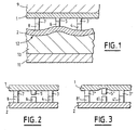
- Figure 1 is an enlarged schematic sectional view illustrating the electrical connection between a flexible support and a rigid support, according to the invention.
- Figure 2 shows partially in section two supports provided with contacts arranged opposite one another.
- FIG. 3 also shows in partial section two supports arranged opposite one another, one of which has a surface recess.
- FIG. 4 is a cross-sectional view of an embodiment of the present invention, along the line IV-IV of FIG. 5.
- Figure 5 is a sectional view along the line V-V in Figure 4.
- the electrical connection device in accordance with the present invention and shown diagrammatically and partially in FIG. 1, is intended to electrically connect insulating supports 1 and 2, carrying printed circuits, and provided with contacts 3, 4, 5, 6, 7 and 8 which project from the surface of said supports. Said contacts have the same arrangement on each of said supports 1 and 2, so that each contact 3, 5, 7 of support 1 can be brought opposite a contact 4, 6, 8 of support 2, when the two supports are arranged one opposite the other.
- the support 1 is supported on a rigid element 9.
- the support 2 is pressed against said support 1 by a layer 10 of elastically deformable material, for example an elastomer, subjected to the pressure of a pressure plate 11.
- Said pressed support 2 is flexible, while the other support 1, which bears on the rigid element 9 and which does not therefore undergo any deformation, even if it is flexible, can be either flexible or rigid.
- the contact 5 is less protruding than the neighboring contacts 3 and 7.
- the contacts 3 and 7 respectively come into contact contacts 4 and 8 associated with them, while contact 5 is not protruding enough to reach contact 6 associated with it.
- the distance separating two contacts is even greater when each of the two associated contacts is less prominent than its neighbors.
- the contacting of the contacts 5 and 6 is obtained by deformation of the flexible support 2 under the action of the layer 10 of elastically deformable material.
- Said flexible support 2 reproduces, in fact, the shape of the pressure surface 12 of said layer 10. The latter, when pressed against the flexible support 2, acquires, thanks to its elasticity, a thickness which varies according to the location of the contacts of the flexible support which are supported on their associated contacts.
- the pressure surface 12 and the flexible support 2 have a configuration such that all the contacts of the flexible support 2 bear against the contacts of the support 1 which are associated with them.
- the undesirable spacing between two associated contacts, in the close contact position of said supports 1 and 2 can come, either as shown in FIG. 2 and mentioned above, from a lower height of at least one of the contacts, either as shown in Figure 3, a lack of flatness of the surface of the support 1 provided with contacts, a contact 5 'then being in a recess of said surface.
- the contacts 3 ', 4', 5 ', 6', 7 'and 8' arranged on the supports 1 and 2 play the same role as the contacts 3, 4, 5, 6, 7 and 8 of Figure 2.
- the electrical connection device comprises a housing 22 and a rigid cover 9, which is capable of being fixed on said housing 22 using screws 23.
- Said electrical connection device also comprises a wavy leaf spring 24 housed in the housing 22, bearing against the bottom of the latter and pushing outward a pressure plate 11.
- Said pressure plate 11 is pushed by the spring 24 against stops 25 and 26, which are arranged on said housing 22, and which make it trapped in the housing 22.
- said pressure plate 11 is covered with a layer 10 of elastically deformable material which protrudes at the outside of the housing, between the stops 25 and 26.
- Said electrical connection device is intended to connect two supports 1 and 2 both provided, on one face of one of their ends, with protruding contacts such as those bearing the references 3 to 8 and 3 'to 8' of the figures 1 to 3.
- the ends provided with contacts of said supports 1 and 2 are arranged, face to face, on said housing 22, the support 2 which bears on the housing 22 and on the layer 10 of elastically deformable material being flexible, the other support 1 can be either rigid or flexible.
- Said supports 1 and 2 are placed on said housing 22 by means of projecting positioning pins 27 arranged on the pressure plate 11 and intended to be placed in holes 29 and 30, respectively provided on said supports 1 and 2
- the supports 1 and 2 are then in the same situation as in FIG. 1. They are, in fact, compressed between the rigid cover 9 and the layer 10 of elastically deformable material.
- the rigid cover 9 is screwed on, until the pressure exerted by said layer 10, under the action of the spring 24 and of the pressure plate 11, is sufficient to allow electrical connection between all of the associated pairs of contacts of the two supports 1 and 2.
Landscapes
- Engineering & Computer Science (AREA)
- Metallurgy (AREA)
- Manufacturing & Machinery (AREA)
- Microelectronics & Electronic Packaging (AREA)
- Coupling Device And Connection With Printed Circuit (AREA)
- Multi-Conductor Connections (AREA)
- Combinations Of Printed Boards (AREA)
Abstract
Description
La présente invention concerne les dispositifs de connexion électrique pour des supports isolants, porteurs de circuits imprimés, dont au moins l'un est souple.The present invention relates to electrical connection devices for insulating supports, carrying printed circuits, at least one of which is flexible.
On sait que, généralement, pour la connexion de tels supports, on utilise des connecteurs munis de fiches femelles, dans lesquelles viennent s'enficher des fiches mâles agencées sur lesdits supports. Pour réaliser un bon contact, il est nécessaire d'établir une pression de contact élevée entre la fiche mâle et la fiche femelle de chaque couple de contacts. La mise en contact se faisant à force, il se produit une usure des fiches diminuant l'efficacité de la connexion après un certain nombre de manoeuvres d'enfichage et de désenfichage. Lorsqu'il est possible, le remplacement desdites fiches est délicat et fort coûteux, et il en est de même de la mise en oeuvre d'une protection superficielle contre l'usure, comme par exemple le recouvrement des fiches par un métal résistant à l'usure.It is known that, generally, for the connection of such supports, connectors are used provided with female plugs, into which are plugged male plugs arranged on said supports. To achieve good contact, it is necessary to establish a high contact pressure between the male plug and the female plug of each pair of contacts. The contacting being done by force, there is a wear of the plugs decreasing the efficiency of the connection after a certain number of plugging and unplugging operations. When it is possible, the replacement of said plugs is delicate and very expensive, and the same is true for the implementation of a surface protection against wear, such as for example the covering of the plugs with a metal resistant to 'wear.
La présente invention a pour but de remédier à ces inconvénients et concerne un dispositif de connexion ne mettant en jeu aucun frottement d'insertion, lors de la mise en contact électrique des supports, porteurs de circuits imprimés. Le dispositif de connexion conforme à la présente invention est spécialement adapté à une connexion, pour laquelle au moins l'un des supports est souple.The object of the present invention is to remedy these drawbacks and relates to a connection device which does not involve any insertion friction, when the supports, carrying printed circuits, are brought into electrical contact. The connection device according to the present invention is specially adapted for a connection, for which at least one of the supports is flexible.
Le dispositif de connexion électrique selon l'invention, destiné à connecter des supports isolants, porteurs de circuits imprimés, dont au moins l'un est souple, chacun desdits supports étant muni sur une de ses faces de contacts destinés à la connexion, est remarquable en ce que lesdits contacts font saillie par rapport à la face desdits supports qui les porte et en ce que ledit dispositif de connexion électrique comporte une couche de matière élastiquement déformable, susceptible d'exercer une pression sur la face non pourvue de contacts dudit support souple, afin de le presser contre au moins un autre desdits supports, qui est en appui contre un élément rigide, de sorte que chaque contact, destiné à être connecté, dudit support souple est mis en contact avec un contact, destiné à être connecté, d'un autre desdits supports.The electrical connection device according to the invention, intended for connecting insulating supports, carrying printed circuits, at least one of which is flexible, each of said supports being provided on one of its faces with contacts intended for connection, is remarkable. in that said contacts protrude relative to the face of said supports which carries them and in that said connection device electric comprises a layer of elastically deformable material, capable of exerting pressure on the face not provided with contacts of said flexible support, in order to press it against at least one other of said supports, which is in abutment against a rigid element, so that each contact, intended to be connected, of said flexible support is brought into contact with a contact, intended to be connected, of another of said supports.
La présente invention élimine donc les problèmes dus aux frottements d'insertion, en créant un dispositif de connexion dans lequel la connexion électrique ne résulte pas de l'insertion d'un élément dans un autre élément, mais de la simple mise en contact de deux éléments, en l'occurrence la mise en contact de deux contacts agencés sur les faces des supports à connecter.The present invention therefore eliminates the problems due to insertion friction, by creating a connection device in which the electrical connection does not result from the insertion of an element into another element, but from the simple contacting of two elements, in this case the contacting of two contacts arranged on the faces of the supports to be connected.
Les supports à connecter sont disposés les uns en regard des autres de sorte que chaque contact, destiné à la connexion, d'un desdits supports, se trouve face à un contact, destiné à la connexion, d'un autre desdits supports.The supports to be connected are arranged opposite one another so that each contact, intended for connection, of one of said supports, is facing a contact, intended for connection, of another of said supports.
On remarquera, toutefois, que le simple fait de presser, dans une telle position, l'un desdits supports contre un autre desdits supports qui lui fait face, ne garantirait pas la mise en contact de toutes les paires de contacts associés. Il se pourrait, en effet, qu'un contact protubérant soit moins saillant que les contacts qui lui sont voisins, et qu'en exerçant une pression uniforme, lesdits contacts voisins arrivent au contact des contacts qui leurs sont associés, tandis que ledit contact moins saillant n'atteigne pas le contact qui lui est associé, ménageant un espacement avec celui-ci.It will be noted, however, that the simple fact of pressing, in such a position, one of said supports against another of said supports which faces it, would not guarantee the bringing into contact of all the pairs of associated contacts. It could be, in fact, that a protruding contact is less salient than the contacts which are close to it, and that by exerting a uniform pressure, said neighboring contacts come into contact with the contacts which are associated with them, while said contact less protruding does not reach the contact associated therewith, providing space therewith.
Selon l'invention, le dispositif de connexion électrique permet alors, grâce à ladite couche de matière élastiquement déformable, d'exercer une pression sur la face non pourvue de contacts du support souple, en face du contact qui est moins saillant, telle que ledit support souple se déforme localement afin de combler ledit espacement et assurer la mise en contact dudit contact moins saillant avec son contact associé.According to the invention, the electrical connection device then allows, thanks to said layer of material elastically deformable, to exert pressure on the face not provided with contacts of the flexible support, opposite the contact which is less protruding, such that said flexible support deforms locally in order to fill said spacing and ensure contacting of said less protruding contact with his associated contact.
La pression appliquée est ainsi répartie le long du support souple de manière à obtenir une pression adéquate au niveau de chaque contact pour permettre la connexion électrique de tous les contacts protubérants, destinés à la connexion, en compensant les inégalités de hauteur éventuelles desdits contacts.The pressure applied is thus distributed along the flexible support so as to obtain an adequate pressure at the level of each contact to allow the electrical connection of all the protruding contacts, intended for connection, by compensating for any height inequalities of said contacts.
Cette répartition de la pression est obtenue grâce à l'élasticité de ladite couche de matière élastiquement déformable, par exemple un élastomère, pressée contre ledit support souple. En effet, suivant les points de contact, l'épaisseur de ladite couche varie, entraînant une déformation de sa surface qui est pressée contre le support souple. Ce dernier reproduit la même déformation, permettant alors de remédier aux différences entre les espacements séparant les différents contacts associés.This pressure distribution is obtained thanks to the elasticity of said layer of elastically deformable material, for example an elastomer, pressed against said flexible support. Indeed, according to the contact points, the thickness of said layer varies, causing a deformation of its surface which is pressed against the flexible support. The latter reproduces the same deformation, thus making it possible to remedy the differences between the spacings separating the various associated contacts.
Il est à noter qu'un espacement variable entre les extrémités de contacts associés, tel que mentionné ci-dessus, pourrait également être dû à un manque de planéité de la surface pourvue de contacts d'un desdits supports. Un contact qui se trouverait, par exemple, dans un creux de la surface, bien qu'étant de même longueur que ses contacts voisins, présenterait une extrémité qui serait en retrait par rapport aux extrémités desdits contacts voisins.It should be noted that a variable spacing between the ends of associated contacts, as mentioned above, could also be due to a lack of flatness of the surface provided with contacts of one of said supports. A contact which would be, for example, in a hollow in the surface, although being the same length as its neighboring contacts, would have an end which would be set back relative to the ends of said neighboring contacts.
De façon avantageuse, ledit dispositif de connexion électrique comporte une plaque de pression qui porte ladite couche de matière élastiquement déformable par sa face qui n'est pas en contact avec le support souple et qui est, par exemple, soumise à la pression d'un ressort, qui assure la pression de contact.Advantageously, said electrical connection device comprises a pressure plate which carries said layer of elastically deformable material by its face which is not in contact with the flexible support and which is, for example, subjected to the pressure of a spring, which provides the contact pressure.
Selon un mode de réalisation avantageux, ledit dispositif de connexion électrique comporte, d'une part, un boîtier contenant ladite plaque de pression et ledit ressort et dégageant ladite couche de matière élastiquement déformable, et, d'autre part, un couvercle rigide pouvant être accouplé audit boîtier en regard de ladite couche de matière élastiquement déformable.According to an advantageous embodiment, said electrical connection device comprises, on the one hand, a housing containing said pressure plate and said spring and releasing said layer of elastically deformable material, and, on the other hand, a rigid cover which can be coupled to said housing opposite said layer of elastically deformable material.
Par ailleurs, ledit dispositif de connexion électrique peut être muni de moyens de guidage complémentaires, par exemple des pions de positionnement agencés sur ledit boîtier et des évidements pratiqués dans ledit couvercle, guidant les mouvements de rapprochement et d'éloignement dudit couvercle par rapport audit boîtier. Lesdits pions de positionnement peuvent, en outre, être destinés à favoriser le positionnement des supports sur le boîtier, lesdits supports présentant des trous et venant se placer par l'intermédiaire de ces derniers sur lesdits pions de positionnement.Furthermore, said electrical connection device may be provided with complementary guiding means, for example positioning pins arranged on said housing and recesses made in said cover, guiding the movements of approaching and moving said cover away from said housing. . Said positioning pins can, moreover, be intended to favor the positioning of the supports on the housing, said supports having holes and being placed by means of the latter on said positioning pins.
Avantageusement, ledit boîtier et ledit couvercle rigide peuvent également être munis d'un système de fixation par vis facilitant la mise en place et la maintenance dudit dispositif de connexion.Advantageously, said housing and said rigid cover can also be provided with a screw fixing system facilitating the installation and maintenance of said connection device.
Les figures du dessin annexé feront bien comprendre comment l'invention peut être réalisée. Sur ces figures, des références identiques désignent des éléments semblables.The figures of the appended drawing will make it clear how the invention can be implemented. In these figures, identical references designate similar elements.
La figure 1 est une vue en coupe schématique agrandie illustrant la connexion électrique entre un support souple et un support rigide, conformément à l'invention.Figure 1 is an enlarged schematic sectional view illustrating the electrical connection between a flexible support and a rigid support, according to the invention.
La figure 2 montre partiellement en coupe deux supports munis de contacts disposés en regard l'un de l'autre.Figure 2 shows partially in section two supports provided with contacts arranged opposite one another.
La figure 3 montre également en coupe partielle deux supports disposés en regard l'un de l'autre, dont l'un présente un creux de surface.FIG. 3 also shows in partial section two supports arranged opposite one another, one of which has a surface recess.
La figure 4 est une vue en coupe transversale d'un mode de réalisation de la présente invention, selon la ligne IV-IV de la figure 5.FIG. 4 is a cross-sectional view of an embodiment of the present invention, along the line IV-IV of FIG. 5.
La figure 5 est une vue en coupe, selon la ligne V-V de la figure 4.Figure 5 is a sectional view along the line V-V in Figure 4.
Le dispositif de connexion électrique, conforme à la présente invention et représenté schématiquement et partiellement sur la figure 1, est destiné à connecter électriquement des supports isolants 1 et 2, porteurs de circuits imprimés, et munis de contacts 3, 4, 5, 6, 7 et 8 qui font saillie par rapport à la surface desdits supports. Lesdits contacts présentent un même agencement sur chacun desdits supports 1 et 2, de sorte que chaque contact 3, 5, 7 du support 1 peut être amené en regard d'un contact 4, 6, 8 du support 2, lorsque les deux supports sont disposés l'un en regard de l'autre.The electrical connection device, in accordance with the present invention and shown diagrammatically and partially in FIG. 1, is intended to electrically connect
Le support 1 prend appui sur un élément rigide 9. Le support 2 est pressé contre ledit support 1 par une couche 10 de matière élastiquement déformable, par exemple un élastomère, soumise à la pression d'une plaque de pression 11. Ledit support pressé 2 est souple, tandis que l'autre support 1, qui prend appui sur l'élément rigide 9 et qui ne subit, par conséquent, aucune déformation, même s'il est souple, peut être soit souple, soit rigide.The
Dans la situation représentée sur la figure 2, le contact 5 est moins saillant que les contacts voisins 3 et 7. Lorsque l'on dispose les supports 1 et 2 l'un contre l'autre, les contacts 3 et 7 arrivent respectivement au contact des contacts 4 et 8 qui leur sont associés, tandis que le contact 5 n'est pas assez saillant pour atteindre le contact 6 qui lui est associé. La distance séparant deux contacts est encore plus importante lorsque chacun des deux contacts associés est moins saillant que ses voisins.In the situation shown in FIG. 2, the
Grâce à l'invention, la mise en contact des contacts 5 et 6 est obtenue par déformation du support souple 2 sous l'action de la couche 10 de matière élastiquement déformable. Ledit support souple 2 reproduit, en effet, la forme de la surface de pression 12 de ladite couche 10. Cette dernière, lorsqu'elle est pressée contre le support souple 2, acquiert, grâce à son élasticité, une épaisseur variable en fonction de la localisation des contacts du support souple qui sont en appui sur leurs contacts associés.Thanks to the invention, the contacting of the
A partir d'une certaine pression, la surface de pression 12 et le support souple 2 présentent une configuration telle que tous les contacts du support souple 2 prennent appui contre les contacts du support 1 qui leur sont associés.From a certain pressure, the
L'espacement indésirable entre deux contacts associés, en position rapprochée de contact desdits supports 1 et 2, peut provenir, soit comme représenté sur la figure 2 et mentionné précédemment, d'une plus faible hauteur de l'un au moins 5 des contacts, soit comme représenté sur la figure 3, d'un manque de planéité de la surface du support 1 pourvue de contacts, un contact 5' se trouvant alors dans un creux de ladite surface. Dans ce dernier cas, les contacts 3', 4', 5', 6', 7' et 8' agencés sur les supports 1 et 2 jouent le même rôle que les contacts 3, 4, 5, 6, 7 et 8 de la figure 2.The undesirable spacing between two associated contacts, in the close contact position of said
Selon le mode de réalisation des figures 4 et 5, le dispositif de connexion électrique conforme à la présente invention comporte un boîtier 22 et un couvercle rigide 9, qui est susceptible d'être fixé sur ledit boîtier 22 à l'aide de vis 23.According to the embodiment of FIGS. 4 and 5, the electrical connection device according to the present invention comprises a
Ledit dispositif de connexion électrique comporte également un ressort à lame ondulée 24 logé dans le boîtier 22, prenant appui contre le fond de celui-ci et repoussant vers l'extérieur une plaque de pression 11. Ladite plaque de pression 11 est poussée par le ressort 24 contre des butées 25 et 26, qui sont agencées sur ledit boîtier 22, et qui la rendent prisonnière du boîtier 22. En outre, ladite plaque de pression 11 est recouverte d'une couche 10 de matière élastiquement déformable qui fait saillie à l'extérieur du boîtier, entre les butées 25 et 26.Said electrical connection device also comprises a
Ledit dispositif de connexion électrique est destiné à connecter deux supports 1 et 2 munis tous les deux, sur une face de l'une de leurs extrémités, de contacts protubérants tels que ceux portant les références 3 à 8 et 3' à 8' des figures 1 à 3. Les extrémités munies de contacts desdits supports 1 et 2 sont disposées, face à face, sur ledit boîtier 22, le support 2 qui prend appui sur le boîtier 22 et sur la couche 10 de matière élastiquement déformable étant souple, l'autre support 1 pouvant être soit rigide, soit souple.Said electrical connection device is intended to connect two
Lesdits supports 1 et 2 sont mis en place sur ledit boîtier 22 par l'intermédiaire de pions de positionnement saillants 27 agencés sur la plaque de pression 11 et destinés à se placer dans des trous 29 et 30, respectivement prévus sur lesdits supports 1 et 2. Ledit couvercle rigide 9, qui comporte sur sa face interne des évidements 28, destinés à le guider sur lesdits pions de positionnement 27, est vissé sur le boîtier 22, lorsque lesdits supports 1 et 2 sont en place sur ledit boîtier 22.Said supports 1 and 2 are placed on said
Les supports 1 et 2 se retrouvent alors dans la même situation que sur la figure 1. Ils sont, en effet, comprimés entre le couvercle rigide 9 et la couche 10 de matière élastiquement déformable. Le couvercle rigide 9 est vissé, jusqu'à ce que la pression exercée par ladite couche 10, sous l'action du ressort 24 et de la plaque de pression 11, soit suffisante pour permettre la connexion électrique entre tous les couples de contacts associés des deux supports 1 et 2.The
Claims (9)
- Device for the electrical connection of printed circuits, each of which is provided, on one of the faces of its corresponding insulating supports (1, 2), with contacts (3 to 8, 3' to 8') intended for connection, characterized in that the said contacts project from that face of the said supports which carries them, in that at least the insulating support (2) of one of the said printed circuits is flexible, and in that a layer (10) of elastically deformable material is provided in order to exert pressure on that face of the said flexible support (2) which is not provided with contacts, so as to press it against at least one other (1) of the said supports, which bears against a rigid element (9), so that each contact (4, 6, 8, 4', 6', 8'), intended to be connected, of the said flexible support (2) is brought into contact with a contact (3, 5, 7, 3', 5', 7'), intended to be connected, of another of the said supports (1).
- Electrical connection device according to Claim 1, characterized in that the said layer (10) of elastically deformable material is carried by a rigid pressure plate (11).
- Electrical connection device according to Claim 2, characterized in that the said rigid pressure plate (11) is subjected to the action of a spring (24).
- Electrical connection device according to one of Claims 1 to 3, characterized in that the said layer (10) of elastically deformable material consists of an elastomer.
- Electrical connection device according to either of Claims 3 and 4, characterized in that it includes, on the one hand, a housing (22) containing the said rigid pressure plate (11) and the said spring (24) and releasing the said layer (10) of elastically deformable material and, on the other hand, a rigid cover (9) which can be joined to the said housing (22) opposite the said layer (10) of elastically deformable material.
- Electrical connection device according to Claim 5, characterized in that the said housing (22) and the said rigid cover (9) include complementary guide means (27, 28) guiding the approaching and receding movements of the said rigid cover (9) with respect to the said housing (22).
- Electrical connection device according to Claim 6, characterized in that the said complementary guide means (27, 28) include positioning studs (27) and recesses (28), respectively provided on the said housing (22) and the said rigid cover (9).
- Electrical connection device according to Claim 7, characterized in that the said positioning studs (27) pass through holes (29) and (30), respectively made in the said insulating supports 1 and 2, so as to position the latter with respect to the said housing (22).
- Electrical connection device according to one of Claims 5 to 8, characterized in that the said housing (22) and the said rigid cover (9) are fixed together using screws (23).
Applications Claiming Priority (2)
| Application Number | Priority Date | Filing Date | Title |
|---|---|---|---|
| FR9213201A FR2697684B1 (en) | 1992-11-04 | 1992-11-04 | Electrical connection device for printed circuits, at least one of which is flexible. |
| FR9213201 | 1992-11-04 |
Publications (3)
| Publication Number | Publication Date |
|---|---|
| EP0596771A2 EP0596771A2 (en) | 1994-05-11 |
| EP0596771A3 EP0596771A3 (en) | 1995-04-12 |
| EP0596771B1 true EP0596771B1 (en) | 1997-01-08 |
Family
ID=9435166
Family Applications (1)
| Application Number | Title | Priority Date | Filing Date |
|---|---|---|---|
| EP93402616A Expired - Lifetime EP0596771B1 (en) | 1992-11-04 | 1993-10-26 | Device for electric connection of printed circuit boards at least one of which is flexible |
Country Status (5)
| Country | Link |
|---|---|
| EP (1) | EP0596771B1 (en) |
| AT (1) | ATE147550T1 (en) |
| DE (1) | DE69307273T2 (en) |
| ES (1) | ES2098699T3 (en) |
| FR (1) | FR2697684B1 (en) |
Family Cites Families (4)
| Publication number | Priority date | Publication date | Assignee | Title |
|---|---|---|---|---|
| DE2234960C3 (en) * | 1971-11-26 | 1975-04-30 | Teledyne, Inc., Los Angeles, Calif. (V.St.A.) | Electrical plug |
| NL158033B (en) * | 1974-02-27 | 1978-09-15 | Amp Inc | IMPROVEMENT OF AN ELECTRICAL CONNECTOR FOR DETACHABLE CONNECTION OF TWO FIXED CONTACT CARRIERS AND METHOD FOR MANUFACTURING SUCH AN ELECTRICAL CONNECTOR. |
| US4693529A (en) * | 1986-03-31 | 1987-09-15 | Amp Incorporated | Elastomeric mother-daughter board electrical connector |
| US5061192A (en) * | 1990-12-17 | 1991-10-29 | International Business Machines Corporation | High density connector |
-
1992
- 1992-11-04 FR FR9213201A patent/FR2697684B1/en not_active Expired - Fee Related
-
1993
- 1993-10-26 DE DE69307273T patent/DE69307273T2/en not_active Expired - Fee Related
- 1993-10-26 EP EP93402616A patent/EP0596771B1/en not_active Expired - Lifetime
- 1993-10-26 ES ES93402616T patent/ES2098699T3/en not_active Expired - Lifetime
- 1993-10-26 AT AT93402616T patent/ATE147550T1/en not_active IP Right Cessation
Also Published As
| Publication number | Publication date |
|---|---|
| EP0596771A2 (en) | 1994-05-11 |
| FR2697684B1 (en) | 1995-01-06 |
| EP0596771A3 (en) | 1995-04-12 |
| FR2697684A1 (en) | 1994-05-06 |
| ATE147550T1 (en) | 1997-01-15 |
| ES2098699T3 (en) | 1997-05-01 |
| DE69307273D1 (en) | 1997-02-20 |
| DE69307273T2 (en) | 1997-05-15 |
Similar Documents
| Publication | Publication Date | Title |
|---|---|---|
| CA2034494C (en) | Electrical connector for connecting a sheilded multi-conductor cable to an electrical assembly inside a frame | |
| FR2504316A1 (en) | ELECTRIC CONTACT | |
| FR2722617A1 (en) | FULL SPRING ELECTRICAL CONTACTS FOR ELECTRICAL CONNECTORS AND PROBES | |
| FR2756425A1 (en) | ELECTRICAL CONNECTOR STRUCTURE | |
| FR2606938A1 (en) | SYSTEM OF HIGH DENSITY ELECTRICAL CONNECTORS | |
| FR2542508A1 (en) | ASSEMBLY OF A BASIC BOARD WITH PRINTED CIRCUITS ON WHICH A REMOVABLE BOARD WITH PRINTED CIRCUITS IS FIXED | |
| EP0401121A1 (en) | Connector assembly for printed circuit cards | |
| FR2566590A1 (en) | CONNECTOR FOR INTERCONNECTING PRINTED CIRCUIT BOARDS | |
| EP0596771B1 (en) | Device for electric connection of printed circuit boards at least one of which is flexible | |
| EP0081795B1 (en) | Electrical connector for multiple coupling, and its apllication to multiple measuring connectors for circuit boards of electronic equipment mounted on a chassis | |
| FR2642572A1 (en) | ARRANGEMENT FOR REALIZING A DEMOUNTABLE CONNECTION BETWEEN SUBSTRATES | |
| FR2517482A1 (en) | MASS CONTINUITY DEVICE BETWEEN CONNECTOR HOUSINGS | |
| FR2750261A1 (en) | CONNECTION STRUCTURE FOR A FLAT CIRCUIT BODY AND A CONNECTOR | |
| FR2799890A1 (en) | CONNECTOR COMPRISING SHUNTABLE AND CONFIGURABLE CONTACTS | |
| FR2907603A1 (en) | DEVICE FOR CONNECTION BETWEEN TWO PLUGS OF COMPACT AND SIMPLIFIED STRUCTURE | |
| GB2163012A (en) | Filtered electrical connectors | |
| EP0558407B1 (en) | Electrical connector provided with electrical connection between the respective contact parts | |
| EP0987793B1 (en) | Low insertion force electrical connector in particular with contact blades for flexible circuit | |
| EP0596770B1 (en) | Electrical connecting device for printed circuits | |
| FR2696586A1 (en) | Diode / filter connector. | |
| EP0088676B1 (en) | Electric terminal post for printed circuits and device making use of said terminal posts | |
| EP1371113B1 (en) | Power connector for a printed circuit | |
| FR2764445A1 (en) | Linear modular electrical connector with module interconnecting elements | |
| FR2692407A1 (en) | Hermaphrodite electrical connector with indexable angular shaping - has one or several fingers to connect plugs with modified sections to only allow pre-established shapes to be joined | |
| EP0517123B1 (en) | Shielding device for connector |
Legal Events
| Date | Code | Title | Description |
|---|---|---|---|
| PUAI | Public reference made under article 153(3) epc to a published international application that has entered the european phase |
Free format text: ORIGINAL CODE: 0009012 |
|
| AK | Designated contracting states |
Kind code of ref document: A2 Designated state(s): AT BE CH DE DK ES GB IE IT LI NL SE |
|
| PUAL | Search report despatched |
Free format text: ORIGINAL CODE: 0009013 |
|
| AK | Designated contracting states |
Kind code of ref document: A3 Designated state(s): AT BE CH DE DK ES GB IE IT LI NL SE |
|
| 17P | Request for examination filed |
Effective date: 19950516 |
|
| 17Q | First examination report despatched |
Effective date: 19951004 |
|
| GRAG | Despatch of communication of intention to grant |
Free format text: ORIGINAL CODE: EPIDOS AGRA |
|
| GRAH | Despatch of communication of intention to grant a patent |
Free format text: ORIGINAL CODE: EPIDOS IGRA |
|
| GRAH | Despatch of communication of intention to grant a patent |
Free format text: ORIGINAL CODE: EPIDOS IGRA |
|
| GRAA | (expected) grant |
Free format text: ORIGINAL CODE: 0009210 |
|
| AK | Designated contracting states |
Kind code of ref document: B1 Designated state(s): AT BE CH DE DK ES GB IE IT LI NL SE |
|
| PG25 | Lapsed in a contracting state [announced via postgrant information from national office to epo] |
Ref country code: NL Free format text: LAPSE BECAUSE OF FAILURE TO SUBMIT A TRANSLATION OF THE DESCRIPTION OR TO PAY THE FEE WITHIN THE PRESCRIBED TIME-LIMIT Effective date: 19970108 Ref country code: DK Effective date: 19970108 Ref country code: AT Effective date: 19970108 |
|
| REF | Corresponds to: |
Ref document number: 147550 Country of ref document: AT Date of ref document: 19970115 Kind code of ref document: T |
|
| REG | Reference to a national code |
Ref country code: CH Ref legal event code: NV Representative=s name: JOHN P. MUNZINGER INGENIEUR-CONSEIL Ref country code: CH Ref legal event code: EP |
|
| GBT | Gb: translation of ep patent filed (gb section 77(6)(a)/1977) |
Effective date: 19970110 |
|
| REF | Corresponds to: |
Ref document number: 69307273 Country of ref document: DE Date of ref document: 19970220 |
|
| REG | Reference to a national code |
Ref country code: IE Ref legal event code: FG4D Free format text: 71441 |
|
| ITF | It: translation for a ep patent filed | ||
| REG | Reference to a national code |
Ref country code: ES Ref legal event code: FG2A Ref document number: 2098699 Country of ref document: ES Kind code of ref document: T3 |
|
| NLV1 | Nl: lapsed or annulled due to failure to fulfill the requirements of art. 29p and 29m of the patents act | ||
| PG25 | Lapsed in a contracting state [announced via postgrant information from national office to epo] |
Ref country code: SE Free format text: LAPSE BECAUSE OF NON-PAYMENT OF DUE FEES Effective date: 19971027 |
|
| PG25 | Lapsed in a contracting state [announced via postgrant information from national office to epo] |
Ref country code: LI Free format text: LAPSE BECAUSE OF NON-PAYMENT OF DUE FEES Effective date: 19971031 Ref country code: CH Free format text: LAPSE BECAUSE OF NON-PAYMENT OF DUE FEES Effective date: 19971031 |
|
| PLBE | No opposition filed within time limit |
Free format text: ORIGINAL CODE: 0009261 |
|
| STAA | Information on the status of an ep patent application or granted ep patent |
Free format text: STATUS: NO OPPOSITION FILED WITHIN TIME LIMIT |
|
| 26N | No opposition filed | ||
| PG25 | Lapsed in a contracting state [announced via postgrant information from national office to epo] |
Ref country code: IE Free format text: LAPSE BECAUSE OF NON-PAYMENT OF DUE FEES Effective date: 19980330 |
|
| REG | Reference to a national code |
Ref country code: IE Ref legal event code: FD4D Ref document number: 71441 Country of ref document: IE |
|
| REG | Reference to a national code |
Ref country code: CH Ref legal event code: PL |
|
| EUG | Se: european patent has lapsed |
Ref document number: 93402616.2 |
|
| PGFP | Annual fee paid to national office [announced via postgrant information from national office to epo] |
Ref country code: DE Payment date: 20010928 Year of fee payment: 9 |
|
| PGFP | Annual fee paid to national office [announced via postgrant information from national office to epo] |
Ref country code: BE Payment date: 20011009 Year of fee payment: 9 |
|
| PGFP | Annual fee paid to national office [announced via postgrant information from national office to epo] |
Ref country code: GB Payment date: 20011024 Year of fee payment: 9 |
|
| PGFP | Annual fee paid to national office [announced via postgrant information from national office to epo] |
Ref country code: ES Payment date: 20011026 Year of fee payment: 9 |
|
| REG | Reference to a national code |
Ref country code: GB Ref legal event code: IF02 |
|
| PG25 | Lapsed in a contracting state [announced via postgrant information from national office to epo] |
Ref country code: GB Free format text: LAPSE BECAUSE OF NON-PAYMENT OF DUE FEES Effective date: 20021026 |
|
| PG25 | Lapsed in a contracting state [announced via postgrant information from national office to epo] |
Ref country code: ES Free format text: LAPSE BECAUSE OF NON-PAYMENT OF DUE FEES Effective date: 20021027 |
|
| PG25 | Lapsed in a contracting state [announced via postgrant information from national office to epo] |
Ref country code: BE Free format text: LAPSE BECAUSE OF NON-PAYMENT OF DUE FEES Effective date: 20021031 |
|
| BERE | Be: lapsed |
Owner name: *AEROSPATIALE SOC. NATIONALE INDUSTRIELLE Effective date: 20021031 |
|
| PG25 | Lapsed in a contracting state [announced via postgrant information from national office to epo] |
Ref country code: DE Free format text: LAPSE BECAUSE OF NON-PAYMENT OF DUE FEES Effective date: 20030501 |
|
| GBPC | Gb: european patent ceased through non-payment of renewal fee | ||
| REG | Reference to a national code |
Ref country code: ES Ref legal event code: FD2A Effective date: 20031112 |
|
| PG25 | Lapsed in a contracting state [announced via postgrant information from national office to epo] |
Ref country code: IT Free format text: LAPSE BECAUSE OF NON-PAYMENT OF DUE FEES;WARNING: LAPSES OF ITALIAN PATENTS WITH EFFECTIVE DATE BEFORE 2007 MAY HAVE OCCURRED AT ANY TIME BEFORE 2007. THE CORRECT EFFECTIVE DATE MAY BE DIFFERENT FROM THE ONE RECORDED. Effective date: 20051026 |