EP0596727B1 - Basisstationeinrichtung für Zellularmobilfunk - Google Patents
Basisstationeinrichtung für Zellularmobilfunk Download PDFInfo
- Publication number
- EP0596727B1 EP0596727B1 EP93308808A EP93308808A EP0596727B1 EP 0596727 B1 EP0596727 B1 EP 0596727B1 EP 93308808 A EP93308808 A EP 93308808A EP 93308808 A EP93308808 A EP 93308808A EP 0596727 B1 EP0596727 B1 EP 0596727B1
- Authority
- EP
- European Patent Office
- Prior art keywords
- transceivers
- power supply
- supply unit
- frequency range
- pluralities
- Prior art date
- Legal status (The legal status is an assumption and is not a legal conclusion. Google has not performed a legal analysis and makes no representation as to the accuracy of the status listed.)
- Expired - Lifetime
Links
Images

Classifications
-
- H—ELECTRICITY
- H04—ELECTRIC COMMUNICATION TECHNIQUE
- H04W—WIRELESS COMMUNICATION NETWORKS
- H04W88/00—Devices specially adapted for wireless communication networks, e.g. terminals, base stations or access point devices
- H04W88/08—Access point devices
Definitions
- the present invention relates generally to cellular mobile communication systems and more specifically to a base station apparatus of the system.
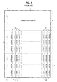
- the base station apparatus of a conventional time-division multiple access (TDMA) cellular mobile communication system is comprised of a common control unit(1)which is connected to a mobile telephone switching office, not shown, to provide overall control of the base station.
- Common control unit (1) is powered by a power supply unit ( 2 )and mounted on an upper shelf ( 3 ) of the apparatus frame with the power supply unit ( 2 ).
- the base station serves two cells to which frequency ranges 1.5 GHz and 800 MHz, for example, are assigned respectively.
- a plurality of radio transceiver panels ( 4 ) are provided which are connected to the common control unit ( 1 ) and commonly powered by a power supply unit 5 .
- Each transceiver panel ( 4 ) has a bandwidth of 0.25 MHz in the 1.5-GHz range and three time slots are multiplexed in the 0.25 MHz band of each transceiver.
- the transceiver panels ( 4 ) and power supply unit( 5 ) are both mounted side by side on a middle shelf ( 6 ).
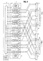
- the output terminal of each transceiver panel ( 4 ) is connected to a frequency division multiplexer ( 7A ) where it is multiplexed with the outputs of other transceivers and supplied to a diplexer ( 9A ) and transmitted from antenna ( 10A ).
- Signals from mobile units located in the 1.5-GHz range cell are received by antenna ( 10A ) and fed through diplexer ( 9A ) to a frequency division demultiplexer ( 8A ) where they are decomposed into individual frequency signals and supplied respectively to transceiver panels ( 4 ).
- a plurality of radio transceivers 14 are provided which are connected to the control unit 1 powered by a power supply unit 15 and mounted side by side on a lower shelf 16.
- Each transceiver panel 14 has a bandwidth of 0.25 MHz in the 800-MHz range and three time slots are multiplexed in the 0.25 MHz band of each transceiver.
- each transceiver panel 14 is connected to a frequency division multiplexer 7B where it is multiplexed with the outputs of other transceivers 14 and supplied to a diplexer 9B and transmitted from antenna 10B.
- Signals from mobile units located in the 800-MHz range cell zone are received by antenna 10B and fed through diplexer 9B to a frequency demultiplexer 8B where they are decomposed into individual frequency signals and supplied respectively to transceiver panels 14.
- the control unit 1 receives an incoming call from the MTSO and, in response, selects one of the transceivers and one of the time slots assigned to it, depending on the destination address of the incoming call, and operates the selected transceiver for transmission to a mobile station. In return, a signal sent from the mobile station is received through demultiplexer 8A by the selected transceiver and applied through control unit 1 to the MTSO.
- WO92/12579 describes a radio transceiver system comprising several transceivers belonging to respective radio systems, an antenna, and a filter connectable to the antenna for filtering signals applied to the antenna and received by the antenna.
- a dividing unit divides the signals received by the antenna to the different transceivers.
- a base station apparatus for a cellular mobile communication system in which different frequency ranges are assigned respectively to cell zones and the base station apparatus serves first and second cell zones, comprising a first power supply unit, a first plurality of transceivers operating in a first radio frequency range assigned to the first cell zone and receiving power from said first power supply unit, a second plurality of transceivers operating in a second radio frequency range assigned to the second cell zone and receiving power from said first power supply unit, a second power supply unit, a third plurality of transceivers operating in said first radio frequency range and receiving power from said second power supply unit, a fourth plurality of transceivers operating in said second radio frequency range and receiving power from said second power supply unit, first combining means for combining outputs of said first and third pluralities of transceivers and transmitting the combined outputs from a first antenna, first decomposing means for decomposing a signal in said first frequency range received by the first antenna into first frequency range individual signals and coupling the first frequency range individual signals to said
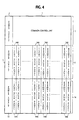
- a base-station apparatus of the present invention wherein parts corresponding to those in Figs. 1 and 2 are indicated by the same numerals as used in Figs. 1 and 2 and operate in the same manner as described previously. It is seen in Fig. 4 that on the middle shelf ( 6 ) a group of 1.5-GHz range transceiver panels ( 34A ) and a group of 800-MHz range transceiver panels ( 34B ) are mounted side by side and on the lower shelf ( 16 ) a group of 1.5-GHz range transceiver panels ( 44A )and a group of 800-MHz range transceiver panels ( 44B ) are mounted side by side.
- All transceiver panels ( 34A ) and ( 34B ) on shelf ( 6 ) are commonly powered by the power supply unit ( 5 ) and all transceiver panels ( 44A ) and ( 44B ) on shelf ( 16 ) are commonly powered by the power supply unit ( 15 ).
- Each of the transceivers ( 34A ) and ( 44A ) has a bandwidth of 0.25 MHz in the 1.5 GHz range, and each of the transceivers ( 34B ) and ( 44B ) has a bandwidth of 0.25 MHz in the 800 MHz range.
- Three time slots are multiplexed into the 0.25-MHz band of each of the transceivers ( 34A ), ( 34B ), ( 44A ) and ( 44B ).
- the outputs of all 1.5-GHz range transceivers (34A) and 44(A) are connected to frequency division multiplexer (7A), while the outputs of all 800-MHz range transceivers ( 34B ) and ( 44B ) are connected to frequency division multiplexer ( 7B ).
- the 1.5-GHz range signals received by antenna ( 10A ) are coupled through diplexer ( 9A ) to frequency division demultiplexer ( 8A ) where they are demultiplexed into individual frequency signals in the 1.5-GHz range.
- These 1.5-GHz time-slot signals are coupled respectively to the transceiver panels ( 34A ) on middle shelf ( 6 ) and transceiver panels ( 44A ) on lower shelf ( 16 ).
- the 800-MHz range signals received by antenna ( 10B ) are coupled through diplexer ( 9B ) to frequency division demultiplexer ( 8B ) where they are demultiplexed into individual frequency signals in the 800-MHz range, which are coupled respectively to the transceiver panels ( 34B ) on shelf ( 6 ) and transceiver panels ( 44B ) on shelf ( 16 ).
- Control unit ( 1 ) monitors the power supply units ( 5 ) and ( 15 ) to isolate those transceivers from the system whose associated power supply unit has failed.
- control unit ( 1 ) makes a search through all the transceivers on shelves ( 6 )and ( 16 ) for an idle one in response to receipt of an incoming call from the MTSO, not shown.
- control unit ( 1 ) isolates them from the system and makes a search exclusively through the transceivers on shelf ( 16 ) for an idle transceiver. Since the power supply unit ( 15 ) still supports the 1.5 GHz and 800 MHz range transceivers on shelf ( 16 ), total service breakdown of one of the cell zones is prevented.
Landscapes
- Engineering & Computer Science (AREA)
- Computer Networks & Wireless Communication (AREA)
- Signal Processing (AREA)
- Mobile Radio Communication Systems (AREA)
Claims (2)
- Basisstationsvorrichtung für ein mobiles Zellenkommunikationssystem, in dem unterschiedliche Frequenzbereiche Zellenzonen zugeordnet sind und die Basisstation erste und zweite Zellenzonen bedient, die aufweist:eine erste Stromversorgungeinheit (5);eine erste Mehrzahl von Transceivern (34A), die in einem ersten Funkfrequenzbereich arbeiten, der der ersten Zellenzone zugeordnet ist, und die Strom von der ersten Stromversorgungseinheit empfangen;eine zweite Mehrzahl von Transceivern (34B) die in einem zweiten Funkfrequenzbereich arbeiten, der der zweiten Zellenzone zugeordnet ist, und die Strom von der ersten Stromversorgungseinheit empfangen;eine zweite Stromversorgungseinheit (15);eine dritte Mehrzahl von Transceivern (44A), die in dem ersten Funkfrequenzbereich arbeiten und Strom von der zweiten Stromversorgungseinheit empfangen;eine vierte Mehrzahl von Transceivern (44B), die in dem zweiten Funkfrequenzbereich arbeiten und Strom von der zweiten Stromversorgungseinheit empfangen;erste Kombiniermittel (7A) zum Kombinieren der Ausgangssignale der ersten und dritten Mehrzahl von Transceivern und zum Senden der kombinierten Ausgangssignale von einer ersten Antenne (10A);erste Zerlegungsmittel (8A) zum Zerlegen eines Signals in den ersten Frequenzbereich, das von der ersten Antenne empfangen ist, in einzelne Signale des ersten Frequenzbereiches und zum Verbinden der einzelnen Signale des ersten Frequenzbereichs mit der ersten und dritten Mehrzahl von Transceivern;zweite Kombiniermittel (7B) zum Kombinieren der Ausgangssignale der zweiten und vierten Mehrzahl von Transceivern und zum Senden der kombinierten Ausgangssignale von einer zweiten Antenne (10B);zweite Zerlegungsmittel (8B) zum Zerlegen eines Signals im zweiten Frequenzbereich, das von der zweiten Antenne empfangen ist, in einzelne Signale im zweiten Frequenzbereich und zum Verbinden der einzelnen Signale im zweiten Frequenzbereich mit der zweiten und vierten Mehrzahl von Empfängern; undeine Steuereinheit (1) zum Überwachen der ersten und zweiten Stromversorgungseinheiten, welche Steuereinheit mit einer Mobilvermittlungsstelle verbunden ist und auf Empfang eines von derselben ankommenden Rufs reagiert, um eine Suche durch alle Transceiver für einen freien Transceiver zu machen, wenn beide Stromversorgungseinheiten normal arbeiten, um eine Suche ausschließlich durch die dritten und vierten Mehrzahlen von Transceivern für einen freien Transceiver zu machen, wenn es bekannt ist, daß die ersten Stromversorgungseinheit versagt hat, und um eine Suche ausschließlich durch die ersten und zweiten Mehrzahlen von Transceivern für einen freien Transceiver zu machen, wenn es bekannt ist, daß die zweite Stromversorgungseinheit versagt hat.
- Basisstationsvorrichtung nach Anspruch 1, bei der die ersten und zweiten Mehrzahlen von Transceivern und die erste Stromversorgungseinheit auf einem ersten Bord (6) und die dritten und vierten Mehrzahlen von Transceivern und die zweite Stromversorgungseinheit auf einem zweiten Bord (16) angebracht sind.
Applications Claiming Priority (2)
| Application Number | Priority Date | Filing Date | Title |
|---|---|---|---|
| JP4295024A JP2836405B2 (ja) | 1992-11-04 | 1992-11-04 | 移動通信用基地局送受信装置 |
| JP295024/92 | 1992-11-04 |
Publications (3)
| Publication Number | Publication Date |
|---|---|
| EP0596727A2 EP0596727A2 (de) | 1994-05-11 |
| EP0596727A3 EP0596727A3 (de) | 1994-10-26 |
| EP0596727B1 true EP0596727B1 (de) | 1999-03-03 |
Family
ID=17815345
Family Applications (1)
| Application Number | Title | Priority Date | Filing Date |
|---|---|---|---|
| EP93308808A Expired - Lifetime EP0596727B1 (de) | 1992-11-04 | 1993-11-04 | Basisstationeinrichtung für Zellularmobilfunk |
Country Status (4)
| Country | Link |
|---|---|
| US (1) | US5430789A (de) |
| EP (1) | EP0596727B1 (de) |
| JP (1) | JP2836405B2 (de) |
| DE (1) | DE69323693T2 (de) |
Families Citing this family (17)
| Publication number | Priority date | Publication date | Assignee | Title |
|---|---|---|---|---|
| JP3166796B2 (ja) * | 1992-07-29 | 2001-05-14 | ソニー株式会社 | コードレス電話 |
| DE4441621A1 (de) * | 1994-11-23 | 1996-05-30 | Philips Patentverwaltung | Funkfeststation |
| US5682403A (en) * | 1995-05-04 | 1997-10-28 | Wavelink Communications | Spread spectrum communication network signal processor |
| FI100040B (fi) * | 1995-11-02 | 1997-08-29 | Nokia Telecommunications Oy | Häiriösuojattu tehonsyöttömenetelmä ja tehonsyöttöjärjestely |
| JPH1023497A (ja) * | 1996-06-13 | 1998-01-23 | At & T Corp | 集中基地局を利用したセルラ無線電話システム |
| US5857144A (en) * | 1996-08-09 | 1999-01-05 | Ericsson, Inc. | In-band vehicular repeater for trunked radio system |
| US6047160A (en) * | 1996-08-29 | 2000-04-04 | Ericsson Inc. | Transportable base station for a trunked radio communication system |
| US6169880B1 (en) | 1996-10-16 | 2001-01-02 | Ericsson Inc. | Method and system of load sharing and prioritization of radio repeaters |
| US6018644A (en) * | 1997-01-28 | 2000-01-25 | Northrop Grumman Corporation | Low-loss, fault-tolerant antenna interface unit |
| US6097966A (en) * | 1997-06-06 | 2000-08-01 | Nortel Networks Limited | Wireless access for local exchange carriers |
| US20060023656A1 (en) * | 2004-07-29 | 2006-02-02 | Anglin Richard L Jr | Interactive digital data broadcasting system |
| US6615024B1 (en) * | 1998-05-01 | 2003-09-02 | Arraycomm, Inc. | Method and apparatus for determining signatures for calibrating a communication station having an antenna array |
| US6490443B1 (en) | 1999-09-02 | 2002-12-03 | Automated Business Companies | Communication and proximity authorization systems |
| US6813505B2 (en) * | 2001-01-05 | 2004-11-02 | Skyworks Solutions, Inc. | Efficient and flexible communication device and system with base-to-base communication |
| US7340280B2 (en) * | 2004-02-26 | 2008-03-04 | Nokia Corporation | Method of configuring base station, and base station |
| CN100421400C (zh) * | 2005-04-07 | 2008-09-24 | 华为技术有限公司 | 一种无线有线网络的综合接入系统 |
| CN101426303B (zh) | 2008-10-27 | 2012-03-21 | 华为技术有限公司 | 通信系统、设备和方法 |
Family Cites Families (6)
| Publication number | Priority date | Publication date | Assignee | Title |
|---|---|---|---|---|
| JPS5292002A (en) * | 1976-01-28 | 1977-08-03 | Mitsubishi Heavy Ind Ltd | Preventing device from implosion in boiler |
| US5084891A (en) * | 1989-09-08 | 1992-01-28 | Bell Communications Research, Inc. | Technique for jointly performing bit synchronization and error detection in a TDM/TDMA system |
| US5212804A (en) * | 1990-08-02 | 1993-05-18 | Gte Airfone, Inc. | Communication system having multiple base stations and multiple mobile units |
| FI88660C (fi) * | 1991-01-09 | 1993-06-10 | Nokia Telecommunications Oy | Radiosaendarmottagarsystem |
| US5243598A (en) * | 1991-04-02 | 1993-09-07 | Pactel Corporation | Microcell system in digital cellular |
| USD342249S (en) | 1992-08-31 | 1993-12-14 | Motorola, Inc. | Enclosure for a multi-unit cellular base station |
-
1992
- 1992-11-04 JP JP4295024A patent/JP2836405B2/ja not_active Expired - Fee Related
-
1993
- 1993-11-04 EP EP93308808A patent/EP0596727B1/de not_active Expired - Lifetime
- 1993-11-04 US US08/145,574 patent/US5430789A/en not_active Expired - Lifetime
- 1993-11-04 DE DE69323693T patent/DE69323693T2/de not_active Expired - Lifetime
Also Published As
| Publication number | Publication date |
|---|---|
| US5430789A (en) | 1995-07-04 |
| JPH06152490A (ja) | 1994-05-31 |
| EP0596727A2 (de) | 1994-05-11 |
| DE69323693T2 (de) | 1999-07-01 |
| JP2836405B2 (ja) | 1998-12-14 |
| DE69323693D1 (de) | 1999-04-08 |
| EP0596727A3 (de) | 1994-10-26 |
Similar Documents
| Publication | Publication Date | Title |
|---|---|---|
| EP0596727B1 (de) | Basisstationeinrichtung für Zellularmobilfunk | |
| US5263047A (en) | Multiple cavity tuning of a transmitter output in a communication system | |
| AU631426B2 (en) | Signal routing system | |
| EP0591491B1 (de) | Grundstation für tdma funkübertragungsanordnung mit frequenzsprung | |
| US6360106B1 (en) | Base station for a radio communications system | |
| US6584116B1 (en) | Method of transmission in a UMTS mobile telephone network enabling preparation for handover to a GSM cell during a call in a UMTS cell | |
| US5276914A (en) | Dual-mode transceiver that switches out a large insertion loss filter during transmission | |
| US5590404A (en) | Base station transmission-reception apparatus for cellular system | |
| AU676331B2 (en) | Mobile radio aerial installation | |
| CN101304279A (zh) | 射频拉远装置及基站系统 | |
| EP0715786B1 (de) | Basisstationsanlage unter verwendung von diversityempfang | |
| CA1263148A (en) | Radio transmitter-receiver system for increasing or decreasing communication channels | |
| WO1995006369A1 (en) | A method for adding capacity of a base station | |
| US5887267A (en) | Bus arbitrators for common local oscillators in cellular radiotelephone base stations | |
| EP0692163B1 (de) | Funkzwischenverstärker | |
| US6157629A (en) | CDMA mobile communication system of automatically changing frequency and method thereof | |
| KR102847905B1 (ko) | 5g 특화망용 이중대역 중계모듈 | |
| JP3177481B2 (ja) | 移動体通信システムの基地局 | |
| JPH0787418B2 (ja) | 制御チャネル構成方法 | |
| JPS6378621A (ja) | 通信衛星用中継器 | |
| HK1011157B (en) | A base station for a frequency hopping tdma radio communication system | |
| JPH01141422A (ja) | ディジタル移動通信システムの通話中チャネル切換方法および移動端末 |
Legal Events
| Date | Code | Title | Description |
|---|---|---|---|
| PUAI | Public reference made under article 153(3) epc to a published international application that has entered the european phase |
Free format text: ORIGINAL CODE: 0009012 |
|
| AK | Designated contracting states |
Kind code of ref document: A2 Designated state(s): BE DE FR GB IT NL SE |
|
| PUAL | Search report despatched |
Free format text: ORIGINAL CODE: 0009013 |
|
| AK | Designated contracting states |
Kind code of ref document: A3 Designated state(s): BE DE FR GB IT NL SE |
|
| 17P | Request for examination filed |
Effective date: 19940915 |
|
| 17Q | First examination report despatched |
Effective date: 19971107 |
|
| GRAG | Despatch of communication of intention to grant |
Free format text: ORIGINAL CODE: EPIDOS AGRA |
|
| GRAG | Despatch of communication of intention to grant |
Free format text: ORIGINAL CODE: EPIDOS AGRA |
|
| GRAH | Despatch of communication of intention to grant a patent |
Free format text: ORIGINAL CODE: EPIDOS IGRA |
|
| GRAH | Despatch of communication of intention to grant a patent |
Free format text: ORIGINAL CODE: EPIDOS IGRA |
|
| GRAA | (expected) grant |
Free format text: ORIGINAL CODE: 0009210 |
|
| AK | Designated contracting states |
Kind code of ref document: B1 Designated state(s): BE DE FR GB IT NL SE |
|
| PG25 | Lapsed in a contracting state [announced via postgrant information from national office to epo] |
Ref country code: SE Free format text: THE PATENT HAS BEEN ANNULLED BY A DECISION OF A NATIONAL AUTHORITY Effective date: 19990303 Ref country code: NL Free format text: LAPSE BECAUSE OF FAILURE TO SUBMIT A TRANSLATION OF THE DESCRIPTION OR TO PAY THE FEE WITHIN THE PRESCRIBED TIME-LIMIT Effective date: 19990303 Ref country code: BE Free format text: LAPSE BECAUSE OF FAILURE TO SUBMIT A TRANSLATION OF THE DESCRIPTION OR TO PAY THE FEE WITHIN THE PRESCRIBED TIME-LIMIT Effective date: 19990303 |
|
| REF | Corresponds to: |
Ref document number: 69323693 Country of ref document: DE Date of ref document: 19990408 |
|
| ITF | It: translation for a ep patent filed | ||
| ET | Fr: translation filed | ||
| NLV1 | Nl: lapsed or annulled due to failure to fulfill the requirements of art. 29p and 29m of the patents act | ||
| PLBE | No opposition filed within time limit |
Free format text: ORIGINAL CODE: 0009261 |
|
| 26N | No opposition filed | ||
| REG | Reference to a national code |
Ref country code: GB Ref legal event code: IF02 |
|
| PGFP | Annual fee paid to national office [announced via postgrant information from national office to epo] |
Ref country code: IT Payment date: 20081127 Year of fee payment: 16 |
|
| PGFP | Annual fee paid to national office [announced via postgrant information from national office to epo] |
Ref country code: FR Payment date: 20081112 Year of fee payment: 16 |
|
| PGFP | Annual fee paid to national office [announced via postgrant information from national office to epo] |
Ref country code: GB Payment date: 20081029 Year of fee payment: 16 |
|
| PGFP | Annual fee paid to national office [announced via postgrant information from national office to epo] |
Ref country code: DE Payment date: 20091029 Year of fee payment: 17 |
|
| GBPC | Gb: european patent ceased through non-payment of renewal fee |
Effective date: 20091104 |
|
| REG | Reference to a national code |
Ref country code: FR Ref legal event code: ST Effective date: 20100730 |
|
| PG25 | Lapsed in a contracting state [announced via postgrant information from national office to epo] |
Ref country code: FR Free format text: LAPSE BECAUSE OF NON-PAYMENT OF DUE FEES Effective date: 20091130 |
|
| PG25 | Lapsed in a contracting state [announced via postgrant information from national office to epo] |
Ref country code: GB Free format text: LAPSE BECAUSE OF NON-PAYMENT OF DUE FEES Effective date: 20091104 |
|
| PG25 | Lapsed in a contracting state [announced via postgrant information from national office to epo] |
Ref country code: IT Free format text: LAPSE BECAUSE OF NON-PAYMENT OF DUE FEES Effective date: 20091104 |
|
| PG25 | Lapsed in a contracting state [announced via postgrant information from national office to epo] |
Ref country code: DE Free format text: LAPSE BECAUSE OF NON-PAYMENT OF DUE FEES Effective date: 20110531 |
|
| REG | Reference to a national code |
Ref country code: DE Ref legal event code: R119 Ref document number: 69323693 Country of ref document: DE Effective date: 20110601 Ref country code: DE Ref legal event code: R119 Ref document number: 69323693 Country of ref document: DE Effective date: 20110531 |