EP0595604A2 - Verfahren und Vorrichtung für ein zusammengesetztes Kurssteuerungssystem - Google Patents
Verfahren und Vorrichtung für ein zusammengesetztes Kurssteuerungssystem Download PDFInfo
- Publication number
- EP0595604A2 EP0595604A2 EP93308543A EP93308543A EP0595604A2 EP 0595604 A2 EP0595604 A2 EP 0595604A2 EP 93308543 A EP93308543 A EP 93308543A EP 93308543 A EP93308543 A EP 93308543A EP 0595604 A2 EP0595604 A2 EP 0595604A2
- Authority
- EP
- European Patent Office
- Prior art keywords
- control
- target value
- virtual
- controlled
- axis
- Prior art date
- Legal status (The legal status is an assumption and is not a legal conclusion. Google has not performed a legal analysis and makes no representation as to the accuracy of the status listed.)
- Granted
Links
Images


Classifications
-
- G—PHYSICS
- G05—CONTROLLING; REGULATING
- G05B—CONTROL OR REGULATING SYSTEMS IN GENERAL; FUNCTIONAL ELEMENTS OF SUCH SYSTEMS; MONITORING OR TESTING ARRANGEMENTS FOR SUCH SYSTEMS OR ELEMENTS
- G05B19/00—Program-control systems
- G05B19/02—Program-control systems electric
- G05B19/18—Numerical control [NC], i.e. automatically operating machines, in particular machine tools, e.g. in a manufacturing environment, so as to execute positioning, movement or co-ordinated operations by means of program data in numerical form
- G05B19/19—Numerical control [NC], i.e. automatically operating machines, in particular machine tools, e.g. in a manufacturing environment, so as to execute positioning, movement or co-ordinated operations by means of program data in numerical form characterised by positioning or contouring control systems, e.g. to control position from one programmed point to another or to control movement along a programmed continuous path
Definitions
- the present invention relates to a course control method for a composite system constituted by a plurality of control systems for generating control inputs for causing controlled objects to follow up desired target values.
- a course control method of this type has been applied to various numerical control apparatuses and the like.
- the above-mentioned course control method is used for position/course control.
- Fig. 31 is a block diagram showing a position control system model for a machine tool. Such a control system is arranged for each axis to constitute a composite control system such as the one shown in Fig. 32.
- a position command value generation means 1 inputs a target value to a control means 2.
- a controlled object 3 feeds back a controlled amount corresponding to a control input, supplied from the control means 2, to another system or the control means 2.
- the control means 2 has gains Wo and Wc/K and a transfer coefficient Wa/s.
- the controlled object 3 has transfer coefficients K/S and 1/S.
- position command value generation means 1a and 1b are arranged for the respective axes to input target values to control means 2a and 2b for the respective axes.
- Controlled objects 3a and 3b for the respective axes feed back controlled amounts corresponding to control inputs, supplied from the control means 2a and 2b, to other systems or the control means 2a and 2b.
- each position control system is constituted by the position command value generation means 1, the controlled object 3, and the control means 2.
- Each position command value generation means 1 outputs a target position/course command signal.
- the controlled object has a drive means to physically move.
- Each control means 2 receives a position command value for each axis component from the position signal generation means 1 and a state amount representing the state of the controlled object 3 and outputs a control input to the controlled object 3 constituted by the corresponding drive means.
- the position control system for each axis is a control system having a position control loop having a relatively low gain and a velocity control loop located inside the position control loop and having a relatively high gain.
- This control system is characterized in that high rigidity can be set against disturbances owing to the high gain of the velocity control loop, and a response without excessive impact on a mechanical system can be easily obtained owing to the low gain of the position control loop.
- the rigidity against disturbances can be greatly increased, thereby eliminating positional errors with respect to stepwise torque disturbances.
- Fig. 33 is a block diagram showing a position control system model of a conventional numerical control apparatus.
- a target value generation means 11 outputs target positions 12a and 12b associated with the respective control axes to control means 13a and 13b.
- Controlled objects 14a and 14b corresponding to the respective axes output controlled amounts 15a and 15b based on control inputs from the control means 13a and 13b.
- a position control system and a velocity control system have loop gains Wo and Wc, respectively, and a constant K is determined by the inertia of a drive system and the gain of a driver.
- the target value generation means 11 calculates target positions corresponding to the respective control axes in accordance with a target course and a target velocity. Position control systems for the respective axes are then formed to follow up the target values, and are independently controlled for the respective axes. When the synchronous relationship between course command values for the respective axes, supplied as target values, are accurately maintained, and the control feed amounts of the respective axes are sufficiently small in a follow-up operation, target course control can be performed by this method.
- Fig. 34 is a schematic view showing an axial feed control system of a conventional position control apparatus.
- a position 32 of the X axis indicates the distance between the centrobaric position of an X axis movable member 35 and an external reference point 31
- a position 33 of the Y axis indicates the distance between the centrobaric position of a Y axis movable member 36 and the centrobaric position of the X axis.
- a position 3 of the Z axis indicates the distance between the centrobaric position of the Y axis movable member 36 and the external reference position 31.
- Control inputs are thrusts 37 and 38 acting on the X and Y axis movable members 35 and 36 in the horizontal direction. In practice, the thrusts 37 and 38 are obtained by supplying power to linear motors or the like.
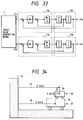
- Fig. 35 is a block diagram showing a control arrangement in the axial feed control system of the position control apparatus shown Fig. 34. The operation of the arrangement will be described below.
- a target value generation means 41 When a target value generation means 41 outputs a target value signal 42 as a position target value for the Z axis, a coarse feed X axis 52a starts to move, and a position (X axis controlled amount) 50a as a controlled amount moves close to the target value.
- a positional error (X axis error signal) 44 becomes smaller than a set value
- a determination means 43 supplies the current positional error 44, as a position command value (Y axis target value), to a Y axis 52b. If the positional error 44 is larger than the set value, the position command value 45 to the Y axis becomes "0". The Y axis moves to coincide with the position command value 45.
- a Z axis controlled amount 54 as the sum of the X axis controlled amount 50a and a Y axis controlled amount 50b coincides with the position target value 42 for the Z axis.
- a controller 55 the following are set: a Y axis error signal 46, an X axis compensator 47a, a Y axis compensator 47b, an X axis control input 48a, a Y axis control input 48b, an X axis controlled object 49a, a Y axis controlled object 49b, a controlled amount 50b, an X axis velocity 51a, and a Y axis velocity 51b.
- the controller 55 has gains Wol, Wo2, M1, and M2 and transfer functions K1/S, K2/S, and 1/S.
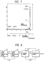
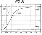
- Fig. 36 shows the response characteristics of the axial feed control system of the position control apparatus shown in Fig. 35.
- the abscissa indicates time (msec); and the ordinate, target values. Note that the target value for the Z axis changes in the form of a ramp, and the final value is "10".
- the determination means 43 when the determination means 43 is set such that the Y axis starts to move when the positional error becomes 0.21, it takes about 36 (msec) for the Z axis to reach 0.2% of the target value.
- the maximum accelerations required for the movement in this case are 1,834 (rad/sec2) for the X axis and 1,284 (rad/sec2) for the Y axis.
- the maximum accelerations are substantially proportional to the power required to move the axes. Since the power which can be normally used is limited, the accelerations must be minimized. In addition, since a vibration produced by a mechanical system is proportional to an acceleration, the maximum accelerations must be minimized.
- a sine (sin) wave and a cosine (cos) wave are given, as position target values, to the X and Y axes.
- An accurate circle can be drawn by causing the X and Y axes to perfectly follow up these target values.
- Fig. 37 is a chart showing traces drawn by an X-Y plotter with two orthogonal axes to which the conventional position control method is applied.
- a trace C0 is a target circular trace.
- the response speeds of the X and Y axes are set to be the same value.
- a trace C1 is obtained.
- the trace C1 becomes a circular trace, although it has a radius smaller than that of the target circle except at the start and end points.
- the position control loop gains of the X and Y axes are set to be different values to perform course control upon changing the response speeds of the X and Y axes.
- a trace C2 is obtained.
- the trace C2 does not coincide with the target circle but becomes an ellipse. It is understood from this example why the X and Y axes need to have the same response speed.
- the trace C1 is obtained, which is a follow-up trace corresponding to a target course set when the response speeds of the X and Y axes are the same.
- the follow-up trace also causes an error with respect to the target circle.
- dR the course error between the target circular course and the follow-up trace in a normal state
- dR Vo2/2RWo2 (where Vo is the velocity, R is the radius, and Wo is the position loop gain).
- the gain of the velocity control loop is set to be high, vibration of the mechanical system is caused. For this reason, the gain cannot be set to be higher than a given value. Therefore, it is difficult to set a high position loop gain, and it is more difficult to make the precision of a trace fall within a target course error as the velocity of a target circular trace is increased and the radius of the circle is decreased.
- Fig. 38 is a chart showing traces drawn by an X-Y plotter with two orthogonal axes to which the conventional position control method is applied, when disturbances are applied.
- a trace C0 is a target circular trace
- a trace C1 is a trace drawn when no disturbances are present.
- a trace C2 is a response trace obtained when a stepwise acceleration disturbance is applied to the X axis while a circle is drawn. As indicated by the trace C2, when disturbances are applied to a controlled object, the course error is increased.
- a trace C3 is a response trace obtained when the gain of the velocity control loop of the same system is doubled. In this case, the course error with respect to the same acceleration disturbance is smaller than that of the trace C2, indicating that an increase in velocity loop gain leads to the suppression of disturbances.
- the gain of the velocity control loop is limited because an increase in gain causes vibration of the mechanical system.
- the acceleration required to suppress disturbances increases. Therefore, it is very difficult to perform course control with high precision while suppressing the influence of disturbances.
- the loop gain of the position control system needs to be increased or a feed forward control system needs to be formed to improve the follow-up characteristics of a servo system. If, however, the follow-up characteristics of the servo system are improved, the following new problems are posed. That is, the capacity of a motor driver is increased, and high-frequency vibration is caused in a mechanical system, resulting in a deterioration in positional precision.
- the gains (Wo1, Wo2, M1, and M2) of the control system shown in Fig. 35 must be increased to increase the response speed and improve the rigidity.
- the maximum accelerations required for movement increase, requiring large power.
- the gains are set to be high, the frequency band of the control system is expanded, causing vibration of the mechanical system.
- the convergence characteristics with respect to a target value may deteriorate.
- this arrangement requires a switching operation near a positional error determination value. Under certain conditions, this switching may cause self-excited oscillation. In this case, the convergence characteristics with respect to a target value deteriorate.
- a position control apparatus In conventional control apparatuses, such as a position control apparatus, a velocity control apparatus, and a temperature control apparatus, a plurality of controlled objects to be simultaneously controlled are present in a composite state. Various types of control operations are performed to cause such a composite control system to reach a target value at a high speed with limited power.
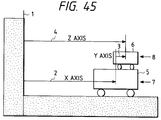
- a position control apparatus has a control system for a composite system such as the one shown in Fig. 45, in which the first axis for coarse feed and the second axis for fine feed are respectively defined as the X and Y axes, and the Z axis is an axis indicating a position where the X and Y axes are synthesized. Control in such a position control apparatus will be described below.
- Fig. 45 is a schematic view showing an axis feed control system of a conventional position control apparatus.
- a position 2 of the X axis indicates the distance between the centrobaric position of an X axis movable member 5 and an external reference point 1
- a position 3 of the Y axis indicates the distance between the centrobaric position of a Y axis movable member 6 and the centrobaric position of the X axis.
- a position 4 of the Z axis indicates the distance between the centrobaric position of the Y axis movable member 6 and the external reference point 1.
- control inputs are thrusts 7 and 8 acting on the X and Y movable members 5 and 6 in the horizontal direction. In practice, the thrusts 7 and 8 are obtained by supplying power to linear motors or the like.
- Fig. 46 is a block diagram showing the first control arrangement in the axial feed control system of the position control apparatus shown in Fig. 45. The operation of the arrangement will be described below.
- a target value signal 12 as a position target value for the Z axis, from a target value generation means 11, an X axis 22a for coarse feed starts to move, and a position (X axis controlled amount) 20a as a controlled amount moves close to the target value.
- a determination means 13 supplies the current positional error 14, as a position command value (Y axis target value) 15, to a Y axis 22b.
- the position command value 15 to the Y axis becomes "0".
- the Y axis 22b moves in accordance with the position command value 15.
- a Z axis controlled amount 24 as the sum of an X axis controlled amount 20a and a Y axis controlled amount 20b coincides with the position target value 12 associated with the Z axis.
- a controller 25 the following are set: a Y axis error signal 16, an X axis compensator 17a, a Y axis compensator 17b, an X axis control input 18a, a Y axis control input 18b, an X axis controlled object 19a, a Y axis controlled object 19b, a Y axis controlled amount 20b, an X axis velocity 21a, and a Y axis velocity 21b.
- the controller 25 has gains Wo1, Wo2, M1, and M2 and transfer functions K1/S, K2/S, and 1/S.
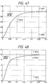
- Figs. 47 and 48 show the response characteristics of the axial feed control system of the position control apparatus shown in Fig. 46.
- the abscissa indicates time (msec); and the ordinate, target values. Note that these graphs respectively correspond to cases where target values associated with the Z axis are set to be "1" and "10".
- the determination means 13 is set such that the Y axis starts to move when the positional error becomes 0.01, it takes about 30 (msec) for the Z axis to reach 0.1% of the target value.
- the maximum accelerations required for the movement are 1,600 (rad/sec2) for the X axis and 1,870 (rad/sec2) for the Y axis.
- the maximum accelerations are substantially proportional to the power required to move the axes. Since the power which can be normally used is limited, the accelerations must be minimized. In addition, since a vibration produced by a mechanical system is proportional to an acceleration, the maximum accelerations must be minimized.
- this arrangement requires a switching operation near a positional error determination value. Under certain conditions, this switching may cause self-excited oscillation. In this case, the convergence characteristics with respect to a target value deteriorate.
- the determination means 13 is set such that the Y axis starts to move when the positional error becomes 0.21, it takes about 30 (msec) for the Z axis to reach 0.1% of the target value.
- the maximum accelerations required for the movement are 2,300 (rad/sec2) for the X axis and the 2,500 (rad/sec2) for the Y axis.
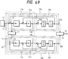
- Fig. 49 is a block diagram showing the second control arrangement in the axial feed control system of the position control apparatus shown in Fig. 45.
- the same reference numerals in Fig. 49 denote the same parts as in Fig. 46.
- disturbances 26a and 26b are respectively applied to the X and Y axes.
- Fig. 50 is a graph showing the behavior of the axial feed control system of the position control apparatus shown in Fig. 46 against the disturbances.
- the abscissa indicates time (sec); and the ordinate, target values. Note that this graph corresponds to a case where a target value associated with the Z axis is set to be "10".
- the control system operates in the same manner as in the case where a deviation is caused when a target value is applied. More specifically, an X axis compensator 17a generates a thrust to reduce this deviation to "0", thus moving the X axis 22a.
- the positional error of the X axis 22a becomes smaller than a set value in a determination means 13
- the Y axis starts to move, thus quickly reducing the deviation caused by the disturbance to "0".
- the X axis 22a operates to reduce the positional error to "0" by itself at first.
- a stepwise disturbance is applied to the X axis, and the X axis operates to reduce the positional error to "0" by itself at first.
- the positional error becomes smaller than the set value in the determination means 13, and the X axis starts to move.
- the gains Wo1, Wo2, M1, and M2 of the control system are increased to obtain a satisfactory response speed, rigidity, and the like. If, however, the gains Wo1, Wo2, M1, and M2 are increased, the maximum accelerations required for the movement are increased, requiring large power. Furthermore, similar to the above-described case, if the gains are increased, vibration of the mechanical system is caused, and convergence characteristics with respect to a target value deteriorate. It is, therefore, difficult to increase the response speed and improve rigidity with respect to disturbances in control of the composite system.
- the present invention has been made to solve the above problems, and has its object to provide a composite system course control method and apparatus which can perform high-speed, high-precision course control without increasing the gain of each control system by calculating/outputting control inputs for minimizing a predetermined evaluation function while causing target values set for reality axes as controlled objects, state amounts from the respective controlled objects, and disturbances to interfere with a target value set for a virtual axis as a virtual controlled object, a state amount from the virtual controlled object, and disturbances.
- a composite system course control method comprising the steps of producing a target value for moving a controlled object as a reality axis by a desired amount and a virtual target value for moving a virtual controlled object as a virtual axis based on the reality axis, calculating a control input and a virtual control input which optimize a predetermined first evaluation function upon receiving the produced virtual target value, the produced target value, a virtual state amount from the virtual controlled object, a state amount from the controlled object, a first disturbance signal with respect to the virtual controlled object, and a second disturbance signal with respect to the controlled object, and outputting the calculated control input and the calculated virtual control input to the virtual controlled object and the controlled object, respectively.
- a composite system course control apparatus comprising target value production means for producing a target value for moving a controlled object as a reality axis by a desired amount, virtual target value production means for producing a virtual target value for moving a virtual controlled object as a virtual axis based on the reality axis, and control means for calculating a control input and a virtual control input which optimize a predetermined first evaluation function upon receiving the produced virtual target value, the produced target value, a virtual state amount from the virtual controlled object, a state amount from the controlled object, a first disturbance signal with respect to the virtual controlled object, and a second disturbance signal with respect to the controlled object, and for outputting the calculated control input and the calculated virtual control input to the virtual controlled object and the controlled object, respectively.
- a composite system course control apparatus comprising target value production means for producing target values for moving a plurality of controlled objects by desired amounts, and control means for calculating control inputs for optimizing a predetermined second evaluation function upon receiving the target values, state amounts from the controlled objects, and disturbance signals with respect to the controlled objects, and for outputting the control inputs to the controlled objects.
- the first evaluation function includes a first or second weighting function component for evaluating a course error.
- the second evaluation function includes a first or second weighting function component for evaluating a course error.
- a composite system course control apparatus comprising target value production means for producing target values for moving a plurality of controlled objects by desired amounts, target value conversion means for converting the target values produced by the target value production means into new target values, and control means for calculating control inputs for optimizing a predetermined second evaluation function upon receiving the converted target values output from the target value conversion means, state amounts from the controlled objects, and disturbance signals with respect to the controlled objects, and for outputting the control inputs to the controlled objects.
- a target value for moving a controlled object as a reality axis by a desired amount is produced.
- a virtual target value for moving a virtual controlled object as a virtual axis based on the reality axis is produced.
- a control input and a virtual control input which optimize the predetermined first evaluation function are calculated upon reception of the produced virtual target value, the produced target value, a virtual state amount from the virtual controlled object, a state amount from the controlled object, a first disturbance signal with respect to the virtual controlled object, and a second disturbance signal with respect to the controlled object.
- the calculated control input and the calculated virtual control input are then output to the virtual controlled object and the controlled object, respectively. With this operation, the course error can be minimized without changing the maximum accelerations with respect to disturbances.
- the control means when the target value production means produces a target value for moving a controlled object as a reality axis by a desired amount, and the virtual target value production means produces a virtual target value for moving a virtual controlled object as a virtual axis based on the reality axis, the control means then calculates a control input and a virtual control input which optimize the predetermined first evaluation function upon receiving the produced virtual target value, the produced target value, a virtual state amount from the virtual controlled object, a state amount from the controlled object, a first disturbance signal with respect to the virtual controlled object, and a second disturbance signal with respect to the controlled object.
- the control means outputs the calculated control input and the calculated virtual control input to the virtual controlled object and the controlled object, respectively. With this operation, control inputs for minimizing the course error can be output without changing the maximum accelerations with respect to disturbances.
- control means calculates control inputs for optimizing the predetermined second evaluation function upon receiving the target values, state amounts from the controlled objects, and disturbance signals with respect to the controlled objects, and outputs the control inputs to the controlled objects. With this operation, control inputs for minimizing the course error can be output.
- the first evaluation function includes the first or second weighting function component for evaluating a course error, a follow-up operation with respect to target values can be performed without increasing the accelerations.
- the target value conversion means converts the target values produced by the target value production means into new target values, and outputs the new target values to the control means.
- the control means calculates control inputs for optimizing a predetermined second evaluation function upon receiving the converted target values output from the target value conversion means, state amounts from the controlled objects, and disturbances with respect to the controlled objects. The control means then outputs the control inputs to the controlled objects. With this operation, the course error can be minimized without increasing the accelerations.
- the target value conversion means converts the target values produced by the target value production means into new target values, and outputs the new target values to the control means.
- the control means calculates control inputs for optimizing a predetermined second evaluation function upon receiving the converted target values output from the target value conversion means, state amounts from the controlled objects, and disturbance signals with respect to the controlled objects. The control means then outputs the control inputs to the controlled objects. With this operation, the course error can be minimized without increasing the accelerations.
- the present invention has been made to solve the above-described problems, and has as its object to provide a control apparatus for a composite control system, which determines control inputs to be input to controlled objects while causing errors between controlled amounts obtained from the respective control systems and target values to interfere with each other, thereby greatly improving the response characteristics with respect to the overall controlled amount as the sum of the controlled amounts of the respective controlled objects of the composite system, and causing stationary errors by disturbance application to quickly converge.
- a control apparatus for a composite control system comprising target value production means for producing desired target value signals on the basis of target value, a plurality of addition means for respectively adding controlled amounts from controlled objects of control systems and the target value signals and outputting error signals for the respective control systems, and compensation means for compensating/calculating control inputs for optimizing a first evaluation function upon receiving the error signals output from the addition means and the controlled amounts output from the respective controlled objects, the control inputs being output to the respective controlled objects.
- a control apparatus for a composite control system comprising target value production means for producing desired target value signals on the basis of target values, a plurality of addition means for respectively adding controlled amounts from controlled objects of control systems and the target value signals and outputting error signals for the respective control systems, and compensation means for compensating/calculating control inputs for optimizing a second evaluation function upon receiving the error signals output from the addition means, the controlled amounts output from the controlled objects, and either or both of disturbances applied to the respective controlled objects.
- the compensation means calculates and outputs a control input for compensating characteristics of each controlled object on the basis of an integral value of the error signal from each of said addition means or a value obtained by multiplying the integral value by a predetermined weight.
- the compensation means compensates/calculates and outputs control inputs for optimizing the first evaluation function to the respective controlled objects, while causing the error signals output from the addition means and the controlled amounts output from the controlled objects to interfere with each other.
- the response speed with respect to controlled amount of a composite purpose can be increased without increasing the gain of each control system.
- the compensation means calculates control inputs for optimizing the second evaluation function and outputs them to the respective controlled objects, while causing the error signals output from the addition means, the controlled amounts output from the controlled objects, and either or both of the disturbances applied to the controlled objects to interfere with each other. With this operation, stationary errors caused by disturbances acting on the target composite controlled amount can be caused to converge at a high speed.
- the compensation means calculates and outputs control inputs for compensating the characteristics of the respective controlled objects on the basis of the integral values of error signals from the respective addition means or values obtained by multiplying the integral values by predetermined weights. Therefore, stationary errors caused by stepwise disturbances can be quickly eliminated.
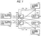
- Fig. 1 is a block diagram for explaining the arrangement of a composite system course control apparatus according to an embodiment of the present invention.
- position command value generation means 100a and 100b respectively output target values associated with the respective axes to control means 104a and 104b for the respective axes.
- the control means 104a and 104b each having a CPU, a ROM, and a RAM (none of which are shown), respectively calculate control means 104a and 104b for minimizing an evaluation function J (k) defined by equation (1) by using an evaluation function obtained by integrating the evaluation function J (k) by a finite time in a quadratic form, on the basis of inputs Ila, I2a, I3a, Ilb, I2b, and I3b.
- control means 104a and 104b then output the control inputs 104a and 104b to controlled objects 102a and 102b, respectively.
- control means 104a and 104b perform calculation by a DP (dynamic programming) method.
- Each of the weighting functions Q and X includes either
- 2 - (e, ⁇ y)2, (where R is the target vector, y is the follow-up course vector, e ( R - Y) is the course error vector, ⁇ y is the follow-up course velocity vector, and ⁇ R is the target value velocity vector), or an element term mathematically equivalent thereto.
- X (k+1) A (k) X (k) + B (k) U (k) + D (k) W (k)
- X is the state vector
- U is the control input vector
- W is the disturbance vector
- U (U1, U2, U3)
- U1: X axis control input U2: Y axis control input U3: Z axis control input W (W1, W2, W3)
- the X and Y axes are control axes which exist in reality, whereas the Z axis is a virtual control axis which does not exist in reality.
- a target value for the Z axis is the position of "0" at a start point and moves to a certain position at a constant velocity, and target values for the X and Y axes start to move therefrom.
- the position of the Z axis is held while the target values for the X and Y axes move.
- the Z axis returns to the position of "0" at the same velocity as that in the starting operation when the target values for the X and Y axes stop.
- the disturbance acting on the X axis can be measured in advance.
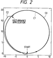
- Fig. 2 shows traces drawn by an X-Y plotter with two orthogonal axes to which the course control apparatus shown in Fig. 1 is applied. In order to show an improved state of a course error, Fig. 2 is caused to correspond to a state where the error is increased 10 times in the radial direction.
- a trace C0 is a target circular trace
- a trace C1 is drawn in the absence of disturbances
- a trace C2 is drawn when a stepwise disturbance is applied.
- the same target position commands as those in the case shown in Fig. 38 are given to the X and Y axes, and the same disturbance as that in the case shown in Fig. 38 is applied to the X axis.
- parameters are selected such that when the same acceleration disturbance as that in Fig. 38 is applied, the same maximum accelerations as those in the prior art are used to suppress the disturbance.
- the radius error with respect to the same disturbance is reduced to about 1/10 that in the prior art. That is, an increase in precision can be achieved.
- setting of the same maximum accelerations means that the power consumption of the driver of each motor is the same as that in the prior art, provided that disturbances, friction, and the like are neglected.
- the control method of the embodiment better follow-up characteristics with respect to a target value and better rigidity against disturbances can be obtained, while course control can be performed at a higher speed and with higher precision by the drivers having the same capacities as those in the prior art.
- accelerations cause vibration of the mechanical system.
- the control method of the embodiment can perform course control at a higher speed with higher precision than the conventional method having the vibration of the mechanical system.
- the weighting function Q in the evaluation function defined by equation (1) is a function of the magnitude of the target value vector R, but the weighting function H is a constant value. Note that the weighting function H may also be a function of the magnitude of the target value vector R in accordance with the purpose of control.
- a simpler control arrangement can be realized by using a disturbance signal predicted from, e.g., a course target value and a controlled object model.
- a disturbance signal predicted from, e.g., a course target value and a controlled object model.
- nonlinear friction caused when the machine moved in a reverse direction can be predicted from a controlled object model and a target command value.
- the present invention can be easily applied to the machine tool.
- a detector for measuring a disturbance signal may be arranged independently of a state amount detector.
- Fig. 3 is a block diagram for explaining another arrangement of the composite system course control apparatus shown in Fig. 1. More specifically, this arrangement corresponds to a case where control is performed by using a virtual axis, i.e., a case where two reality axes (X and Y axes) as controlled objects and one virtual axis (Z axis) as a control system are combined together.
- a virtual axis i.e., a case where two reality axes (X and Y axes) as controlled objects and one virtual axis (Z axis) as a control system are combined together.
- a position command value generation means 110 supplies target values for the respective axes (X and Y axes) to control means 114 and 120.
- the control means 114 includes a CPU, a ROM, and a RAM to perform minimization processing on the basis of an evaluation function corresponding to equation (1).
- a controlled object 112 receives each axis control input from the control means 114 and moves each axis by a predetermined amount.
- Disturbance measurement means 113a and 113b supply measured disturbances to the control means 114 and 120, the controlled object 112, and a virtual controlled object 115, respectively.
- a virtual position command value generation means 116 supplies a target value for one virtual axis (to be referred to as the Z axis) to the control means 114 and 120.
- the control means 114 and 120 receive the generated virtual target value and target values, a virtual state amount from the virtual controlled object, state amounts from the controlled objects, the first disturbance signal with respect to the virtual controlled object, the second disturbance signal with respect to the controlled objects, and calculate control inputs and a virtual control input which optimize a predetermined first evaluation function (equation (1) or the like).
- the control means 114 and 120 then output the calculated control inputs and virtual control input to the corresponding virtual controlled object and control objects. With this operation, control inputs which can minimize the course error without changing the maximum accelerations with respect to disturbances can be output.
- the composite system course control apparatus shown in Fig. 3 is characterized in that a virtual course command signal for a virtual controlled object is obtained from course command signals for the reality controlled objects.
- the virtual axis may be replaced with N spatial reality axes and M virtual axes (N and M are arbitrary integers).
- N and M are arbitrary integers.
- the embodiment is characterized by introducing a virtual axis (controlled object) which does not exist, that the virtual axis does not exist means that the virtual axis is not associated with the purpose of control.
- whether the virtual axis Z physically exist or not is irrelevant to the embodiment. That is, the virtual axis Z may physically exist, but its purpose is to control the X and Y axes. Therefore, whether the virtual axis Z (an axis set such that the state amount of a virtual controlled object which does not physically exist has a mathematically orthogonal relationship with the state amount of a controlled amount which exists) actually moves is not irrelevant to the embodiment.
- an evaluation function is employed in consideration of disturbances applied to the respective courses.
- a predetermined evaluation function may be determined on the basis of the state amounts of the controlled objects 102a and 102b and output signals from the position command value generation means 100a and 100b so that the control means 104a and 104b respectively determine control inputs to the controlled objects 102a and 102b.
- target values for moving controlled objects as reality axes by desired amounts and a virtual target value for moving a virtual controlled object as a virtual axis based on the reality axes are generated, and control inputs for optimizing a predetermined first evaluation function and a virtual control input are calculated by inputting the generated virtual target value and target values, a virtual state amount from the virtual controlled object, state amounts from the controlled objects, the first disturbance signal with respect to the virtual controlled object, and second disturbance signals with respect to the controlled objects.
- the calculated control inputs and virtual control input are then output to the corresponding virtual controlled object and controlled objects, thereby minimizing the course errors without changing the maximum accelerations with respect to the disturbances.
- Fig. 4 is a block diagram for explaining the arrangement of a composite system course control apparatus according to the second embodiment of the present invention.
- a position command value generation means 121 outputs a target value for each reality controlled object 122 as two spatial reality axes to a control means 123a and outputs the same target value to a control means 128 for controlling a virtual controlled object 124.
- a virtual position command value generation means 125 outputs a virtual target value for the virtual controlled object 124 to a control means 123b and outputs the same virtual target value to the control means 123a.
- Each of the control means 123a and 123b includes a CPU, a RAM, and a ROM.
- Each control means receives state amounts corresponding to the reality axis control system and the virtual axis, the above-mentioned virtual target value, and the above-mentioned target value, and calculates control inputs and a virtual control input which optimize an evaluation function based on equation (1). These control inputs are then output to reality controlled object 122 and the virtual controlled object 124, respectively.
- the X and Y axes are control axes which exist in reality, but the Z axis is a virtual control axis which does not exist in reality and which is a characteristic feature of the present invention.
- the Z axis may exist in reality, an arbitrary controlled object which does not exist and a target value are introduced in accordance with the purpose of control.
- the characteristics of the Z axis are set to be the same as those of the X axis. Assume that a target value for the Z axis is at the position of "0" at a start point and moves to a certain position at a constant velocity, and target values for the X and Y axes start to move therefrom. The Z axis returns to the position of "0" at the same velocity as that in the starting operation when the target values for the X and Y axes stop.
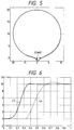
- Fig. 5 shows traces drawn by using the composite system course control apparatus shown in Fig. 4, e.g., an X-Y plotter with two orthogonal axes.
- Fig. 5 is caused to correspond to a state where the error is increased 20 times in the radial direction.
- the broken line indicates a target circular trace; and the solid line, a controlled trace.
- parameters are selected to set the same maximum accelerations as those in the conventional method shown in Fig. 38.
- the radius error with respect to the same disturbance is reduced to about 1/10 that in the prior art. That is, an increase in precision can be achieved.
- the control method of the embodiment allows the corresponding axis to move at a velocity about three times that in the conventional control method, thus realizing high-speed control.
- setting of the same maximum accelerations means that the power consumption of the driver of each motor is the same as that in the prior art, provided that disturbances, friction, and the like are neglected.
- accelerations cause vibration of the mechanical system.
- the control method of the embodiment can perform course control at a higher speed with higher precision than the conventional method owing to the vibration of the mechanical system.
- one reality spatial axis and one virtual axis may be controlled such that the time waveform of the one spatial reality axis is controlled in accordance with a purpose.
- a state of variation in control characteristics in a case where one spatial reality axis and one virtual axis are controlled will be described below with reference to Figs. 6 and 7.
- Fig. 6 shows response characteristics with respect to a target value in the course control apparatus shown in Fig. 4.
- the abscissa indicates time; and the ordinate, a moving amount.
- a curve C4 corresponds to response characteristics in a case where no target command value is given to the virtual axis
- a curve C3 corresponds to response characteristics in a case where a target command value is given to the virtual axis upon completion of a command with respect to the reality axis.
- Fig. 7 is a graph showing a physically analyzed state of the response characteristics shown in Fig. 6.
- the same reference numerals in Fig. 7 denote the same parts as in Fig. 6. Referring to Fig. 7, the abscissa indicates the virtual axis; and the ordinate, the reality axis.
- the response characteristic curve C4 in a virtual space is a target course having a line segment moving from the left to the right on the reality axis (X axis), and the response characteristic curve C3 is a target course curving at a right angle in the virtual space defined by the reality axis (X axis) and the virtual axis (Z axis).
- each of weighting functions Q and X in an evaluation function includes either
- the present invention is applied to combinations of a controlled object having two reality two axes and one virtual axis, and a controlled object having one spatial reality axis and one virtual axis. It is, however, apparent that the present invention can be applied to a combination of N spatial axes and M virtual axes (N and M are arbitrary integers).
- the second embodiment is characterized in that a virtual axis (controlled object) is introduced.
- the virtual axis does not exist means that the virtual axis is not associated with the purpose of control.
- the virtual axis Z in the second embodiment may physically exist, but the purpose is to control the X axis. That is, whether the virtual axis Z physically exist or not is irrelevant to the embodiment.
- Fig. 8 is a block diagram for explaining the basic arrangement of a composite system course control apparatus according to the third embodiment of the present invention.
- a target value generation means 131 outputs a target value 132 for a controlled object 137 to a target value conversion means 133.
- the target value conversion means 133 produces a new target value 134 by adding a proper interpolation point to the target value 132 according to a predetermined algorithm when the acceleration of the target value is excessively large.
- the target value conversion means 133 supplies the new target value 134 to a control means 135.
- the control means 135 has a CPU, a ROM, a RAM, and the like to sequentially calculate and output a control input 136 for minimizing a predetermined evaluation function J (K) defined by equation (4) (to be described later) upon receiving a state amount 139 of the controlled object, the new target value 134, and a control amount 138 of each control axis as the controlled object.
- J evaluation function
- the target value conversion means 133 adds an interpolation point to the target value 132, a time delay corresponding to the number of added target values occurs.
- a control signal 140 serves to set the target value generation means 131 in a standby state to prevent it from generating a new target value during this delay period.
- J (K) ⁇ [
- ei is the positional error vector
- u i is the control input vector
- ⁇ R i is the target value velocity vector
- q1 is the area term weighting coefficient
- H is the control input weighting coefficient.
- the target value conversion means converts the generated target values into new target values, and outputs them to the control means.
- the control means receives the converted target values, state amounts from the controlled objects, and disturbance signals associated with the controlled objects, and calculates control inputs for optimizing a predetermined second evaluation function.
- the control means then outputs the control inputs to the controlled objects, thereby minimizing the course errors without increasing the accelerations.
- Fig. 9 is a block diagram showing the detailed arrangement of an apparatus having a composite control system to which the course control apparatus according to the third embodiment is applied.
- the same reference numerals in Fig. 9 denote the same parts as in Fig. 8.
- a target value 132a for an X axis controlled object 139a is input to a target value conversion means 133.
- the target value conversion means 133 produces a new target value 134a by adding a proper interpolation point to the target value 132a according to a predetermined algorithm when the acceleration of the target value 132a is excessively larger.
- the target value conversion means 133 then supplies the new target value 134a to an adder 135a.
- a target value 132b for a Y axis controlled object 139b is input to the target value conversion means 133.
- the target value conversion means 133 produces a new target value 134b by adding a proper interpolation point to the target value 132a when the acceleration of the target value 132b is excessively large according to a predetermined algorithm.
- the target value conversion means 133 then supplies the new target value 132b to an adder 135b.
- a compensator 137 receives an addition signal 136a based on a controlled amount 140a from the controlled object 139a and the new target value 134a, the new target value 134a, an addition signal 136b based on a state amount 141a of the controlled object 139a, a controlled amount 140b from the controlled target 139b, and the new target value 134b, the new target value 134b, a state amount 141b of the controlled target 139b, and the like, thus sequentially calculating control inputs 138a and 138b for minimizing the predetermined evaluation function J (K) defined by equation (4).
- the compensator 137 then outputs the control inputs 138a and 138b to the controlled objects 139a and 139b, respectively.
- Figs. 10A and 10B are block diagrams showing the arrangements of models of the controlled objects 139a and 139b shown in Fig. 9.
- each model has transfer coefficients K/S and 1/S, a constant K is determined by the inertia of a drive system, the gain of a driver, and the like.
- a target command value is converted by using the following simple algorithm.
- conversion algorithm for target command value Conversion algorithm:
- an acceleration A K calculated from a current target position R K (a target value vector having a position target value for each axis at time k as a component) exceeds a set maximum acceleration A m , an intermediate point ⁇ (R K /2) + (R K-1 /2) ⁇ between the current target position R K and a preceding target position R K-1 is set as a current target value.
- Figs. 11A and 11B are graphs, each showing the relationship between an increase in position target value (velocity) of a target course and an acceleration component in the composite system course control apparatus according to the present invention.
- Fig. 11A corresponds to a case where the above-described conversion algorithm for target command values is not executed.
- Fig. 11B corresponds to a case where the conversion algorithm for target command values is executed, and more specifically, a case wherein a semicircular trace as a course is obtained with a radius of 108 (mm) and a target velocity of 100 (mm/sec) constituting a target position command value. Note that a target value is given to the control system in practice is at the position of the integral value of this velocity component.
- FIG. 11B since accelerations at the start and end points of the target course are large, simple acceleration processing is performed at these points.
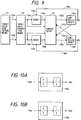
- Figs. 12A and 12B respectively show response characteristics with respect to such target values.
- Figs. 12A and 12B are graphs showing course follow-up characteristics with respect to the target values shown in Figs. 11A and 11B.
- Fig. 12A corresponds to a case wherein the above-described conversion algorithm for target command values is not executed.
- Fig. 12B corresponds to a case where the conversion algorithm for target command values is executed. Note that in order to clarify the degree to which a course error is improved, these graphs are caused to correspond to states and characteristics obtained when the error is increased 100 times in the radial direction.
- Fig. 12A shows a follow-up characteristic curve C2 of a predictive control system and a follow-up characteristic curve of a conventional control system in a case where parameters for the control system are selected such that the maximum course error becomes the same value (about 25 (um)) as that of the position target value in Fig. 11A.
- Fig. 12B shows a follow-up characteristic curve C4 of the predictive control system and a follow-up characteristic curve C3 of the conventional system with respect to the position target value in Fig. 11B.
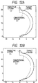
- Figs. 13 to 16 are graphs showing the acceleration response waveforms, of the X and Y axes, corresponding to the follow-up characteristics shown in Figs. 11A to 12B. More specifically, Figs. 13 and 15 correspond to acceleration response waveforms of the follow-up characteristic curve C1 and the follow-up characteristic curve C2 of the predictive control system in the case wherein the conversion algorithm for target command values is not executed. Figs. 14 and 16 correspond to the acceleration response waveforms of the follow-up characteristic curve C3 and the follow-up characteristic curve C4 of the predictive control system in the case where the conversion algorithm for target command values is executed.
- the maximum accelerations of the follow-up characteristic curve C2 of the predictive control system and the follow-up characteristic curve of the conventional control system are 2,819 (mm/sec) and 17,338 (mm/sec), respectively.
- the conversion algorithm for target command values is executed, in which the maximum accelerations of the follow-up characteristic curve C4 of the predictive control system and the follow-up characteristic curve C3 of the conventional control system are 2,328 (mm/sec) and 9,666 (mm/sec), respectively. That is, both the maximum course error and the maximum acceleration in the predictive control system are smaller than those in the conventional control system, and the vibration of the acceleration waveform in the predictive control system is also smaller than that in the conventional control system.
- the problems posed in the conventional simple acceleration/deceleration method can be solved. More specifically, in the conventional simple acceleration/deceleration method, since a large number of high-frequency components are included in an acceleration waveform, vibration of a mechanical system is caused, resulting in poor controllability. In addition, in order to perform control with a small amount of vibration, an acceleration/deceleration method needs a sufficient care. Furthermore, the simple acceleration/deceleration method can be applied to only specific courses, e.g., a straight course and an arcuated course. These problems, however, can be solved by the present invention.
- position information of each axis (obtained by integrating velocity information in the embodiment) is used.
- velocity information of each axis may be used instead.
- the embodiment exemplifies the course control system for simultaneously controlling a plurality of axes.
- the present invention can be applied to position control of one axis and may be applied to a velocity control system using velocity information as a target value.
- an intermediate point ⁇ (R K /2) + (R k-1 /2) ⁇ between the current target position R K and a preceding target position R K-1 is set as a current target value.
- another point on the target course may be set as a current target value.
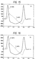
- Figs. 17A and 17B are views showing methods of selecting interpolation points for a target course in the composite system course control apparatus of the present invention.
- Fig. 17A corresponds to a case wherein interpolation points R KK are selected to be located on joined straight lines.
- Fig. 17B corresponds to a case wherein the interpolation points R KK are selected to be located on an arc.
- the black dots indicate given target positions; and the white dots, the interpolation points R KK .
- the interpolation points R KK may be selected to be located on joined straight lines, or may be selected to be located on an arc if it is known beforehand that a target course is smooth. In this case, an arc passing through three points including current and past points is obtained, and interpolation points are selected to be located on the arc, thereby obtaining optimal interpolation points.
- an area component S K as shown in Fig. 18 is used as an element for evaluating a course error. More specifically, in the embodiment, while a course error is compensated between the respective axes in such a manner that the sum of the area components enclosed with curves as a target course R and a follow-up course C is caused to infinitely approach zero, controlled objects 150a (X axis) and 150b (Y axis) shown in Figs. 20A and 20B are optimized on the basis of the evaluation function (equation (4)).
- An area error component (area error term) S ik in one interval can be expressed by a vector relationship, as shown in Fig. 19. Note that Fig. 19 also shows a position error vector e k .
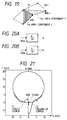
- Fig. 21 shows a trace of a target course C1 and a trace of a follow-up course C2 in a case wherein a circle is drawn after optimal control inputs for minimizing the evaluation function are obtained by the course control system having the above-described arrangement.
- the radius of the target circular course is set to be 10 (mm)
- the moving velocity is set to be 150 (mm/sec). Since a course error in the follow-up course is very small, the follow-up course is displayed after the error is increased 100 times in the radial direction.
- the maximum course error which is 77 ( ⁇ m), occurs at the start point.
- an increase in precision in course control can be realized without using a large acceleration.
- an area error term of the above-mentioned evaluation function an area error term other than a current term, for example, a preceding term or a succeeding term, i.e.,
- 2 - (e i , ⁇ y i ) (where i ⁇ 1, ⁇ 2,.7) is used.
- Fig. 22 is a block diagram for explaining the basic arrangement of a course control apparatus according to the fourth embodiment of the present invention.
- a position command value generation means 151a outputs a target value for the X axis to control means 152a and 152b.
- a position command value generation means 151b outputs a target value for the Y axis to the control means 152a and 152b.
- Each of the control means 152a and 152b includes a CPU, a ROM, a RAM, and the like to minimize an evaluation function j (K) defined by equation (5) upon receiving the respective target values and state amounts and controlled amounts from controlled objects 153a and 153b.
- ei is the positional error vector
- u i is the control input vector
- ⁇ R i is the target value velocity vector
- q1 is the area term weighting coefficient
- H is the control input weighting coefficient.
- the weighting coefficients q1 and q2 of area error terms at the current and succeeding sampling time points are set to be the same value. However, these weighting coefficients q1 and q2 may be set to be different values.
- a position error term and an acceleration term are used for the evaluation function as well as the area term
- a control system may be formed by introducing an acceleration change term, a velocity term, and the like into the evaluation function in addition to the above-mentioned terms.
- a trace of a target course C1 and a trace of a follow-up course C2 shown in Fig. 23 are obtained when a circle is drawn.
- the maximum target velocities (150 mm/sec) shown in Figs. 21 and 23 are set when weighting coefficients of the control system are selected to set the same acceleration.
- the course error is increased 100 times in the radial direction. More specifically, the maximum error, which is 35 (um), occurs at an end point.
- an area error term other than a current term for example, a preceding term or a succeeding term, i.e.,
- the course error characteristics can be greatly improved as compared with the above-described embodiment.
- Figs. 24 to 26 show course error characteristics in the course control apparatus shown in Fig. 22.
- Fig. 24 shows maximum radius error characteristics.
- Fig. 25 shows radius error characteristics in a normal state.
- Fig. 26 shows maximum acceleration characteristics.
- the abscissa indicates the moving velocity.
- position information obtained by integrating velocity information
- velocity information of each axis may be used instead.
- Fig. 27 is a block diagram for explaining the basic arrangement of a course control apparatus according to the fifth embodiment of the present invention.
- a target value generation means 161 outputs a desired target value signal 162 to a target value production means 163 of a controller 175.
- the target value production means 163 produces an X axis target value 164a on the basis of the input target value signal 162, and outputs the X axis target value 164a to an adder 165a.
- the target value production means 163 also produces a Y axis target value 164b and outputs it to an adder 165b.
- the adder 165a adds the X axis target value 164a to an X axis controlled amount 170a and outputs an X axis error signal 166a to a compensator 167.
- the adder 165b adds the Y axis target value 164b to a Y axis controlled amount 170b and outputs a Y axis error signal 166b to the compensator 167.
- a virtual target value generation means 176 outputs a virtual target value to the compensator 167.
- a virtual controlled object 178 is set in accordance with the purpose of control of controlled objects 169a and 169b.
- a virtual state amount 179 of the virtual state amount 179 is input to the compensator 167 in advance.
- An adder 173 adds an X axis weight 172a and a Y axis weight 172b to produce a Z axis controlled amount 174.
- the target value production means 163 produces the target values 164a and 164b such that the sums of the target values 164a and 164b for the respective controlled objects and the desired target value signal 162 are equal to each other.
- the compensator 167 includes a CPU, a ROM, and a RAM (none of which are shown) to compensate/calculate control inputs 168a and 168b for minimizing the evaluation function defined by equation (1) upon receiving the Y axis error signal 166b, the X axis error signal 166a, state amounts 171a and 171b, and the virtual state amount 179. The compensator 167 then outputs the control inputs 168a and 168b to the controlled objects 169a and 169b.
- the X and Y axes are control axes which exist in reality, and the Z axis is represented by synthesis of the X and Y axes.
- the W axis is a virtual control axis which does not exist in reality.
- this embodiment is characterized in that an arbitrary controlled object and an arbitrary target value which do not exist in reality are introduced in accordance with the purpose of control, and the characteristics of the W axis are set to be the same as those of the X axis.
- a target value for the W axis is at the position of "0" at a start point and moves to a certain position at a constant velocity, and target values for the X and Y axes start to move therefrom.
- the position of the W axis is held while the target values for the X and Y axes move.
- the W axis returns to the position of "0" at the same velocity as that in the starting operation when the target values for the X and Y axes stop.
- the target value for the Y axis is always "0".
- the conventional scheme requires 36 (msec) for settling to 0.2% of a command value, whereas the embodiment requires 24 (msec) for settling.
- the weighting coefficients 172a and 172b are set to make the maximum accelerations in the embodiment coincide with those in the prior art. The reason why the embodiment and the prior art are compared with each other upon setting the same maximum accelerations is that setting of the same accelerations means that the power consumption of each motor driver in the embodiment is the same as that in the prior art, provided that disturbances, friction, and the like are neglected.
- positioning control associated with axial feed of, e.g., a machine tool can be performed by a driver with the same capacity at a higher speed.
- an acceleration causes vibration of a mechanical system.
- positioning control can be performed at a high speed while the mechanical vibration is maintained at the same level as that of the conventional control system.
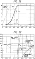
- Fig. 29 shows response characteristics with respect to a target value in the course control apparatus shown in Fig. 27.
- the abscissa indicates time; and the ordinate, a moving amount.
- a response which causes overshoot can be converted into a response which causes almost no overshoot (see a response characteristic curve C3), thus greatly improving the control characteristics.
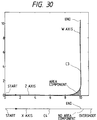
- Fig. 30 is a graph showing a physically analyzed state of the response characteristics shown in Fig. 29. Referring to Fig. 30, the abscissa indicates the virtual axis; and the ordinate, the reality axis.
- the response characteristic curve C4 in a virtual space is a target course having a line segment moving from the left to the right on the reality axis (X axis), and the response characteristic curve C3 is a target course curving at a right angle in the virtual space defined by the reality axis (X axis) and the virtual axis (W axis).
- each of weighting functions Q and X in an evaluation function includes either
- the above-described embodiment exemplifies the control system in a position control apparatus.
- the present invention can be applied to velocity control. That is, the synthetic velocity of a rotation system X axis with a high speed and coarse control precision and a rotation system Y axis with a low speed and fine control precision can be accurately controlled.
- target values are not limited to above-mentioned position and velocity, and temperature data may be used as a target value.
- the X and Y axes may be replaced with a heater having a large capacity and a heater having a small capacity, respectively, so as to perform temperature control with high precision.
- target values for moving controlled objects as reality axes and a virtual target value for moving a virtual controlled object as a virtual axis based on the reality axes are produced, and control inputs and a virtual control input which optimize a predetermined first evaluation function are calculated upon reception of the produced virtual target value, the produced target values, a virtual state amount from the virtual controlled object, state amounts from the controlled objects, the first disturbance signal for the virtual controlled object, and the second disturbance signal for the controlled objects.
- the calculated control inputs and the calculate virtual control input are respectively output to the controlled objects and the virtual controlled object, thereby minimizing the course error without changing the maximum accelerations with respect to disturbances.
- the control means calculates control inputs and a virtual control which optimize a predetermined first evaluation function upon receiving the produced virtual target value, the produced target values, a virtual state amount from the virtual controlled object, state amounts from the controlled objects, the first disturbance signal for the virtual controlled object, and the second disturbance signal for the controlled objects.
- the control means then outputs the calculated control inputs and the calculate virtual control input to the controlled objects and the virtual controlled object, respectively. With this operation, control inputs which minimize the course error without changing the maximum accelerations with respect to disturbances can be output.
- control means calculates control inputs for optimizing a predetermined second evaluation function upon receiving the target values, state amounts from the controlled objects, and disturbance signals for the controlled objects.
- the control means then outputs the control inputs to the controlled objects. With this operation control inputs for minimizing the course error can be output.
- the first and second evaluation functions include the first or second weighting function component for evaluating a course error, a follow-up operation with respect target values can be performed at a high speed without increasing the accelerations.
- the target value conversion means converts the produced target values into new target values and outputs them to the control means.
- the control means calculates control inputs for optimizing the predetermined second evaluation function upon receiving the converted target values, state amounts from the controlled objects, and disturbances acting on the controlled objects.
- the control means then outputs the control inputs to the controlled objects, thereby minimizing the course error without increasing the accelerations.
- Figs. 39 and 40 are block diagrams for explaining the arrangement of a composite system control apparatus, e.g., a position control apparatus, according to the sixth embodiment of the present invention.
- the data processing section of a control system based on a predetermined evaluation function may be constituted by a logic circuit, software (including hardware, e.g., a CPU, a ROM, and a RAM, and designed to execute various types of firmware read out from the ROM), or a combination thereof.
- a target value generation means 51 outputs a desired target value signal 52 to a target value production means 53 of a controller 65.
- the target value production means 53 produces an X axis target value 54a and a Y axis target value 54b on the basis of the input target value signal 52, and outputs the target values to adders 55a and 55b, respectively.
- the adder 55a adds the X axis target value 54a and an X axis controlled amount 60a to output an X axis error signal 56a to a compensator 57.
- the adder 55b adds the Y axis target value 54b and a Y axis controlled amount 60b to output a Y axis error signal 56b to the compensator 57.
- target value production means 53 produces the target values 54a and 54b such that the sum of the target values 54a and 54b for the respective controlled object and the desired target value signal 52 becomes equal to each other.
- the compensator 57 produces an X axis control input 58a and a Y axis control input 58b upon receiving the X axis error signal 56a, the Y axis error signal 56b, an X axis state amount 61a, and a Y axis state amount 61b.
- the compensator 57 then outputs the control inputs to controlled objects 59a and 59b, respectively.
- control systems are arranged to optimize (minimize) evaluation functions based on the following equations (6) to (8), and the compensator 57 determines control inputs which minimize a predetermined evaluation function (to be described later) in consideration of error signals associated with the respective control systems, thereby enabling control with response speed far superior to that of the prior art.
- the target value 52 for the Z axis is converted into the target value 54a for the X axis and the target value 54b for the Y axis by the target value production means 53.
- the target value 54a for the X axis the target value for the Z axis is directly used, while the target value 54b for the Y axis is set to be "0".
- the respective error signals 56a and 56b as position errors are produced from the target values 54a and 54b for the X and Y axes and the positions 60a and 60b as the X and Y controlled amounts.
- the X and Y axis control inputs 58a and 58b are produced on the basis of the error signals 56a and 56b and the X and Y axis state amounts 61a and 61b (corresponding to the velocities of the X and Y axes in the embodiment).
- equation (8) is mathematically converted from equation (7), and an equivalent relationship can be established therebetween.
- An adder 63 adds an X axis weight 62a and a Y axis weight 62b to produce and output a Z axis controlled amount 64.
- the above-mentioned control inputs 58a and 58b respectively include the sums of terms obtained by multiplying weights and errors 56 for the respective controlled objects, which errors are based on the target values 54a and 54b for the respective controlled objects, obtained from the target value 52, and the corresponding controlled amounts 60a and 60b.
- the control inputs 58a and 58b respectively include the sums of terms obtained by multiplying the state amounts 61a and 61b for the respective controlled objects by weights.
- the respective addition means adders 55a and 55b
- the compensation means calculates and outputs control inputs for the respective controlled objects, which inputs optimize the first evaluation function (equations (6) to (9) to be described later), while causing the error signals output from these addition means (adders 55a and 55b) and the controlled amounts output from the controlled objects to interfere with each other.
- the response speed with respect to controlled amounts of a composite purpose can be increased without increasing the gain of each control system.
- R is the target value vector
- X is a state vector
- U is the control input vector
- k is time
- M is the integration time
- Q and H are weighting functions.
- the same symbols in equation (7) indicate the same values as in equation (6).
- t M is the integration time.
- the present invention can be applied to the above-described method regardless of whether the control time in the evaluation function equation in the embodiment is given as a time integration form of a time interval between the current time and a finite elapsed time or a time integration form of infinite time.
- e (j) is the position error term.
- Evaluation function equations (6) to (8) include each term indicated by equation (9).
- the target value production means 53 outputs either or both of the target values 54a and 54b as "0".
- a quadratic evaluation function equation may be used as long as a weighting function of the quadratic evaluation function equation is represented by a target value function.
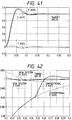
- Fig. 41 is a graph showing the control response characteristics of the composite system shown in Figs. 39 and 40. Referring to Fig. 41, the abscissa indicate time (sec); and the ordinate, a control amount.
- the controller 65 is designed to minimize the above-described evaluation functions, the X and Y axes move in phase. As a result, the Z axis approaches a target value at a high speed. At the time of convergence, the X and Y axes move in opposite phases so that the Y axis reduces the vibration of the X axis. As a result, the Z axis does not easily depart from a target value. Since the X and Y axes interfere with each other in this manner, excellent control response speed can be achieved.
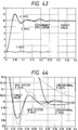
- Fig. 42 is a graph showing the convergence characteristics of the composite system with respect to target values. More specifically, Fig. 42 shows the convergence characteristics of the X and Y axes in comparison with those of the X and Y axes in the prior art.
- the maximum accelerations are 1,600 (rad/sec2) for the X axis and 188 (rad/sec2) for the Y axis, which are not much different from those in the prior art.
- the time required for the Z axis to reach 0.1% of the target value is about 20 (msec), which is shorter than that in the prior art by about 10 (msec).
- the present invention can be applied to a composite system control apparatus to which disturbances 26a and 26b are applied.
- each of the control inputs 58a and 58b input from the compensator 57 to the controlled objects 59a and 59b includes a sum U (j) of terms of inputs multiplied by weights K (j) of equation (10) (to be described later).
- the compensation means calculates control inputs for optimizing the second evaluation function (equation (10) or the like (to be described later)) and outputs them to the respective controlled objects, while causing the error signals output from the addition means (adders 55a and 55b), the controlled amounts output from the controlled objects, and either or both of the disturbances applied to the controlled objects to interfere with each other.
- the compensation means calculates control inputs for optimizing the second evaluation function (equation (10) or the like (to be described later)) and outputs them to the respective controlled objects, while causing the error signals output from the addition means (adders 55a and 55b), the controlled amounts output from the controlled objects, and either or both of the disturbances applied to the controlled objects to interfere with each other.
- the compensation means calculates and outputs control inputs for compensating the characteristics of the respective controlled objects on the basis of the integral values of error signals from the respective addition means or values obtained by multiplying the integral values by predetermined weights. Therefore, stationary errors caused by stepwise disturbances can be quickly eliminated.
- U (j) K 1(j) *e (j) + K 2(j) * ⁇ e (j) + K 3(j) *x (j) + K 4(j) *R (j)
- the sum U (j) is constituted by a term obtained by multiplying the position error term e (j) by the weight K 1(j) , a term obtained by multiplying a term, obtained by integrating the position error term e (j) , by the weight K 2(j) , a term obtained by multiplying the state amount x (j) of each axis by the weight K 3(j) , and a term obtained by multiplying the target value R (j) for each axis by the weight K 4(j) .
- the compensator 57 determines the control inputs 58a and 58b to be input to the respective controlled objects 59a and 59b upon multiplication of the weights K (j) in this manner. In this case, it is apparent that if stepwise disturbances are applied, as shown in Fig. 43, the compensator 57 outputs the control input 58a for allowing the control system for the X axis to cancel the influence of the disturbances.
- the compensator 57 outputs the control inputs 58a and 58b including terms obtained by multiplying the state amounts 61a and 61b of the respective axes by the weight K 3(j) to the controlled objects 59a and 59b. Therefore, disturbances can be converted at a very high speed, as compared with the step response characteristics of the prior art with respect to disturbances, without increasing the gain of the control system for each axis of the controller. With this operation, stationary errors caused by stepwise disturbances can be eliminated. In addition, since the two control systems interfere with each other with respect to disturbances acting on one of the systems, the influence of disturbances on target controlled amounts can be quickly eliminated.
- Fig. 44 is a graph showing the convergence characteristics with respect to target values at the time of disturbance application in the composite system control apparatus of the present invention. More specifically, Fig. 44 shows the convergence characteristics of the X and Y axes in the embodiment in comparison with those in the prior art. Note that the accelerations of the respective axes are the same.
- convergence to target values in the positioning control system can be performed within a very short period of time from the time when disturbances are applied.
- the target value production means 53 supplies the same target value as the received one to the X axis, and "0" to the Y axis in such a manner that the sum of the target values supplied to the X and Y axes becomes equal to the received target value. In this case, however, 90% of the received target value may be supplied to the X axis, while 10% of the target value may be supplied to the Y axis, so that the sum of the supplied values becomes equal to the received target value.
- the above-described embodiment exemplifies the position control apparatus, in which the control system is designed for the two axes, i.e., the X and Y axes.
- the number of axes is not limited to two.
- the present invention can be easily applied to other arrangements as long as the controller 65 can be designed to minimize an evaluation function.
- the X and Y axes as controlled objects do not interfere with each other.
- the present invention can be easily applied to a case where the controlled objects interfere with each other, as long as the controller 56 can be designed to minimize a similar evaluation function.
- control system is a position control apparatus.
- the present invention can be applied to velocity control. That is, the synthetic velocity of a rotation system X axis with a high speed and coarse control precision and a rotation system Y axis with a low speed and fine control precision can be accurately controlled.
- target values are not limited to above-mentioned position and velocity, and temperature data may be used as a target value.
- the X and Y axes may be replaced with a heater having a large capacity and a heater having a small capacity, respectively, so as to perform temperature control with high precision.
- the compensation means compensates/calculates and outputs control inputs for optimizing the first evaluation function to the respective controlled objects, while causing the error signals output from the addition means and the controlled amounts output from the controlled objects to interfere with each other.
- the response speed with respect to controlled amount of a composite purpose can be increased without increasing the gain of each control system.
- the compensation means calculates control inputs for optimizing the second evaluation function and outputs them to the respective controlled objects, while causing the error signals output from the addition means, the controlled amounts output from the controlled objects, and either or both of the disturbances applied to the controlled objects to interfere with each other. With this operation, stationary errors caused by disturbances acting on controlled amount of a composite purpose can be converged at a high speed.
- the compensation means calculates and outputs control inputs for compensating the characteristics of the respective controlled objects on the basis of the integral values of error signals from the respective addition means or values obtained by multiplying the integral values by predetermined weights. Therefore, stationary errors caused by stepwise disturbances can be quickly eliminated.
- the response characteristics with respect to the overall controlled amount as the sum of controlled amounts of the respective controlled objects of the composite system can be greatly improved, and stationary errors with respect to disturbance application can be quickly converged.
Landscapes
- Engineering & Computer Science (AREA)
- Human Computer Interaction (AREA)
- Manufacturing & Machinery (AREA)
- Physics & Mathematics (AREA)
- General Physics & Mathematics (AREA)
- Automation & Control Theory (AREA)
- Feedback Control In General (AREA)
- Control Of Position Or Direction (AREA)
Applications Claiming Priority (6)
| Application Number | Priority Date | Filing Date | Title |
|---|---|---|---|
| JP311144/92 | 1992-10-28 | ||
| JP31114492 | 1992-10-28 | ||
| JP31114392A JP3234308B2 (ja) | 1992-10-28 | 1992-10-28 | 複合制御系の制御装置および複合制御系の制御方法 |
| JP31114392 | 1992-10-28 | ||
| JP311143/92 | 1992-10-28 | ||
| JP31114492A JP3234309B2 (ja) | 1992-10-28 | 1992-10-28 | 複合系の経路制御方法およびその装置 |
Publications (3)
| Publication Number | Publication Date |
|---|---|
| EP0595604A2 true EP0595604A2 (de) | 1994-05-04 |
| EP0595604A3 EP0595604A3 (en) | 1994-06-08 |
| EP0595604B1 EP0595604B1 (de) | 2000-02-02 |
Family
ID=26566597
Family Applications (1)
| Application Number | Title | Priority Date | Filing Date |
|---|---|---|---|
| EP93308543A Expired - Lifetime EP0595604B1 (de) | 1992-10-28 | 1993-10-27 | Verfahren und Vorrichtung für ein zusammengesetztes Kurssteuerungssystem |
Country Status (4)
| Country | Link |
|---|---|
| US (1) | US5459381A (de) |
| EP (1) | EP0595604B1 (de) |
| CA (1) | CA2109363C (de) |
| DE (1) | DE69327766T2 (de) |
Families Citing this family (5)
| Publication number | Priority date | Publication date | Assignee | Title |
|---|---|---|---|---|
| US5587636A (en) * | 1995-02-24 | 1996-12-24 | Kulicke And Soffa Investments, Inc. | Observer-compensator for an electric motor system |
| DE10156781C1 (de) * | 2001-11-19 | 2003-02-27 | Siemens Ag | Aktive Kompensation von mechanischen Schwingungen und Verformungen in industriellen Bearbeitungsmaschinen |
| JP4483314B2 (ja) * | 2004-01-28 | 2010-06-16 | 株式会社安川電機 | サーボ制御装置 |
| JP4594898B2 (ja) * | 2006-04-28 | 2010-12-08 | 東芝ストレージデバイス株式会社 | ヘッド位置制御装置およびディスク装置 |
| JP5780783B2 (ja) * | 2011-03-04 | 2015-09-16 | 富士機械製造株式会社 | 干渉力補償制御装置 |
Family Cites Families (3)
| Publication number | Priority date | Publication date | Assignee | Title |
|---|---|---|---|---|
| JP2821679B2 (ja) * | 1988-07-19 | 1998-11-05 | 株式会社日立製作所 | Pwmインバータのゲート信号発生方法および装置、pwmインバータ装置 |
| JP2997036B2 (ja) * | 1990-11-30 | 2000-01-11 | 本田技研工業株式会社 | 脚式移動ロボットの歩行制御装置 |
| JP3078009B2 (ja) * | 1990-11-30 | 2000-08-21 | 本田技研工業株式会社 | 脚式移動ロボットの歩行制御装置 |
-
1993
- 1993-10-26 US US08/141,351 patent/US5459381A/en not_active Expired - Lifetime
- 1993-10-27 EP EP93308543A patent/EP0595604B1/de not_active Expired - Lifetime
- 1993-10-27 DE DE69327766T patent/DE69327766T2/de not_active Expired - Lifetime
- 1993-10-27 CA CA002109363A patent/CA2109363C/en not_active Expired - Fee Related
Non-Patent Citations (2)
| Title |
|---|
| PROCEEDINGS OF THE 1991 AMERICAN CONTROL CONFERENCE vol. 2 , 27 June 1991 , THE BOSTON PARK PLAZA,BOSTON, MASSACHUSETTS pages 1246 - 1251 XP000272030 AKIHIRO SUZUKI ET AL 'Design And Implementation Of Digital Servo Controller For High Speed Machine Tools' * |
| PROCEEDINGS OF THE 1992 AMERICAN CONTROL CONFERENCE vol. 1 , 25 June 1992 , THE WESTIN HOTEL,CHICAGO,ILLINOIS pages 370 - 374 XP000340608 CHIH-CHING LO ET AL 'Evaluation Of Servo-Controllers For Machine Tools' * |
Also Published As
| Publication number | Publication date |
|---|---|
| EP0595604B1 (de) | 2000-02-02 |
| CA2109363A1 (en) | 1994-04-29 |
| DE69327766T2 (de) | 2000-06-29 |
| US5459381A (en) | 1995-10-17 |
| CA2109363C (en) | 1997-02-25 |
| EP0595604A3 (en) | 1994-06-08 |
| DE69327766D1 (de) | 2000-03-09 |
Similar Documents
| Publication | Publication Date | Title |
|---|---|---|
| US7039494B2 (en) | Controller for machine | |
| US6587747B2 (en) | Numerically controlled curved surface machining unit | |
| EP1235126B1 (de) | Numerisches Steuerungssystem für gekrümmte Fläche | |
| US4706003A (en) | Acceleration and deceleration control system | |
| US6675061B2 (en) | Numerically controlled curved surface machining unit | |
| KR970002258B1 (ko) | 서보모터의 제어방법 | |
| EP1023973B1 (de) | Verfahren und geraet zur robotersteuerung | |
| US5988850A (en) | Curve interpolation method for performing velocity control during connecting motion of a robot | |
| Jin et al. | A fine-interpolation-based parametric interpolation method with a novel real-time look-ahead algorithm | |
| US5394323A (en) | Path error control system | |
| US5373439A (en) | Method for controlling the traveling path of a robot during acceleration and deceleration | |
| EP0595604A2 (de) | Verfahren und Vorrichtung für ein zusammengesetztes Kurssteuerungssystem | |
| US6677722B2 (en) | Servo control method | |
| JPH05111889A (ja) | 制御方式可変型ロボツト制御方式 | |
| US4968923A (en) | Servo control system | |
| EP0483756B1 (de) | Robotersteuerungsverfahren und Gerät | |
| JP3493765B2 (ja) | 産業用ロボットの制御方法とその装置 | |
| JPH03190687A (ja) | ロボットの倣い速度制御方式 | |
| JP3805476B2 (ja) | モータ制御装置 | |
| Baines et al. | Feedback linearized joint torque control of a geared, DC motor driven industrial robot | |
| JPH06138909A (ja) | 複合系の経路制御方法およびその装置 | |
| JP3068381B2 (ja) | サーボ制御装置 | |
| JP3234308B2 (ja) | 複合制御系の制御装置および複合制御系の制御方法 | |
| US4884014A (en) | Position control method | |
| JPH07327382A (ja) | 交流モータの制御方式 |
Legal Events
| Date | Code | Title | Description |
|---|---|---|---|
| PUAI | Public reference made under article 153(3) epc to a published international application that has entered the european phase |
Free format text: ORIGINAL CODE: 0009012 |
|
| PUAL | Search report despatched |
Free format text: ORIGINAL CODE: 0009013 |
|
| AK | Designated contracting states |
Kind code of ref document: A2 Designated state(s): DE FR GB NL |
|
| AK | Designated contracting states |
Kind code of ref document: A3 Designated state(s): DE FR GB NL |
|
| 17P | Request for examination filed |
Effective date: 19941021 |
|
| 17Q | First examination report despatched |
Effective date: 19951102 |
|
| GRAG | Despatch of communication of intention to grant |
Free format text: ORIGINAL CODE: EPIDOS AGRA |
|
| GRAG | Despatch of communication of intention to grant |
Free format text: ORIGINAL CODE: EPIDOS AGRA |
|
| GRAH | Despatch of communication of intention to grant a patent |
Free format text: ORIGINAL CODE: EPIDOS IGRA |
|
| GRAH | Despatch of communication of intention to grant a patent |
Free format text: ORIGINAL CODE: EPIDOS IGRA |
|
| GRAA | (expected) grant |
Free format text: ORIGINAL CODE: 0009210 |
|
| AK | Designated contracting states |
Kind code of ref document: B1 Designated state(s): DE FR GB NL |
|
| REF | Corresponds to: |
Ref document number: 69327766 Country of ref document: DE Date of ref document: 20000309 |
|
| ET | Fr: translation filed | ||
| PLBE | No opposition filed within time limit |
Free format text: ORIGINAL CODE: 0009261 |
|
| 26N | No opposition filed | ||
| REG | Reference to a national code |
Ref country code: GB Ref legal event code: IF02 |
|
| PGFP | Annual fee paid to national office [announced via postgrant information from national office to epo] |
Ref country code: NL Payment date: 20081017 Year of fee payment: 16 |
|
| PGFP | Annual fee paid to national office [announced via postgrant information from national office to epo] |
Ref country code: FR Payment date: 20081024 Year of fee payment: 16 |
|
| REG | Reference to a national code |
Ref country code: NL Ref legal event code: V1 Effective date: 20100501 |
|
| REG | Reference to a national code |
Ref country code: FR Ref legal event code: ST Effective date: 20100630 |
|
| PG25 | Lapsed in a contracting state [announced via postgrant information from national office to epo] |
Ref country code: NL Free format text: LAPSE BECAUSE OF NON-PAYMENT OF DUE FEES Effective date: 20100501 Ref country code: FR Free format text: LAPSE BECAUSE OF NON-PAYMENT OF DUE FEES Effective date: 20091102 |
|
| PGFP | Annual fee paid to national office [announced via postgrant information from national office to epo] |
Ref country code: DE Payment date: 20101031 Year of fee payment: 18 |
|
| PGFP | Annual fee paid to national office [announced via postgrant information from national office to epo] |
Ref country code: GB Payment date: 20101019 Year of fee payment: 18 |
|
| GBPC | Gb: european patent ceased through non-payment of renewal fee |
Effective date: 20121027 |
|
| PG25 | Lapsed in a contracting state [announced via postgrant information from national office to epo] |
Ref country code: DE Free format text: LAPSE BECAUSE OF NON-PAYMENT OF DUE FEES Effective date: 20130501 Ref country code: GB Free format text: LAPSE BECAUSE OF NON-PAYMENT OF DUE FEES Effective date: 20121027 |
|
| REG | Reference to a national code |
Ref country code: DE Ref legal event code: R119 Ref document number: 69327766 Country of ref document: DE Effective date: 20130501 |