EP0595417B1 - Federanordnung - Google Patents
Federanordnung Download PDFInfo
- Publication number
- EP0595417B1 EP0595417B1 EP93202969A EP93202969A EP0595417B1 EP 0595417 B1 EP0595417 B1 EP 0595417B1 EP 93202969 A EP93202969 A EP 93202969A EP 93202969 A EP93202969 A EP 93202969A EP 0595417 B1 EP0595417 B1 EP 0595417B1
- Authority
- EP
- European Patent Office
- Prior art keywords
- piston
- axial
- wall
- space
- spring device
- Prior art date
- Legal status (The legal status is an assumption and is not a legal conclusion. Google has not performed a legal analysis and makes no representation as to the accuracy of the status listed.)
- Expired - Lifetime
Links
Images


Classifications
-
- B—PERFORMING OPERATIONS; TRANSPORTING
- B21—MECHANICAL METAL-WORKING WITHOUT ESSENTIALLY REMOVING MATERIAL; PUNCHING METAL
- B21D—WORKING OR PROCESSING OF SHEET METAL OR METAL TUBES, RODS OR PROFILES WITHOUT ESSENTIALLY REMOVING MATERIAL; PUNCHING METAL
- B21D24/00—Special deep-drawing arrangements in, or in connection with, presses
- B21D24/02—Die-cushions
-
- B—PERFORMING OPERATIONS; TRANSPORTING
- B21—MECHANICAL METAL-WORKING WITHOUT ESSENTIALLY REMOVING MATERIAL; PUNCHING METAL
- B21D—WORKING OR PROCESSING OF SHEET METAL OR METAL TUBES, RODS OR PROFILES WITHOUT ESSENTIALLY REMOVING MATERIAL; PUNCHING METAL
- B21D24/00—Special deep-drawing arrangements in, or in connection with, presses
- B21D24/10—Devices controlling or operating blank holders independently, or in conjunction with dies
- B21D24/14—Devices controlling or operating blank holders independently, or in conjunction with dies pneumatically or hydraulically
Definitions
- the invention relates to a spring device comprising a first housing partly bounding a first space and a first piston which is movable in substantially sealing manner in axial direction in this first space and which is fixedly connected to a piston rod extending in axial direction which co-acts substantially sealingly with a first continuous hole in an end wall of the housing, which first piston divides the said first space into two chambers.
- Such a device embodied as a spring device is generally known (see, for example, FR-A-2 343 526).
- both chambers are filled with medium under pressure, for instance 10-100 bar.
- medium under pressure for instance 10-100 bar.
- the piston is provided with a continuous hole the same pressure prevails in both chambers.
- the piston is pressed under all conditions by the medium pressure to the side of the piston rod. Since the medium pressure and the relevant areas are constant, the spring force produced by the spring device is also constant over the whole active stroke.
- the said causes a) and b) provide a greatly increasing blank-holder pressure on the still present material for treating, which results in an undesired material deformation, damage to the material surface, breakage and an irregularly formed rim with four protrusions, so-called ears, which occur at four locations, this at 45° to the rolling direction of the material.
- the invention has for its object to provide a spring device which, during use in co-action with a deep-drawing device, is capable of causing the blank-holder pressure to decrease in proportion to the still remaining material. It is particularly the object to hold substantially constant the blank-holder force per unit of surface area on the as yet non-deformed material.
- the invention generally has for its object to embody a spring device of the said type such that it can be considered a "degressive" spring.
- a spring be it either a draw spring or compression spring, is defined by the fact that the reaction force exerted by the spring decreases as the displacement between the ends of the spring increases.
- the spring device according to the invention has the features according to claim 1.
- valve means can be linked to the action of the spring device by means of synchronization provisions.
- valve means comprise:
- This embodiment can be of very compact and simple structure and have for this purpose the feature that the first housing and the second housing are integrated and are separated by a dividing wall, that the first piston, the second piston and the piston rod are integrated and that both continuous holes are formed by one continuous hole in the dividing wall.
- Separate pressure medium feed conduits connect to the first and the second chamber. This ensures very great flexibility in the choice of the spring characteristics.
- a simple embodiment which lacks this flexibility but which is of somewhat simpler construction is characterized by a bypass conduit which connects the smallest of the said chamber parts to the other chamber.
- the spring device according to the invention can have the feature that the said conduit for free draining of medium comprises an element with adjustable passage.
- the said chamber and associated portion of the piston have in cross section a stepped, complementary structure.
- the axial surfaces of the chamber parts forming a closed contour substantially seal against the oppositely located axial surfaces of the piston which form a closed contour. In this manner a separation between the respective active chamber parts is ensured.
- some medium under pressure could already be admitted into the following chamber part or the following chamber parts. This does not have to have an adverse effect on the operation of the spring device but does mean that only limited demands need be made on the seal between the different chamber parts.
- a spring device which realizes these objectives has the feature that the axial peripheral wall of each chamber part has a small clearance relative to the corresponding axial peripheral walls of the piston.
- the simplest spring device is one having the feature that the chamber parts are bounded by surfaces extending transversely of the axial direction.
- An embodiment suitable for this purpose has the feature that the spring device has a continuous hole extending in axial direction and that the first piston co-acts in sealingly slidable manner with that hole.
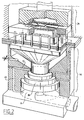
- FIG. 1 shows a degressive gas spring 1 in a first embodiment according to the invention.
- Gas spring 1 comprises a first housing 3 partly bounding a first space 2 and a first piston 5 which is movable in substantially sealing manner in axial direction 4 in this first space 2 and which is fixedly connected to a piston rod 6 which extends in axial direction and which co-acts substantially sealingly with a continuous hole 7 in an end wall 8 of housing 3, which first piston 5 divides the said first space 2 into two chambers, namely a lower chamber 9 and an upper chamber 10.
- a first feed conduit for medium under pressure connects onto the lower chamber 9.
- a second feed conduit 12 for medium under pressure connects onto the upper chamber.
- the upper chamber 10 is embodied as three chamber parts 13, 14, 15 respectively forming a closed contour, mutually connecting in step-like manner and each having an axial peripheral wall 16, 17, 18 respectively, which chamber parts 13, 14, 15 are axially bounded by successive transverse wall portions 19, 20, 21 respectively (which in this embodiment are oriented perpendicularly of the axial direction 4) with increasing surface areas, wherein the successive axial peripheral walls 16, 17, 18 have increasing axial lengths.
- the first piston 5 has a corresponding form.
- the feed conduit 12 debouches on wall portion 19, that is, the wall portion which adjoins the piston rod 6 and has the smallest surface area.
- Medium drain conduits 22, 23 connect onto the respective wall portions 20 and 21. These debouch into a second space 24 which is bounded by a second housing 25 formed integrally with the first housing 3 and having a general cup shape.
- a second piston 26 is slidable substantially, in any case more or less, sealingly in the second space 24.
- the second piston 26 is carried by the piston rod 6. Connecting onto the second space 24 is a conduit for free draining of medium out of the second space 24.
- the medium drain conduits 22 and 23 debouch into the second space 24 at relative positions in accordance with the mutual differences between the axial lengths of the said axial peripheral walls 16, 17 and 17, 18.
- the second piston 26 has an axial length, that is, a length along which it co-acts sealingly with the edge of the second space 24, such that in the one extreme position in which the upper chamber 10 has its smallest volume it unblocks both medium drain conduits 22, 23 and in the other extreme position in which the upper chamber 10 has its largest volume it blocks both medium drain conduits 22, 23.
- An element 28 with adjustable passage is arranged in the conduit 27.
- peripheral walls 16, 17, 18 have a small clearance relative to the corresponding axial peripheral walls of the piston.
- the second housing 25 supports a deep-drawing device 29.
- a metal plate 30 is inserted between the edges of two mould parts 31, 32.
- Mould part 31 has a continuous hole 34 for passage of a third mould part 33 which has a form corresponding with the desired form of a deep-drawn plate.
- the second mould part 32 has a correspondingly formed cavity 35.
- Through relative displacement of mould parts 32 and 33 the metal plate 30 clamped between mould parts 31 and 32 is pressed against the bottom of the mould cavity 35 by the mould part 33.
- a relatively downward directed force is exerted on mould part 32 which is transferred via force transmitting pins 36 (which extend through a dividing wall 37) onto the second piston 26, whereby the first piston 5 of gas spring 1 is pressed downward.
- the speed at which gas spring 1 is reset can be adjusted in accordance with the wishes of the user.
- the pressure in the second space 24 must again be atmospheric.
- the spring characteristic realized is dependent on the dimensioning of the gas spring and the pressure of the medium fed via the conduits 11 and 12. It has been found in practice that practically any desired degressive characteristic can be realized with a sufficient degree of accuracy and reproducibility.
- Fig. 2 shows a gas spring 44 with the deep-drawing device 29.
- the structure of gas spring 44 differs from the embodiment of fig. 1 only in the presence of bypass conduit 45 which connects the lower chamber 9 to the upper chamber 10.
- bypass conduit 45 which connects the lower chamber 9 to the upper chamber 10.
- the same medium pressure hereby always prevails in these two chambers 9, 10. This limits the adjustability of the spring characteristic.
- Fig. 3 and 4 show a gas spring 46 in two positions.
- elements corresponding functionally with the elements of fig. 1 and 2 are designated with the same reference numerals as in the discussion of fig. 1 and 2.
- Fig. 3 shows clearly that in the situation where the chamber part 13 is active and the chamber part 14 is on the point of becoming active, the debouchment of the medium drain conduit 22 into the second space 24 is on the point of being closed by the piston 26.
- Fig. 4 shows that in the position wherein, after chamber part 14, chamber part 15 also becomes active, the debouchment of the medium drain conduit 23 into the second space 24 is also blocked by the piston 26.
- Fig. 5 shows a gas spring 47 in which the upper chamber 10 consists of four chamber parts, namely the chamber parts 13, 14, 15 in accordance with the above described embodiments having thereby an additional chamber part 48. This debouches via a medium drain conduit 49 into the second space 24 below the debouchment of the medium drain conduit 23.
- first piston 5 co-acts sealingly with the first housing 3 via a sealing ring 50.
- the piston rod 6 is also guided sealingly in the continuous hole 7 by a sealing ring 51.
- Fig. 6 shows a gas spring 55 with a central continuous hole 56.
- the first piston 57 is sealingly slidable relative to this hole.
- Use is made for this purpose of a bottom part 58 with a central cylinder 59, which cylinder 59 co-acts with the first piston 57 by means of a sealing ring 60.
- the gas spring 55 corresponds substantially with the gas spring 44 according to fig. 2. It is however important to note that there are a number of differences which make it desirable to discuss this important embodiment.
- the bypass conduit 45 shown in fig. 2 is implemented in this embodiment as a free space serving as a conduit.
- the second feed conduit 12 debouches on the peripheral wall 16 of the first chamber part 13.
- the gas spring 55 hereby acts in the first part of the stroke, in which the piston 57 still fully closes off the debouchment of conduit 12, as a normal gas spring. Only after the conduit 12 has been partially unblocked does the degressive action according to the invention take place.
- Fig. 7 shows a detail of a variant in which the second feed conduit 12 debouches into the chamber part 13 in the transition zone between the flat transverse wall portion 19 and the peripheral wall 16.
- Fig. 8 shows a comparison between three known springs and the degressive spring device according to the invention.
- Fig. 8a shows a spring provided with a rubber block 52 with the associated spring characteristic. Shown vertically is the force, horizontally the compression of the spring. It is assumed in the characteristic that the spring has a certain bias.
- Fig. 8b shows a normal spiral spring 53 with associated characteristic.
- the rubber block spring and the spiral spring have in common that the spring characteristics display a progressive nature.
- Fig. 8c shows a typical gas spring 54. It can be seen from the spring characteristic that the compression force is substantially constant.
- Fig. 8d shows schematically the gas spring 1 according to the invention. It can be seen from the accompanying characteristic that practically any spring characteristic can be realized inside the hatched section by suitable choice of the gas pressures in combination with the design of the dimensioning of the gas spring.
- Fig. 9 shows a hydraulic spring device 61 of the degressive type.
- the above discussed figures 1-7 all related to degressive spring devices based on the use of gas under pressure as medium.
- the spring device 61 is based on a liquid as medium. Since a liquid is non-compressible, means are necessary, otherwise than in the use of gas, to ensure that, as the pressure builds up, the liquid can escape where necessary in order to enable relative movement of the piston and the cylinder, while on the other hand means must also be present to build up and maintain this pressure, and particularly to hold it substantially constant during a work cycle.
- the structure of the device 61 corresponds by and large with that as according to fig. 1. It will therefore suffice to discuss a number of components which do not appear in fig. 1.
- a hydraulic system depicted in the form of a block diagram is connected to the cylinder-piston unit 62. Situated in a reservoir 63 is a liquid medium such as hydraulic oil.
- a pump 64 driven by a motor 65 brings the hydraulic oil to the pressure required for operation of the unit 62.
- the oil under pressure is supplied via a pressure regulator-regulating valve 66 to an inlet 67 of the unit 62. Monitoring of the pressure is carried out by a meter 68.
- the oil thus brought under pressure can act to exert pressure on the upper part of piston 69, analogously to the foregoing discussion of the gas springs.
- For return of the oil to the reservoir 63 during upward directed movement of piston 69 use is made of four conduits which are grouped as manifold and therefore designated jointly with the reference numeral 70.
- An insert piece 76 partly bounding the cylinder jacket-like space 73 limits the volume of the space 63, whereby the quantity of oil for displacement can remain comparatively limited, so that at higher speeds the danger of cavitations is prevented and the mass of oil to be displaced remains limited.
- the outlet of pump 64 is also connected to a known pressure storage reservoir 79, a pressure gauge 80 and an adjustable tap 81 which in turn is connected to a pressure gauge 82, a second pressure reservoir 83 and a connection 84 on the underside of the cylinder/piston unit 62.
- reservoir 83 Situated in reservoir 83 is an up and downward movable piston or a membrane 85 which is adjustably biased by nitrogen under pressure designated with the reference numeral 86.
- the valve 81 is closed. Should leakage occur somewhere in the system, whereby pressure loss or a shortage of oil occurs, the valve 81 is opened and oil under pressure is admitted into the system as required.
Landscapes
- Engineering & Computer Science (AREA)
- Mechanical Engineering (AREA)
- Fluid-Damping Devices (AREA)
- Springs (AREA)
- Finger-Pressure Massage (AREA)
- Glass Compositions (AREA)
- Actuator (AREA)
- Transmission Of Braking Force In Braking Systems (AREA)
Claims (8)
- Federvorrichtung mit einem ersten Gehäuse (3), das teilweise einen ersten Raum (2) abgrenzt, und einem ersten Kolben (5), der in im wesentlichen dichter Weise in der Axialrichtung (4) in diesem Raum (2) verschiebbar ist und der fest mit einer Kolbenstange (6) verbunden ist, die sich in der Axialrichtung erstreckt und im wesentlichen dicht mit einem ersten Durchgangsloch (7) in einer Endwand (8) des Gehäuses (3) zusammenwirkt, wobei der erste Kolben (5) den ersten Raum (2) in zwei Kammern (9, 10) unterteilt,
dadurch gekennzeichnet,
daß eine erste und eine zweite Zuführleitung (11, 12) zur Zuführung eines Mediums unter Druck vorgesehen sind, die mit der jeweiligen Kammer (9, 10) verbunden sind,
daß wenigstens eine der Kammern (10) durch mehrere Kammerabschnitte (13-15) gebildet ist, die eine geschlossene Kontur bilden, miteinander stufenförmig verbunden sind und jeweils eine axiale Randwand (16-18) aufweisen, wobei die Kammerabschnitte (13-15) axial durch aufeinanderfolgende Querwände (19-21) mit in der von dem Loch abgewandten Richtung ansteigenden Außendurchmesser, und durch aufeinanderfolgende axiale Randwände (16-18) mit ansteigenden Axiallängen begrenzt sind, wobei der erste Kolben (5) eine korrespondierende Form aufweist und die zweite Zuführleitung (12) in den Kammerabschnitt (13) mit der kleinsten Querschnittfläche der Querwand (19) in der Nähe dieser Querwand (19) an der axialen Randwand (13) oder in dem Übergangsbereich zwischen der Querwand (19) und der axialen Randwand (13) mündet, und für jeden weiteren Kammerabschnitt (14, 15) eine Medium-Ablaßleitung (22, 23) in die jeweilige Querwand (20, 22), in der Nähe dieser Querwand (20, 21) an der axialen Randwand (14, 15) oder in dem Übergangsbereich zwischen der Querwand (20, 21) und der axialen Randwand (14, 15) mündet, und
eine Ventileinrichtung (26) vorgesehen ist, die die jeweilige Medium-Ablaßleitung (22, 23) nur in einer Position frei gibt, in der die Verbindung zwischen dem jeweiligen Kammerabschnitt (20, 21) und dem angrenzenden Kammerabschnitt vollständig oder im wesentlichen vollständig durch den ersten Kolben (5) verschlossen ist. - Federvorrichtung nach Anspruch 1,
dadurch gekennzeichnet,
daß die Ventileinrichtung aufweist:ein tassenförmiges zweites Gehäuse (25), das teilweise einen Zweiten Raum (24) abgrenzt und fest mit dem ersten Gehäuse (3) verbunden ist, und einen zweiten Kolben (26), der in im wesentlichen dichter Weise in diesen zweiten Raum (24) verschiebbar ist und der fest mit der Kolbenstange (6) verbunden ist, die in dichter Weise mit einem zweiten Durchgangsloch in einer Wand des zweiten Gehäuses (25) zusammenwirkt, wobei der zweite Raum (24) mit einer Leitung zum freien Ablaß eines Mediums verbunden ist,die jeweiligen Ablaßleitungen im zweiten Raum an Relativpositionen entsprechend dem jeweiligen Unterschied zwischen den axialen Längen der axialen Randwände angeordnet sind, undder zweite Kolben (26) eine axiale Länge derart aufweist, daß er in einer Endposition, in der die eine der beiden Kammern (9, 10) ihr geringstes Volumen aufweist, alle Ablaßleitungen freigibt, und in der anderen Endposition, in der die eine der beiden Kammern (19, 15) ihr größtes Volumen aufweist, sämtliche Ablaßleitungen verschließt. - Federvorrichtung nach Anspruch 2,
dadurch gekennzeichnet,
daß das erste Gehäuse (3) und das zweite Gehäuse (25) einstückig ausgebildet sind und durch eine Trennwand (8) unterteilt werden, daß der erste Kolben (5), der zweite Kolben (26) und die Kolbenstange (6) einstückig ausgebildet sind, und daß die beiden Durchgangslöcher durch ein Durchgangsloch in der Trennwand (8) gebildet werden. - Federvorrichtung nach Anspruch 1, gekennzeichnet durch eine Bypaßleitung (45), die den kleinsten der Kammerabschnitte (13) mit der anderen Kammer (9) verbindet.
- Federvorrichtung nach Anspruch 2,
dadurch gekennzeichnet,
daß die Leitung zum freien Ablaß des Mediums (27) ein Element (28) mit einstellbarem Durchlaß aufweist. - Federvorrichtung nach Anspruch 1,
dadurch gekennzeichnet,
daß die axiale Randwand (16-18) von jedem Kammerabschnitt (13-15) ein kleines Spiel bezüglich den entsprechenden axialen Randwänden des ersten Kolbens (5) aufweist. - Federvorrichtung nach Anspruch 1,
dadurch gekennzeichnet,
daß die Kammerabschnitte (13-15) durch Flächen begrenzt sind, die sich quer zu der Axialrichtung erstrecken. - Federvorrichtung nach Anspruch 1,
dadurch gekennzeichnet,
daß die Federvorrichtung ein Durchgangsloch (7) aufweist, das sich in der Axialrichtung erstreckt, und daß der erste Kolben (5) in abgedichtet verschiebbarer Weise mit diesem Loch (7) zusammenwirkt.
Applications Claiming Priority (2)
| Application Number | Priority Date | Filing Date | Title |
|---|---|---|---|
| NL9201857A NL9201857A (nl) | 1992-10-26 | 1992-10-26 | Degressieve gasveer. |
| NL9201857 | 1992-10-26 |
Publications (2)
| Publication Number | Publication Date |
|---|---|
| EP0595417A1 EP0595417A1 (de) | 1994-05-04 |
| EP0595417B1 true EP0595417B1 (de) | 1997-06-18 |
Family
ID=19861427
Family Applications (1)
| Application Number | Title | Priority Date | Filing Date |
|---|---|---|---|
| EP93202969A Expired - Lifetime EP0595417B1 (de) | 1992-10-26 | 1993-10-22 | Federanordnung |
Country Status (10)
| Country | Link |
|---|---|
| US (1) | US5454549A (de) |
| EP (1) | EP0595417B1 (de) |
| JP (1) | JP3816963B2 (de) |
| KR (1) | KR0164439B1 (de) |
| AT (1) | ATE154530T1 (de) |
| CA (1) | CA2109137C (de) |
| DE (1) | DE69311672T2 (de) |
| ES (1) | ES2107613T3 (de) |
| NL (1) | NL9201857A (de) |
| TW (1) | TW227595B (de) |
Cited By (1)
| Publication number | Priority date | Publication date | Assignee | Title |
|---|---|---|---|---|
| DE102007005011A1 (de) | 2007-02-01 | 2008-08-14 | Saeta Gmbh & Co. Kg | Verfahren und Vorrichtung zum Tiefziehen von Rohlingen aus Blechmaterial zu flanschlosen Formlingen |
Families Citing this family (2)
| Publication number | Priority date | Publication date | Assignee | Title |
|---|---|---|---|---|
| DE19800661B4 (de) * | 1998-01-10 | 2005-05-19 | Burkhard Oest | Gasdruckfeder mit regelbarem Gasvolumen |
| US7152451B1 (en) * | 2006-05-26 | 2006-12-26 | Diebolt International, Inc. | Reaction device for forming equipment |
Family Cites Families (9)
| Publication number | Priority date | Publication date | Assignee | Title |
|---|---|---|---|---|
| US1967245A (en) * | 1931-02-20 | 1934-07-24 | American Can Co | Art of drawing |
| US2143429A (en) * | 1936-10-14 | 1939-01-10 | Frank Tea & Spice Company | Apparatus for forming sheet metal forms |
| US3267715A (en) * | 1961-10-16 | 1966-08-23 | Dro Engineering Company Di | Hydraulic control for dies in ram type presses |
| US3420089A (en) * | 1966-02-16 | 1969-01-07 | Mc Donnell Douglas Corp | Variable pressure drawpress and method |
| DE2609916A1 (de) * | 1976-03-10 | 1977-09-15 | Etscheid Ohg Hermann | Niederhaltevorrichtung an einer tiefziehpresse |
| GB1481202A (en) * | 1976-03-29 | 1977-07-27 | Metal Box Co Ltd | Deep drawing |
| US4745792A (en) * | 1986-10-14 | 1988-05-24 | Aluminum Company Of America | Blankholder for a draw press |
| US4796454A (en) * | 1987-02-09 | 1989-01-10 | Redicon Corporation | Method for controlling movement in a single action forming press |
| US4873859A (en) * | 1987-02-09 | 1989-10-17 | Redicon Corporation | Apparatus for controlling movement in a single action forming press |
-
1992
- 1992-10-26 NL NL9201857A patent/NL9201857A/nl not_active Application Discontinuation
-
1993
- 1993-10-20 TW TW082108728A patent/TW227595B/zh active
- 1993-10-22 ES ES93202969T patent/ES2107613T3/es not_active Expired - Lifetime
- 1993-10-22 AT AT93202969T patent/ATE154530T1/de not_active IP Right Cessation
- 1993-10-22 EP EP93202969A patent/EP0595417B1/de not_active Expired - Lifetime
- 1993-10-22 DE DE69311672T patent/DE69311672T2/de not_active Expired - Fee Related
- 1993-10-25 JP JP26624493A patent/JP3816963B2/ja not_active Expired - Lifetime
- 1993-10-25 CA CA002109137A patent/CA2109137C/en not_active Expired - Fee Related
- 1993-10-26 US US08/143,566 patent/US5454549A/en not_active Expired - Fee Related
- 1993-10-26 KR KR1019930022268A patent/KR0164439B1/ko not_active Expired - Fee Related
Cited By (1)
| Publication number | Priority date | Publication date | Assignee | Title |
|---|---|---|---|---|
| DE102007005011A1 (de) | 2007-02-01 | 2008-08-14 | Saeta Gmbh & Co. Kg | Verfahren und Vorrichtung zum Tiefziehen von Rohlingen aus Blechmaterial zu flanschlosen Formlingen |
Also Published As
| Publication number | Publication date |
|---|---|
| US5454549A (en) | 1995-10-03 |
| JP3816963B2 (ja) | 2006-08-30 |
| CA2109137A1 (en) | 1994-04-27 |
| JPH06241258A (ja) | 1994-08-30 |
| KR940008806A (ko) | 1994-05-16 |
| CA2109137C (en) | 1999-07-27 |
| KR0164439B1 (ko) | 1999-01-15 |
| TW227595B (de) | 1994-08-01 |
| NL9201857A (nl) | 1993-10-18 |
| DE69311672T2 (de) | 1998-01-08 |
| DE69311672D1 (de) | 1997-07-24 |
| ES2107613T3 (es) | 1997-12-01 |
| EP0595417A1 (de) | 1994-05-04 |
| ATE154530T1 (de) | 1997-07-15 |
Similar Documents
| Publication | Publication Date | Title |
|---|---|---|
| CA1280039C (en) | Drawing installation for a press | |
| US4229965A (en) | Hydraulic circuit of a hydromechanical drawing press | |
| US20110099995A1 (en) | Piston pump of a hydraulic vehicle brake system | |
| CA1052234A (en) | Two step pressure intensifier system | |
| WO1989002793A1 (en) | Power press with improved cushioning system | |
| US5810567A (en) | Hydraulic Diaphragm pump | |
| JPH06179100A (ja) | プレス組立体に使用するシール装置 | |
| EP0595417B1 (de) | Federanordnung | |
| US5609343A (en) | Sealing rings for spool valves | |
| JPH0769196A (ja) | 調節可能な圧力制御装置とその製造方法 | |
| US8057198B2 (en) | Variable displacement piezo-electric pumps | |
| US5727440A (en) | Gas cylinder element | |
| JPH0777163A (ja) | ダイヤフラムポンプ | |
| US3739807A (en) | Valving arrangement | |
| US5613396A (en) | Index-feed machining system | |
| US5195349A (en) | Forming machine and process for forming material therewith | |
| US4457498A (en) | Force balanced die cylinders | |
| EP0273721A2 (de) | Druckverstärker für eine Presse | |
| EP0543177B1 (de) | Hydraulischer Stellantrieb | |
| GB2201735A (en) | A control system for a rotary compressor | |
| US2507194A (en) | Shape-forming device | |
| US3046923A (en) | Hydraulic stamping press with a die made of resilient material | |
| US3613710A (en) | Switchover valve for pneumatic installations | |
| US3252698A (en) | Hydraulic cushion and return device for dies | |
| JP3657503B2 (ja) | 均圧用シリンダ装置およびその均圧用シリンダ装置の組付方法 |
Legal Events
| Date | Code | Title | Description |
|---|---|---|---|
| PUAI | Public reference made under article 153(3) epc to a published international application that has entered the european phase |
Free format text: ORIGINAL CODE: 0009012 |
|
| AK | Designated contracting states |
Kind code of ref document: A1 Designated state(s): AT BE CH DE DK ES FR GB GR IE IT LI LU MC NL PT SE |
|
| 17P | Request for examination filed |
Effective date: 19940517 |
|
| GRAG | Despatch of communication of intention to grant |
Free format text: ORIGINAL CODE: EPIDOS AGRA |
|
| 17Q | First examination report despatched |
Effective date: 19960507 |
|
| GRAH | Despatch of communication of intention to grant a patent |
Free format text: ORIGINAL CODE: EPIDOS IGRA |
|
| GRAH | Despatch of communication of intention to grant a patent |
Free format text: ORIGINAL CODE: EPIDOS IGRA |
|
| GRAA | (expected) grant |
Free format text: ORIGINAL CODE: 0009210 |
|
| AK | Designated contracting states |
Kind code of ref document: B1 Designated state(s): AT BE CH DE DK ES FR GB GR IE IT LI LU MC NL PT SE |
|
| PG25 | Lapsed in a contracting state [announced via postgrant information from national office to epo] |
Ref country code: GR Free format text: LAPSE BECAUSE OF FAILURE TO SUBMIT A TRANSLATION OF THE DESCRIPTION OR TO PAY THE FEE WITHIN THE PRESCRIBED TIME-LIMIT Effective date: 19970618 Ref country code: DK Effective date: 19970618 |
|
| REF | Corresponds to: |
Ref document number: 154530 Country of ref document: AT Date of ref document: 19970715 Kind code of ref document: T |
|
| REG | Reference to a national code |
Ref country code: CH Ref legal event code: EP |
|
| REF | Corresponds to: |
Ref document number: 69311672 Country of ref document: DE Date of ref document: 19970724 |
|
| ITF | It: translation for a ep patent filed | ||
| PG25 | Lapsed in a contracting state [announced via postgrant information from national office to epo] |
Ref country code: PT Effective date: 19970918 |
|
| ET | Fr: translation filed | ||
| PG25 | Lapsed in a contracting state [announced via postgrant information from national office to epo] |
Ref country code: LU Free format text: LAPSE BECAUSE OF NON-PAYMENT OF DUE FEES Effective date: 19971031 |
|
| REG | Reference to a national code |
Ref country code: ES Ref legal event code: FG2A Ref document number: 2107613 Country of ref document: ES Kind code of ref document: T3 |
|
| REG | Reference to a national code |
Ref country code: CH Ref legal event code: NV Representative=s name: ARNOLD & SIEDSMA AG |
|
| PLBE | No opposition filed within time limit |
Free format text: ORIGINAL CODE: 0009261 |
|
| PG25 | Lapsed in a contracting state [announced via postgrant information from national office to epo] |
Ref country code: MC Free format text: LAPSE BECAUSE OF NON-PAYMENT OF DUE FEES Effective date: 19980430 |
|
| 26N | No opposition filed | ||
| PGFP | Annual fee paid to national office [announced via postgrant information from national office to epo] |
Ref country code: AT Payment date: 20001109 Year of fee payment: 8 |
|
| PGFP | Annual fee paid to national office [announced via postgrant information from national office to epo] |
Ref country code: FR Payment date: 20001113 Year of fee payment: 8 |
|
| PGFP | Annual fee paid to national office [announced via postgrant information from national office to epo] |
Ref country code: IE Payment date: 20001117 Year of fee payment: 8 Ref country code: CH Payment date: 20001117 Year of fee payment: 8 |
|
| PGFP | Annual fee paid to national office [announced via postgrant information from national office to epo] |
Ref country code: SE Payment date: 20001120 Year of fee payment: 8 Ref country code: GB Payment date: 20001120 Year of fee payment: 8 |
|
| PGFP | Annual fee paid to national office [announced via postgrant information from national office to epo] |
Ref country code: NL Payment date: 20001123 Year of fee payment: 8 |
|
| PGFP | Annual fee paid to national office [announced via postgrant information from national office to epo] |
Ref country code: ES Payment date: 20001130 Year of fee payment: 8 |
|
| PGFP | Annual fee paid to national office [announced via postgrant information from national office to epo] |
Ref country code: BE Payment date: 20001218 Year of fee payment: 8 |
|
| PG25 | Lapsed in a contracting state [announced via postgrant information from national office to epo] |
Ref country code: IE Free format text: LAPSE BECAUSE OF FAILURE TO SUBMIT A TRANSLATION OF THE DESCRIPTION OR TO PAY THE FEE WITHIN THE PRESCRIBED TIME-LIMIT Effective date: 20011022 Ref country code: GB Free format text: LAPSE BECAUSE OF NON-PAYMENT OF DUE FEES Effective date: 20011022 Ref country code: AT Free format text: LAPSE BECAUSE OF NON-PAYMENT OF DUE FEES Effective date: 20011022 |
|
| PG25 | Lapsed in a contracting state [announced via postgrant information from national office to epo] |
Ref country code: SE Free format text: LAPSE BECAUSE OF NON-PAYMENT OF DUE FEES Effective date: 20011023 Ref country code: ES Free format text: LAPSE BECAUSE OF NON-PAYMENT OF DUE FEES Effective date: 20011023 |
|
| PG25 | Lapsed in a contracting state [announced via postgrant information from national office to epo] |
Ref country code: LI Free format text: LAPSE BECAUSE OF NON-PAYMENT OF DUE FEES Effective date: 20011031 Ref country code: CH Free format text: LAPSE BECAUSE OF NON-PAYMENT OF DUE FEES Effective date: 20011031 Ref country code: BE Free format text: LAPSE BECAUSE OF NON-PAYMENT OF DUE FEES Effective date: 20011031 |
|
| REG | Reference to a national code |
Ref country code: GB Ref legal event code: IF02 |
|
| BERE | Be: lapsed |
Owner name: KAMPFER HANS-PETER Effective date: 20011031 |
|
| PG25 | Lapsed in a contracting state [announced via postgrant information from national office to epo] |
Ref country code: NL Free format text: LAPSE BECAUSE OF NON-PAYMENT OF DUE FEES Effective date: 20020501 |
|
| EUG | Se: european patent has lapsed |
Ref document number: 93202969.7 |
|
| GBPC | Gb: european patent ceased through non-payment of renewal fee |
Effective date: 20011022 |
|
| REG | Reference to a national code |
Ref country code: CH Ref legal event code: PL |
|
| PG25 | Lapsed in a contracting state [announced via postgrant information from national office to epo] |
Ref country code: FR Free format text: LAPSE BECAUSE OF NON-PAYMENT OF DUE FEES Effective date: 20020628 |
|
| NLV4 | Nl: lapsed or anulled due to non-payment of the annual fee |
Effective date: 20020501 |
|
| REG | Reference to a national code |
Ref country code: IE Ref legal event code: MM4A |
|
| REG | Reference to a national code |
Ref country code: FR Ref legal event code: ST |
|
| REG | Reference to a national code |
Ref country code: ES Ref legal event code: FD2A Effective date: 20021113 |
|
| PG25 | Lapsed in a contracting state [announced via postgrant information from national office to epo] |
Ref country code: IT Free format text: LAPSE BECAUSE OF NON-PAYMENT OF DUE FEES Effective date: 20051022 |
|
| PGFP | Annual fee paid to national office [announced via postgrant information from national office to epo] |
Ref country code: DE Payment date: 20071213 Year of fee payment: 15 |
|
| PG25 | Lapsed in a contracting state [announced via postgrant information from national office to epo] |
Ref country code: DE Free format text: LAPSE BECAUSE OF NON-PAYMENT OF DUE FEES Effective date: 20090501 |