EP0595112B1 - Schnecke für Zweiwellenextruder und Zweiwellenextruder - Google Patents
Schnecke für Zweiwellenextruder und Zweiwellenextruder Download PDFInfo
- Publication number
- EP0595112B1 EP0595112B1 EP93116543A EP93116543A EP0595112B1 EP 0595112 B1 EP0595112 B1 EP 0595112B1 EP 93116543 A EP93116543 A EP 93116543A EP 93116543 A EP93116543 A EP 93116543A EP 0595112 B1 EP0595112 B1 EP 0595112B1
- Authority
- EP
- European Patent Office
- Prior art keywords
- shaft
- distal end
- double
- screw
- extruding device
- Prior art date
- Legal status (The legal status is an assumption and is not a legal conclusion. Google has not performed a legal analysis and makes no representation as to the accuracy of the status listed.)
- Expired - Lifetime
Links
Images


Classifications
-
- B—PERFORMING OPERATIONS; TRANSPORTING
- B29—WORKING OF PLASTICS; WORKING OF SUBSTANCES IN A PLASTIC STATE IN GENERAL
- B29C—SHAPING OR JOINING OF PLASTICS; SHAPING OF MATERIAL IN A PLASTIC STATE, NOT OTHERWISE PROVIDED FOR; AFTER-TREATMENT OF THE SHAPED PRODUCTS, e.g. REPAIRING
- B29C48/00—Extrusion moulding, i.e. expressing the moulding material through a die or nozzle which imparts the desired form; Apparatus therefor
- B29C48/25—Component parts, details or accessories; Auxiliary operations
- B29C48/30—Extrusion nozzles or dies
- B29C48/35—Extrusion nozzles or dies with rollers
-
- B—PERFORMING OPERATIONS; TRANSPORTING
- B29—WORKING OF PLASTICS; WORKING OF SUBSTANCES IN A PLASTIC STATE IN GENERAL
- B29B—PREPARATION OR PRETREATMENT OF THE MATERIAL TO BE SHAPED; MAKING GRANULES OR PREFORMS; RECOVERY OF PLASTICS OR OTHER CONSTITUENTS OF WASTE MATERIAL CONTAINING PLASTICS
- B29B7/00—Mixing; Kneading
- B29B7/30—Mixing; Kneading continuous, with mechanical mixing or kneading devices
- B29B7/34—Mixing; Kneading continuous, with mechanical mixing or kneading devices with movable mixing or kneading devices
- B29B7/38—Mixing; Kneading continuous, with mechanical mixing or kneading devices with movable mixing or kneading devices rotary
- B29B7/46—Mixing; Kneading continuous, with mechanical mixing or kneading devices with movable mixing or kneading devices rotary with more than one shaft
- B29B7/48—Mixing; Kneading continuous, with mechanical mixing or kneading devices with movable mixing or kneading devices rotary with more than one shaft with intermeshing devices, e.g. screws
-
- B—PERFORMING OPERATIONS; TRANSPORTING
- B29—WORKING OF PLASTICS; WORKING OF SUBSTANCES IN A PLASTIC STATE IN GENERAL
- B29B—PREPARATION OR PRETREATMENT OF THE MATERIAL TO BE SHAPED; MAKING GRANULES OR PREFORMS; RECOVERY OF PLASTICS OR OTHER CONSTITUENTS OF WASTE MATERIAL CONTAINING PLASTICS
- B29B7/00—Mixing; Kneading
- B29B7/30—Mixing; Kneading continuous, with mechanical mixing or kneading devices
- B29B7/34—Mixing; Kneading continuous, with mechanical mixing or kneading devices with movable mixing or kneading devices
- B29B7/52—Mixing; Kneading continuous, with mechanical mixing or kneading devices with movable mixing or kneading devices with rollers or the like, e.g. calenders
-
- B—PERFORMING OPERATIONS; TRANSPORTING
- B29—WORKING OF PLASTICS; WORKING OF SUBSTANCES IN A PLASTIC STATE IN GENERAL
- B29B—PREPARATION OR PRETREATMENT OF THE MATERIAL TO BE SHAPED; MAKING GRANULES OR PREFORMS; RECOVERY OF PLASTICS OR OTHER CONSTITUENTS OF WASTE MATERIAL CONTAINING PLASTICS
- B29B7/00—Mixing; Kneading
- B29B7/30—Mixing; Kneading continuous, with mechanical mixing or kneading devices
- B29B7/58—Component parts, details or accessories; Auxiliary operations
- B29B7/60—Component parts, details or accessories; Auxiliary operations for feeding, e.g. end guides for the incoming material
-
- B—PERFORMING OPERATIONS; TRANSPORTING
- B29—WORKING OF PLASTICS; WORKING OF SUBSTANCES IN A PLASTIC STATE IN GENERAL
- B29B—PREPARATION OR PRETREATMENT OF THE MATERIAL TO BE SHAPED; MAKING GRANULES OR PREFORMS; RECOVERY OF PLASTICS OR OTHER CONSTITUENTS OF WASTE MATERIAL CONTAINING PLASTICS
- B29B7/00—Mixing; Kneading
- B29B7/74—Mixing; Kneading using other mixers or combinations of mixers, e.g. of dissimilar mixers ; Plant
- B29B7/7476—Systems, i.e. flow charts or diagrams; Plants
- B29B7/7495—Systems, i.e. flow charts or diagrams; Plants for mixing rubber
-
- B—PERFORMING OPERATIONS; TRANSPORTING
- B29—WORKING OF PLASTICS; WORKING OF SUBSTANCES IN A PLASTIC STATE IN GENERAL
- B29C—SHAPING OR JOINING OF PLASTICS; SHAPING OF MATERIAL IN A PLASTIC STATE, NOT OTHERWISE PROVIDED FOR; AFTER-TREATMENT OF THE SHAPED PRODUCTS, e.g. REPAIRING
- B29C48/00—Extrusion moulding, i.e. expressing the moulding material through a die or nozzle which imparts the desired form; Apparatus therefor
- B29C48/03—Extrusion moulding, i.e. expressing the moulding material through a die or nozzle which imparts the desired form; Apparatus therefor characterised by the shape of the extruded material at extrusion
- B29C48/07—Flat, e.g. panels
-
- B—PERFORMING OPERATIONS; TRANSPORTING
- B29—WORKING OF PLASTICS; WORKING OF SUBSTANCES IN A PLASTIC STATE IN GENERAL
- B29C—SHAPING OR JOINING OF PLASTICS; SHAPING OF MATERIAL IN A PLASTIC STATE, NOT OTHERWISE PROVIDED FOR; AFTER-TREATMENT OF THE SHAPED PRODUCTS, e.g. REPAIRING
- B29C48/00—Extrusion moulding, i.e. expressing the moulding material through a die or nozzle which imparts the desired form; Apparatus therefor
- B29C48/25—Component parts, details or accessories; Auxiliary operations
- B29C48/36—Means for plasticising or homogenising the moulding material or forcing it through the nozzle or die
- B29C48/395—Means for plasticising or homogenising the moulding material or forcing it through the nozzle or die using screws surrounded by a cooperating barrel, e.g. single screw extruders
- B29C48/40—Means for plasticising or homogenising the moulding material or forcing it through the nozzle or die using screws surrounded by a cooperating barrel, e.g. single screw extruders using two or more parallel screws or at least two parallel non-intermeshing screws, e.g. twin screw extruders
- B29C48/404—Means for plasticising or homogenising the moulding material or forcing it through the nozzle or die using screws surrounded by a cooperating barrel, e.g. single screw extruders using two or more parallel screws or at least two parallel non-intermeshing screws, e.g. twin screw extruders the screws having non-intermeshing parts
-
- B—PERFORMING OPERATIONS; TRANSPORTING
- B29—WORKING OF PLASTICS; WORKING OF SUBSTANCES IN A PLASTIC STATE IN GENERAL
- B29C—SHAPING OR JOINING OF PLASTICS; SHAPING OF MATERIAL IN A PLASTIC STATE, NOT OTHERWISE PROVIDED FOR; AFTER-TREATMENT OF THE SHAPED PRODUCTS, e.g. REPAIRING
- B29C48/00—Extrusion moulding, i.e. expressing the moulding material through a die or nozzle which imparts the desired form; Apparatus therefor
- B29C48/03—Extrusion moulding, i.e. expressing the moulding material through a die or nozzle which imparts the desired form; Apparatus therefor characterised by the shape of the extruded material at extrusion
- B29C48/07—Flat, e.g. panels
- B29C48/08—Flat, e.g. panels flexible, e.g. films
Definitions
- the present invention relates to a screw for a double-shaft extruding device and a double-shaft extruding device, and in particular, to a screw for a double-shaft extruding device and a double-shaft extruding device for extruding a material to be extruded, such as rubber or plastic, into a sheet form.
- a double-shaft extruding device 70 screws 74 are supported horizontally and rotatably by a casing 72.
- a hopper 76 having a top opening is provided at the side of the casing 72 at the base portions of the screws.
- a discharge opening 78 which is open in the axial direction of the screws, and a roller die 80, which is adjacent to the discharge opening 78, are provided at the side of the casing 72 at the distal ends of the screws.
- the portion of the screw 74 which opposes the hopper is a feed portion 74A, and the distal end portion of the screw 74 is a compression portion 74B.
- a material to be extruded which is supplied from the hopper 76 is extruded from the discharge opening 78 by the rotating screw 74 via the feed portion 74A and the compression portion 74B.
- the material to be extruded is made into a sheet form by the roller die 80.
- the cross-sectional area S of extrusion formed by a shaft 82 of the screw 74 and a flight 84 provided on the outer perimeter of the shaft 82 is, from a shaft distal end 82A to a shaft proximal end 84B, similar to graph A in Fig. 5.
- a region W where the cross-sectional area S of extrusion hardly varies, exists at an area of a rotational angle of 300° to 540° from the shaft distal end along the flight 84.
- the discharge of the material to be extruded such as rubber, is not smooth in the region W.
- the material cannot be completely extruded, and some may remain in the interior of the device. Work is required to remove the remaining material, and productivity deteriorates. There is room for improvement with respect to the remaining and removal of the material to be extruded at the distal end portion of the shaft.
- the distal end portion of the screw of an extruding device for extruding a material to be extruded, such as rubber or plastic, into a sheet form has generally been cone-shaped or bowl-shaped.
- the surface of the distal end portion of the screw is generally chrome plated. As a result, there are no convex and concave portions on the surface, and the surface is smooth.
- the screw itself is heated. Further, during the extruding process, the temperature of the screw rises due to friction between the screw and the material to be extruded. The temperature of the material to be extruded also rises, and the stickiness thereof increases. The material to be extruded therefore adheres to the surface of the distal end portion of the screw.
- roller die Because the roller die is located ahead of the screw, high pressure is applied to the screw distal end portion of the shaft distal end portion, and the material to be extruded remains thereat.
- the material to be extruded adhering to or remaining at the distal end portion of the screw presents a drawback.
- the extrusion work is effected in a single apparatus, and various materials to be extruded are extruded therein. Therefore, after the extrusion of one material has been completed, the next material is then extruded. If the previous material sticks to the distal end of the screw of the shaft distal end, the material becomes mixed with a different material, which presents a drawback with respect to the quality of the material.
- an object of the present invention is to provide a screw for a double-shaft extruding device and a double-shaft extruding device in which a material can be discharged smoothly and extruded completely, and in which there is no need for an operation to remove the material so that productivity can be improved.
- an object of the present invention is to provide a distal end portion of a screw whose axial sectional configuration is such that material to be extruded does not adhere to a shaft distal end.
- a first aspect of the present invention is a screw for a double-shaft extruding device, having a shaft and a spiral flight which is provided at an outer peripheral portion of the shaft continuously from a shaft distal end to a shaft proximal end and whose height from an axis of the shaft is substantially constant, the thread pitch of that spiral flight increasing from the shaft distal end to the shaft proximal end, a cross-sectional area of extrusion formed by planes extending between said shaft and said flight and orthogonally to conveying directions in the flight of a material to be extruded continuously increases from the shaft distal end to the shaft proximal end.
- a double-shaft extruding device comprising two screws according to the invention is provided, said screws being disposed such that their respective axes are parallel.
- the screw may comprise: a shaft which tapers such that an axial radius of a distal end portion of the shaft becomes larger toward a distal end; and a spiral flight which is provided at an outer periphery of the shaft and whose height from an axis of the shaft is substantially constant, an angle of torsion of a spiral of the flight becoming smaller toward a shaft distal end, and a cross-sectional area of extrusion formed by the shaft and the flight continuously increasing from the shaft distal end to a shaft proximal end.
- the double-shaft extruding device may comprise: two screws disposed such that respective axes of the screws are parallel, each of the screws being formed by a shaft whose distal end portion is tapered such that an axial radius of the distal end portion becomes larger toward a distal end, and by a spiral flight provided at an outer periphery of the shaft, a height of the flight from an axis of the shaft being substantially constant, an angle of torsion of a spiral of the flight becoming smaller toward a shaft distal end, a cross-sectional area of extrusion formed by the shaft and the flight continuously increasing from the shaft distal end to a shaft proximal end; and a roller die disposed adjacent to a discharge opening provided in a vicinity of a distal end portion of the screw.
- the screw according to the invention may comprise a shaft and a spiral flight provided around the shaft, spiral grooves of a direction opposite a torsional direction of the flight being provided in a distal end portion of the shaft.
- the screw for a double-shaft extruding device has a shaft and a spiral flight which is provided at the outer peripheral portion of the shaft continuously from the shaft distal end to the shaft proximal end and which has a substantially constant height from the axis of the shaft.
- a cross-sectional area of extrusion formed by the shaft and the flight increases continuously from the shaft distal end to the shaft proximal end. Therefore, a material to be extruded can be smoothly conveyed from the shaft proximal end to the shaft distal end by the rotation of the screw. Accordingly, the material to be extruded can be discharged smoothly and can be completely extruded. Because the material to be extruded does not remain on the screw, an operation for removing the material is not required, and productivity can be improved.
- the screw for a double-shaft extruding device is formed of a shaft, whose distal end portion is tapered such that an axial radius of the distal end portion becomes larger toward the distal end, and a spiral flight, which is provided at an outer periphery of the shaft.
- the height of the flight from the axis of the shaft is substantially constant.
- the angle of torsion of the spiral of the flight becomes smaller toward the shaft distal end.
- a cross-sectional area of extrusion formed by the shaft and the flight increases continuously from the shaft distal end to the shaft proximal end. Accordingly, the material to be extruded can be discharged smoothly and can be extruded completely.
- the material to be extruded does not remain on the screw, there is no need for an operation to remove the material to be extruded, and productivity can be improved. Further, the material to be extruded is easily taken in at the proximal end portions of the screws so that the filling of the material to be extruded at the proximal end portions can be carried out efficiently. The discharging ability can be greatly improved.
- the double-shaft extruding device is formed of a shaft, whose distal end portion is tapered such that an axial radius of the distal end portion becomes larger toward the distal end, and a spiral flight, which is provided at an outer periphery of the shaft.
- the height of the flight from the axis of the shaft is substantially constant.
- the angle of torsion of the spiral of the flight becomes smaller toward the shaft distal end.
- a material to be extruded is discharged from a discharge opening by two parallel screws in which a cross-sectional area of extrusion formed by the shaft and the flight increases continuously from the shaft distal end to a shaft proximal end.
- the material to be extruded is then formed into a sheet form by a roller die.
- the discharging by the screws of the material to be extruded is smooth, and the material to be extruded can be completely extruded.
- the material to be extruded does not remain on the screws, and there is no need for an operation to remove the material to be extruded from the interior of the device.
- Productivity can thereby be improved.
- the material to be extruded can be easily taken in at the proximal end portions of the screws. The filling of the material to be extruded at the proximal end portions of the screws can be carried out efficiently, and the discharge ability can be greatly improved.
- grooves are formed in the shaft distal end portion of the screw for the extruding device in a spiral form in a direction opposite to the torsional direction.
- the screw for a double-shaft extruding device and the double-shaft extruding device of the present invention have the structures described above, superior effects can be achieved in that the material to be extruded can be discharged smoothly and extruded completely, and work is not required to remove the material so that productivity can be improved. Further, the adhering of the material to the distal end portion of the screw is prevented so that the material to be extruded can be discharged smoothly and extruded completely. Work is not required to remove the material, and productivity can be improved.
- Fig. 1 is a plan view illustrating a screw for a double-shaft extruding device and a double-shaft extruding device of an embodiment of the present invention.
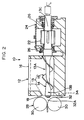
- Fig. 2 is a side sectional view illustrating the screw for a double-shaft extruding device and the double-shaft extruding device of the embodiment of the present invention.
- Fig. 3A is a side view illustrating the screw for a double-shaft extruding device of the embodiment of the present invention.
- Fig. 3B is an unfolded view illustrating the screw for a double-shaft extruding device of the embodiment of the present invention.
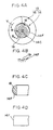
- Fig. 4A is a front view illustrating a distal end portion of the screw for a double-shaft extruding device of the embodiment of the present invention.
- Fig. 4B is a sectional view taken along line B-B of Fig. 4A.
- Figs. 4C, 4D illustrate distal end portions of the screw for a double-shaft extruding device of the embodiment of the present invention.
- Fig. 5 is a graph illustrating a relationship between an angle along a flight of the screw for a double-shaft extruding device and a cross-sectional area of extrusion.
- Fig. 6 is a plan sectional view illustrating a conventional screw for a double-shaft extruding device and a conventional double-shaft extruding device.
- Fig. 7 is a side sectional view illustrating a conventional screw for a double-shaft extruding device and a conventional double-shaft extruding device.
- two screws 13 are rotatably disposed so as to be parallel to each other within the same horizontal plane in a cylindrical casing 12 of a double-shaft extruding device 10 of the present embodiment.
- the screw 13 is provided with a shaft 14 and a spiral flight 15.
- the flight 15 is provided at the outer peripheral portion of the shaft 14 continuously from a shaft distal end 14A to a shaft proximal end 14B such that a height H of the flight 15 from an axis 14C of the shaft 14 is substantially constant.
- the respective flights 15 of the two screws 13 turn in opposite directions.
- a distal end portion 14D (over a length L1) of the shaft 14 tapers such that the axial radius D1 thereof becomes greater in the direction of the distal end.
- An axial radius D2 of a proximal end portion 14E (over a length L2) of the shaft 14 is substantially constant and only tapers in a vicinity of the proximal end so as to become greater in the direction of the proximal end.
- the angle of torsion ⁇ of the spiral of the flight 15 becomes smaller in the direction of the distal end of the shaft 14.
- the areas of the planes D1, D2,...D6, which are formed by the two opposing flights 15 and the shafts 14 and which are orthogonal to the conveying directions of the material to be extruded continuously become greater from the shaft distal end 14A to the shaft proximal end 14B.
- the cross-sectional area S of extrusion formed by the shaft 14 and the flight 15 continuously becomes greater from the shaft distal end 14A to the shaft proximal end 14B, as illustrated by graph B in Fig. 5.
- the cross-sectional area S of extrusion is the area of the planes D1, D2, D3 which are orthogonal to the conveying directions of the material to be extruded (the directions of arrows A1, A2, A3 in Fig. 3B) and which are formed by the shaft 14, the flight 15 and an imaginary flight 17 provided at the shaft distal end 14A so as to be orthogonal to the axis 14C of the shaft 14.
- a head portion 14F of the shaft 14 which projects from the shaft distal end 14A of the screw 13 is formed as a truncated cone.
- grooves 19, each having an arc-shaped sectional configuration are formed in the head portion 14F of the screw 13 for an extruding device in a swirl around the axis 14C in a direction (the direction of arrow W in Fig. 4A) opposite to the direction of turning of the flight 15 (the direction of arrow V in Fig. 4A).
- the direction of the grooves of the head portion 14F is opposite the torsional direction of the flight 15.
- the area of the head portion 14F is also large.
- a spiral groove is formed in the shaft distal end portion of the screw for an extruding device in the direction opposite to the torsional direction of the flight.
- the distal end portion may be formed as a bowl-shape, as illustrated in Fig. 4C, or may be shaped as a flat board, as illustrated in Fig. 4D.
- the spiral grooves 19 illustrated in Fig. 4A are provided on the surface of the head portion 14F of Fig. 4D.
- a hopper 16 having a top opening is provided at the side of the cylindrical casing 12 at the proximal end portion of the screw 13.
- the portion of the screw 13 which opposes the hopper 16 is a feed portion 13A.
- the feed portion 13A corresponds to the proximal end portion 14E (over the length L2) of the shaft 14 (see Fig. 3A).
- the distal end portion of the screw 13 is a compression portion 13B which corresponds to the distal end portion 14D (over the length L1) of the shaft 14 (see Fig. 3A).
- the hopper 16 is disposed so as to extend over the respective feed portions 13A of the two screws 13.
- the respective outer peripheries of the compression portions 13B are covered by the inner peripheral wall of the cylindrical casing 12.
- respective base portions 13C of the screws 13 project from the cylindrical casing 12.
- Gears 22 are provided on the portions which project.
- the gears 22 mesh with each other.
- the respective base portions 13C of the screws 13 are supported to a gear case 24 at two places via bearings 26.
- the end portion of the base portion 13C of one of the screws 13 is connected to a driving device (unillustrated).
- the directions of rotation are directions in which the material to be extruded, which is supplied from the hopper 16, is taken in between the two screws 13.
- the directions of rotation of the two screws 13 are directions which convey the taken-in material to be extruded toward the discharge opening 18 side.
- a roller die 28 is disposed ahead of the discharge opening 18 at a slight distance from the discharge opening 18.
- the roller die 28 is formed by a pair of rollers 30 which are disposed vertically such that the horizontal axes thereof are orthogonal to the axial direction of the screws 13.
- the rollers 30 are driven by a driving device (unillustrated).
- the respective axial direction lengths of the rollers 30 are slightly longer than the width of the discharge opening 18 in a direction orthogonal to the axis 14C of the shaft 14.
- Side guides 32 which prevent the material to be extruded from flowing out from the discharge opening 18 in transverse directions, are provided at both end portions of the rollers 30 in a direction orthogonal to the axis 14C of the shaft 14.
- the side guides 32 are fixed to the front surface of the cylindrical casing 12 by bolts 34 or the like.
- a front portion 32A of the side guide 32 is formed as a curved surface which runs along the peripheral surface of the roller 30.
- the material to be extruded such as rubber or the like, which is supplied to the hopper 16 is taken in by the feed portions 13A of the two screws 13 which are rotating in opposite directions and in directions of taking in the material to be extruded.
- the material to be extruded is conveyed to the compression portions 13B at the distal end side by the flights 15 of the feed portions 13A, and the pressure increases.
- the material to be extruded, which is subject to the increased pressure, is extruded into a sheet form from the discharge opening 18 via the roller die 28.
- the distal end portion 14D (over length L1) of the shaft 14 of the screw 13 tapers such that the axial radius D1 thereof becomes larger toward the distal end. Due to the optimal value of the angle of torsion ⁇ of the flight 15, the relation between the rotation angle around the shaft 14 and the cross-sectional area S of extrusion always varies smoothly as illustrated by graph B in Fig. 5. There is no region W in which the cross-sectional area S of extrusion does not vary, as there is in the conventional art. As a result, the material to be extruded can be smoothly discharged and completely extruded. Therefore, material to be extruded does not remain on the screws 13, and there is no need for an operation to remove the material to be extruded. Productivity can thereby be improved.
- the angle of torsion ⁇ of the spiral of the flight 15 becomes small toward the distal end of the shaft 14.
- the cross-sectional area S of extrusion which is formed by the shaft 14 and the flight 15 continuously increases from the shaft distal end 14A to the shaft proximal end 14B. Accordingly, the material to be extruded is easily taken in at the proximal end portions of the screws 13, i.e., at the feed portions 13A. The filling of the material to be extruded at the distal end portions of the screws 13, i.e., at the compression portions 13B, can be effected efficiently. The discharge ability greatly improves.
- the grooves 19, having arc-shaped sectional configurations and turning in a direction (the direction of arrow W in Fig. 4A) opposite to the direction of turning of the flight 15 (the direction of arrow V in Fig. 4A) are formed in a vortex shape around the axis 14C. Therefore, the material to be extruded separates easily from the head portion 14F of the shaft 14 of the screw 13, and the adhering of the material to be extruded to the head portion 14F can be prevented.
Landscapes
- Engineering & Computer Science (AREA)
- Mechanical Engineering (AREA)
- Manufacturing & Machinery (AREA)
- Extrusion Moulding Of Plastics Or The Like (AREA)
Claims (13)
- Schnecke für eine Doppelwellen-Extrudiervorrichtung (10), mit:einer Welle (14); undeinem spiralförmigen Schraubengang (15), der fortlaufend von einem distalen Wellenende (14A) zu einem proximalen Wellenende (14B) an einem Außenumfangsabschnitt der Welle (14) vorgesehen ist, und dessen Höhe (H) von einer Achse (14C) der Welle (14) im wesentlichen konstant ist, wobei sich die Gewindesteigung des spiralförmigen Schraubengangs (15) von dem distalen Wellenende (14A) zu dem proximalen Wellenende (14B) erhöht,
dadurch gekennzeichnet, daßsich eine Extrusions-Querschnittsfläche (S), die durch Ebenen (D1..D6) gebildet wird, die sich zwischen der Welle (14) und dem Schraubengang (15) erstrecken und senkrecht zu den Förderrichtungen (A1..A6) in dem Schraubengang (15) eines zu extrudierenden Materials sind, von dem distalen Wellenende (14A) zu dem proximalen Wellenende (14B) fortlaufend erhöht. - Schnecke für eine Doppelwellen-Extrudiervorrichtung gemäß Anspruch 1, wobeisich an einem Bereich des distalen Endabschnitts (14D) des Schraubengangs (15) eine Extrusions-Querschnittsfläche (S), die durch Ebenen (D1..D3) gebildet wird,die sich zwischen der Welle (14), dem Schraubengang (15) und einem gedachten Schraubengang (17) erstrecken, der an dem distalen Wellenende (14A) vorgesehen ist und sich senkrecht zu der Achse (14C) der Welle (14) erstreckt,und die senkrecht zu Förderrichtungen (A1..A3) in dem Schraubengang (15) eines zu extrudierenden Materials sind,fortlaufend von dem distalen Wellenende (14A) für einen Abstand vergrößert, der einer Drehung der Welle (14) entspricht.
- Schnecke für eine Doppelwellen-Extrudiervorrichtung gemäß Anspruch 1, wobei ein Winkel () der Drehung einer Spirale des Schraubengangs (15) in Richtung des distalen Wellenendes (14) kleiner wird.
- Schnecke für eine Doppelwellen-Extrudiervorrichtung nach einem der Ansprüche 1 bis 3, wobei sich ein distaler Endabschnitt (14D) der Welle (14) derart verjüngt, daß ein axialer Radius (d1) des distalen Endabschnitts (14D) in Richtung des distalen Wellenendes (14A) größer wird.
- Schnecke für eine Doppelwellen-Extrudiervorrichtung nach einem der Ansprüche 1 bis 4, wobei spiralförmige Nuten (19) mit einer Richtung entgegengesetzt einer Drehrichtung des Schraubengangs (15) in einem distalen Endabschnitt (14F) der Welle (14) ausgebildet sind.
- Schnecke für eine Doppelwellen-Extrudiervorrichtung nach Anspruch 5, wobei die spiralförmigen Nuten (19) konkave Abschnitte sind, die jeweils einen bogenförmigen Querschnitt aufweisen.
- Schnecke für eine Doppelwellen-Extrudiervorrichtung nach einem der Ansprüche 1 bis 6, wobei ein distaler Endabschnitt (14F) der Welle (14) als ein Kegelstumpf ausgebildet ist.
- Schnecke für eine Doppelwellen-Extrudiervorrichtung nach einem der Ansprüche 1 bis 6, wobei der distale Endabschnitt (14F) der Welle (14) schalenförmig ist.
- Schnecke für eine Doppelwellen-Extrudiervorrichtung nach einem der Ansprüche 1 bis 6, wobei der distale Endabschnitt (14F) der Welle (14) als ein flaches Brett geformt ist.
- Doppelwellen-Extrudiervorrichtung mit zwei Schrauben (13, 13) nach einem der Ansprüche 1 bis 9, wobei die Schrauben (13, 13) derart angeordnet sind, daß ihre jeweiligen Achsen parallel sind.
- Doppelwellen-Extrudiervorrichtung nach Anspruch 10, ferner mit:einem Walzenstempel (28), der an eine Auslaßöffnung (18) anliegend angeordnet ist, die in einer Umgebung eines distalen Endabschnitts (13B) der Schnecke (13) vorgesehen ist.
- Doppelwellen-Extrudiervorrichtung nach Anspruch 10 oder 11, ferner mit:Seitenführungen (32), die an Querrichtungs-Endabschnitten des Walzenstempels (28) vorgesehen sind.
- Doppelwellen-Extrudiervorrichtung nach Anspruch 12, wobei ein Abschnitt der Seitenführung (32) in einer Ausstoßrichtung als eine gekrümmte Oberfläche entlang einer Umfangsfläche des Walzenstempels (28) ausgebildet ist.
Applications Claiming Priority (4)
| Application Number | Priority Date | Filing Date | Title |
|---|---|---|---|
| JP287785/92 | 1992-10-26 | ||
| JP4287785A JPH06166086A (ja) | 1992-10-26 | 1992-10-26 | 2軸押出装置用スクリュー及び2軸押出装置 |
| JP4328995A JPH06155549A (ja) | 1992-11-16 | 1992-11-16 | 押出機用スクリュー |
| JP328995/92 | 1992-11-16 |
Publications (2)
| Publication Number | Publication Date |
|---|---|
| EP0595112A1 EP0595112A1 (de) | 1994-05-04 |
| EP0595112B1 true EP0595112B1 (de) | 1998-02-04 |
Family
ID=26556880
Family Applications (1)
| Application Number | Title | Priority Date | Filing Date |
|---|---|---|---|
| EP93116543A Expired - Lifetime EP0595112B1 (de) | 1992-10-26 | 1993-10-13 | Schnecke für Zweiwellenextruder und Zweiwellenextruder |
Country Status (3)
| Country | Link |
|---|---|
| US (2) | US5464282A (de) |
| EP (1) | EP0595112B1 (de) |
| DE (1) | DE69316824T2 (de) |
Families Citing this family (8)
| Publication number | Priority date | Publication date | Assignee | Title |
|---|---|---|---|---|
| CH690612A5 (de) * | 1995-09-21 | 2000-11-15 | Antogi Ag | Lagerung der Antriebswellen einer Schneckenpresse. |
| IT1303885B1 (it) * | 1998-11-30 | 2001-03-01 | Techint Spa | Rotore per macchine di mescolazione di elastomeri e simili con angolod'ingresso nella mescola variato lungo lo sviluppo di almeno una delle |
| JP2000246731A (ja) * | 1999-03-02 | 2000-09-12 | Kobe Steel Ltd | 混練ロータとこれを有する混練機 |
| US8668389B2 (en) | 2000-11-07 | 2014-03-11 | Davis-Standard, Llc | Combination thrust flange and thrust plate |
| US7993062B2 (en) | 2000-11-07 | 2011-08-09 | Davis-Standard, Llc | Combination thrust flange and thrust plate |
| US20030206482A1 (en) * | 2002-05-01 | 2003-11-06 | Griggs Jimmy L. | Extrusion screw tip |
| DE102006011067A1 (de) * | 2006-03-08 | 2007-09-13 | Krauss-Maffei Kunststofftechnik Gmbh | Extruder-/Spritzgießschnecke |
| CN106696225A (zh) * | 2015-07-15 | 2017-05-24 | 安徽泽加业粉体工程有限公司 | 一种新型粘性块状物料挤条机 |
Family Cites Families (10)
| Publication number | Priority date | Publication date | Assignee | Title |
|---|---|---|---|---|
| US2693617A (en) * | 1952-05-28 | 1954-11-09 | Western Electric Co | Apparatus for advancing and plasticizing plastic compounds |
| DE962745C (de) * | 1953-07-31 | 1957-04-25 | Dynamit Nobel Ag | Vorrichtung zur fortlaufenden Herstellung von Folien oder Bahnen aus thermoplastischen Kunststoffen |
| GB749919A (en) * | 1953-09-23 | 1956-06-06 | Harold Newby | Improvements in and apparatus for the production of blown foils of hard polyvinyl chloride |
| US3901486A (en) * | 1973-04-20 | 1975-08-26 | Tokyo Tobari Co Ltd | Apparatus for melting raw thermoplastic synthetic resin material |
| JPS55166234A (en) * | 1979-06-12 | 1980-12-25 | Kobe Steel Ltd | Noncontact type extruding machine with roller die |
| JPS59167240A (ja) * | 1983-03-14 | 1984-09-20 | Chisso Corp | 有機フイラ−を配合された熱可塑性樹脂組成物の成形物の製法及びそのための装置 |
| DE3600396A1 (de) * | 1985-11-09 | 1987-05-14 | Reifenhaeuser Masch | Breitschlitzduesenwerkzeug zum strangpressen von mehrschichtigen laminaten aus thermoplastischem kunststoff |
| JP2546880B2 (ja) * | 1987-08-06 | 1996-10-23 | 株式会社神戸製鋼所 | スクリュー押出機 |
| US4872761A (en) * | 1988-05-12 | 1989-10-10 | Paul Geyer | Extrusion apparatus |
| US5114658A (en) * | 1990-11-15 | 1992-05-19 | E. I. Du Pont De Nemours And Company | One step preparation and fabrication of partially grafted flexible thermoplastic compositions |
-
1993
- 1993-10-13 EP EP93116543A patent/EP0595112B1/de not_active Expired - Lifetime
- 1993-10-13 DE DE69316824T patent/DE69316824T2/de not_active Expired - Fee Related
- 1993-10-26 US US08/141,022 patent/US5464282A/en not_active Expired - Fee Related
-
1995
- 1995-05-02 US US08/433,209 patent/US5545024A/en not_active Expired - Fee Related
Also Published As
| Publication number | Publication date |
|---|---|
| US5545024A (en) | 1996-08-13 |
| EP0595112A1 (de) | 1994-05-04 |
| US5464282A (en) | 1995-11-07 |
| DE69316824T2 (de) | 1998-06-18 |
| DE69316824D1 (de) | 1998-03-12 |
Similar Documents
| Publication | Publication Date | Title |
|---|---|---|
| JP3472391B2 (ja) | 2軸押出機及びその2軸押出機を利用した押出方法 | |
| EP0595112B1 (de) | Schnecke für Zweiwellenextruder und Zweiwellenextruder | |
| US5127741A (en) | High-performance extruder | |
| US4534652A (en) | Multishafted, continuous mixing and kneading of plastifiable materials | |
| EP0292584B1 (de) | Verfahren zum Herstellen von Platten, Vorrichtung zur Ausführung des Verfahrens und erhaltene Platten | |
| DE3817941C2 (de) | ||
| US3881708A (en) | Mixing extruders | |
| JPS6155455B2 (de) | ||
| JPS60202723A (ja) | 連続式混合およびせん断ロ−ルミル | |
| JPH0571022B2 (de) | ||
| US5153009A (en) | Extrusion device | |
| EP1476290B1 (de) | Vorrichtung zum dispergieren und aufschmelzen fliessf higer stoffe | |
| EP0806280B1 (de) | Vorrichtung und Anlage zur Aufbereitung von Kunststoffgut | |
| DE3872078T2 (de) | Gasaustreibvorrichtung fuer einen kneter fuer viskoses oder fuer aehnliches material. | |
| US4058298A (en) | Screw extruder with an enlarged feed section | |
| JP3812964B2 (ja) | 2軸押出機 | |
| JP3428991B2 (ja) | 素材搬送・混合・練成装置 | |
| US5221504A (en) | Process and apparatus for optimal operation of a high-speed extruder | |
| US6550954B1 (en) | Method for producing a compound from a flowable plastic material and a solid fiber core by means of extrusion and device for carrying out said method | |
| US3184790A (en) | Screw for the cold feed extruder of the compounded rubber | |
| US4643661A (en) | Twin-screw extrusion device | |
| JPH06155549A (ja) | 押出機用スクリュー | |
| JPH06166086A (ja) | 2軸押出装置用スクリュー及び2軸押出装置 | |
| US5064364A (en) | Apparatus for the continuous coating of cylindrical workpieces with a resilient material | |
| JPH06218790A (ja) | 二軸スクリュー押出機 |
Legal Events
| Date | Code | Title | Description |
|---|---|---|---|
| PUAI | Public reference made under article 153(3) epc to a published international application that has entered the european phase |
Free format text: ORIGINAL CODE: 0009012 |
|
| AK | Designated contracting states |
Kind code of ref document: A1 Designated state(s): DE FR GB IT |
|
| 17P | Request for examination filed |
Effective date: 19940630 |
|
| 17Q | First examination report despatched |
Effective date: 19951201 |
|
| GRAG | Despatch of communication of intention to grant |
Free format text: ORIGINAL CODE: EPIDOS AGRA |
|
| GRAG | Despatch of communication of intention to grant |
Free format text: ORIGINAL CODE: EPIDOS AGRA |
|
| GRAH | Despatch of communication of intention to grant a patent |
Free format text: ORIGINAL CODE: EPIDOS IGRA |
|
| GRAH | Despatch of communication of intention to grant a patent |
Free format text: ORIGINAL CODE: EPIDOS IGRA |
|
| GRAA | (expected) grant |
Free format text: ORIGINAL CODE: 0009210 |
|
| AK | Designated contracting states |
Kind code of ref document: B1 Designated state(s): DE FR GB IT |
|
| REF | Corresponds to: |
Ref document number: 69316824 Country of ref document: DE Date of ref document: 19980312 |
|
| ITF | It: translation for a ep patent filed | ||
| ET | Fr: translation filed | ||
| PLBE | No opposition filed within time limit |
Free format text: ORIGINAL CODE: 0009261 |
|
| STAA | Information on the status of an ep patent application or granted ep patent |
Free format text: STATUS: NO OPPOSITION FILED WITHIN TIME LIMIT |
|
| 26N | No opposition filed | ||
| PGFP | Annual fee paid to national office [announced via postgrant information from national office to epo] |
Ref country code: FR Payment date: 19991011 Year of fee payment: 7 |
|
| PGFP | Annual fee paid to national office [announced via postgrant information from national office to epo] |
Ref country code: GB Payment date: 19991013 Year of fee payment: 7 |
|
| PGFP | Annual fee paid to national office [announced via postgrant information from national office to epo] |
Ref country code: DE Payment date: 19991018 Year of fee payment: 7 |
|
| PG25 | Lapsed in a contracting state [announced via postgrant information from national office to epo] |
Ref country code: GB Free format text: LAPSE BECAUSE OF NON-PAYMENT OF DUE FEES Effective date: 20001013 |
|
| GBPC | Gb: european patent ceased through non-payment of renewal fee |
Effective date: 20001013 |
|
| PG25 | Lapsed in a contracting state [announced via postgrant information from national office to epo] |
Ref country code: FR Free format text: LAPSE BECAUSE OF NON-PAYMENT OF DUE FEES Effective date: 20010629 |
|
| PG25 | Lapsed in a contracting state [announced via postgrant information from national office to epo] |
Ref country code: DE Free format text: LAPSE BECAUSE OF NON-PAYMENT OF DUE FEES Effective date: 20010703 |
|
| REG | Reference to a national code |
Ref country code: FR Ref legal event code: ST |
|
| PG25 | Lapsed in a contracting state [announced via postgrant information from national office to epo] |
Ref country code: IT Free format text: LAPSE BECAUSE OF NON-PAYMENT OF DUE FEES;WARNING: LAPSES OF ITALIAN PATENTS WITH EFFECTIVE DATE BEFORE 2007 MAY HAVE OCCURRED AT ANY TIME BEFORE 2007. THE CORRECT EFFECTIVE DATE MAY BE DIFFERENT FROM THE ONE RECORDED. Effective date: 20051013 |