EP0594544A1 - An adapter for connecting a multi-phase box-shaped switch to parallel bus-bars - Google Patents
An adapter for connecting a multi-phase box-shaped switch to parallel bus-bars Download PDFInfo
- Publication number
- EP0594544A1 EP0594544A1 EP93830231A EP93830231A EP0594544A1 EP 0594544 A1 EP0594544 A1 EP 0594544A1 EP 93830231 A EP93830231 A EP 93830231A EP 93830231 A EP93830231 A EP 93830231A EP 0594544 A1 EP0594544 A1 EP 0594544A1
- Authority
- EP
- European Patent Office
- Prior art keywords
- bars
- adapter
- bus
- switch
- rigid
- Prior art date
- Legal status (The legal status is an assumption and is not a legal conclusion. Google has not performed a legal analysis and makes no representation as to the accuracy of the status listed.)
- Granted
Links
Images
Classifications
-
- H—ELECTRICITY
- H02—GENERATION; CONVERSION OR DISTRIBUTION OF ELECTRIC POWER
- H02B—BOARDS, SUBSTATIONS OR SWITCHING ARRANGEMENTS FOR THE SUPPLY OR DISTRIBUTION OF ELECTRIC POWER
- H02B1/00—Frameworks, boards, panels, desks, casings; Details of substations or switching arrangements
- H02B1/015—Boards, panels, desks; Parts thereof or accessories therefor
- H02B1/04—Mounting thereon of switches or of other devices in general, the switch or device having, or being without, casing
- H02B1/056—Mounting on plugboards
- H02B1/0565—Mounting on plugboards by means of an adapter carrying one or more apparatuses
-
- H—ELECTRICITY
- H02—GENERATION; CONVERSION OR DISTRIBUTION OF ELECTRIC POWER
- H02B—BOARDS, SUBSTATIONS OR SWITCHING ARRANGEMENTS FOR THE SUPPLY OR DISTRIBUTION OF ELECTRIC POWER
- H02B1/00—Frameworks, boards, panels, desks, casings; Details of substations or switching arrangements
- H02B1/20—Bus-bar or other wiring layouts, e.g. in cubicles, in switchyards
- H02B1/21—Bus-bar arrangements for rack-mounted devices with withdrawable units
Definitions
- This invention relates to structures for mounting apparatus to electrical panelboards, and in particular, to an adapter for connecting a multi-phase box-shaped switch to parallel bus-bars.
- bus-bars In electrical panelboards for civil and industrial systems, ample use is made of distribution conductors in the form of metal bus-bars arranged parallel to one another in sets of three orfour, and frequently laid horizontally.
- the bus-bars are connected directly to the mains by specially provided terminals, and from them the various apparatus in the system are supplied through suitable switches mounted close to respective sets of bus-bars.
- the switches may be connected electrically, and often mechanically as well, to a set of bus-bars in a variety of ways.
- connection structures consisting of metal conductors held together by insulating crosspieces and arranged for connection -- using bolts, clamps, or otherfasteners located within easy reach from the panelboard front -- with one end to the bus-bars, and with anotherend to the input connections of the switches.
- a known adapter comprises a body made of an insulating material and having a forward surface acting as a bearing surface for the base of a switch to be mounted, and a rearward surface having means of attachment to the bus-bars. Led out from the body are as many electric conductors, e.g.
- Each conductor is joined, with one end, to an attachment member, located within reach from the front, for attachment to a respective bus-bar.
- the opposite end of each conductor is adapted for attachment to an input connection of the switch.
- bus-bars are connected to the mains with the intermediary of a master switch, rather than directly thereto.
- the master switch can be connected, through its output connections, to the bus-bars using either a rigid mount or an adapter, as outlined above.
- the former method has the aforementioned disadvantage of taking up space, while the latter involves the use of an adapter having its electric connection conductors led out of the opposite side with respect to the adapter previously described. It matters to observe that it is impossible to use one adapter in either cases by merely turning it 180° around because the attachment means would then be overturned, thereby making the adapter awkward to mount to a vertical panelboard, and the connection order of the phases would be reversed, which may not infrequently result in the connections getting mixed up. It should also be noted that standard multi-phase, box-shaped toggle switches should be mounted to a vertical panelboard such that theirtoggles are moved down from above in order to set the switch to its break position from the make position. Thus, the switch cannot be turned around to utilize the same adapter for connecting the bus-bars either to the input or the output connections.
- a multi-phase box-shaped switch is to be connected, both mechanically and electrically through its output connections, to four bus-bars, indicated at 11, of a vertical panelboard, no further shown.
- This connection is made possible by an adapter, generally shown at 12, according to the invention.
- the switch 10 has an operation toggle 14, shown pushed upwards, i.e. into the switch make setting, four connections 15 with respective screw fasteners 16 on the bottom side, and four connections 17 with respective screw fasteners 18 on the top side.
- the upper four connections 17 are assumed to be the input connections, the lower four connections 15 being the output connections.
- the adapter 12 is basically comprised of a body 20 formed from an insulating material as two shaped elements 20a and 20b being expendiently plastics moldings held together by some suitable means, such as reversible interlock means, and four rigid electric conductors 21, expediently in the form of copper strips.
- the element 20a of the body 20 has, on its outward face 22, a rib 23 which defines a bearing area for the switch 10 base edge.
- the two shaped elements 20a and 20b are formed internally, as shown best in Figure 2, with four parallel longitudinal channels 26 constituting receiving seats designed to hold the rigid conductors 21 slidably therein.
- the conductors are shaped with one end portion bent to a U-like pattern and the other end portion straight for insertion into the adapter seats. This can be done from either side of the adapter. As can be seen, the straight portions have progressively longer lengths so that, once fitted into the seats 26, each straight portion will locate with its end portion overlying one of the bus-bars 11.
- each connector 25 comprises a piece of metal, preferably copper, having a base 25a through-penetrated by a threaded hole 25b, and two substantially C-shaped elements 25c which extend at right angles from the base 25a, a small plate 25d of the same material, and a screw 29 adapted for engagement in the threaded hole 25b.
- the free ends of the elements 25c jointly provide a sort of hook for mounting the adapter 12 to the bus-bars 11.
- the adapter further includes four pairs of elastic elements 27, expediently integral with the shaped element 20a of the body 20, located on either opposite sides thereof crosswise to the seats 26.
- Each of said element pairs locate close to the end of one seat 26 and have two oppositely located dogs 28 forming a reversible detent arrangement for a rigid conductor 21 fitted inside the seat.
- the procedure for mounting the switch 10 to the bus-bars 11 using the adapter 12 comprises the following sequential steps:
- the switch 10 must be connected to the bus-bars 11 by its upper connections, i.e. the input ones, rather than its lower or output connections, the rigid conductors 21 are simply inserted into the seats 26 of the adapter 12 top side in the reverse order, that is with the shortest on the right, ratherthan on the left as in the previous example, and the longest on the left, rather than on the right.
- the adapter of this invention additionally to being simple in construction and, hence, economical to manufacture, can be used for mounting switches to bus-bars indifferently by the input or the output connections.
- the rigid conductors could have their ends inside the body, rather than perfectly straight, made with one or more steps, or elevations, or recesses, for a more precise and stable fit of same in their seats; furthermore, they may have a round, instead of square, cross-sectional shape, for use with switches having round cross-section connections for the conductors, and accordingly, the seats, connectors, and detent means provided on the adapter body would be altered to suit the different shapes of the conductors; or the rigid conductors, once fitted in their seats, could have the crosspieces of their U-shaped parts in different planes and have the free legs of the "U" with different lengths, that is they could project unevenly from the adapter where needed to fill special mounting demands; obviously, the adapter of this invention may also be provided for switches having a number of poles other than four.
Abstract
Description
- This invention relates to structures for mounting apparatus to electrical panelboards, and in particular, to an adapter for connecting a multi-phase box-shaped switch to parallel bus-bars.
- In electrical panelboards for civil and industrial systems, ample use is made of distribution conductors in the form of metal bus-bars arranged parallel to one another in sets of three orfour, and frequently laid horizontally. In many cases, the bus-bars are connected directly to the mains by specially provided terminals, and from them the various apparatus in the system are supplied through suitable switches mounted close to respective sets of bus-bars. The switches may be connected electrically, and often mechanically as well, to a set of bus-bars in a variety of ways. One of these uses rigid connection structures consisting of metal conductors held together by insulating crosspieces and arranged for connection -- using bolts, clamps, or otherfasteners located within easy reach from the panelboard front -- with one end to the bus-bars, and with anotherend to the input connections of the switches. Another, more advantageous, because less bulky, connection arrangement provides for the use of adapters which allow the switches to be mounted directly on the bus-bars. A known adapter comprises a body made of an insulating material and having a forward surface acting as a bearing surface for the base of a switch to be mounted, and a rearward surface having means of attachment to the bus-bars. Led out from the body are as many electric conductors, e.g. cables, as are the phases of the switch to be mounted on the adapter. Each conductor is joined, with one end, to an attachment member, located within reach from the front, for attachment to a respective bus-bar. The opposite end of each conductor is adapted for attachment to an input connection of the switch.
- In some cases, the bus-bars are connected to the mains with the intermediary of a master switch, rather than directly thereto. The master switch can be connected, through its output connections, to the bus-bars using either a rigid mount or an adapter, as outlined above.
- However, the former method has the aforementioned disadvantage of taking up space, while the latter involves the use of an adapter having its electric connection conductors led out of the opposite side with respect to the adapter previously described. It matters to observe that it is impossible to use one adapter in either cases by merely turning it 180° around because the attachment means would then be overturned, thereby making the adapter awkward to mount to a vertical panelboard, and the connection order of the phases would be reversed, which may not infrequently result in the connections getting mixed up. It should also be noted that standard multi-phase, box-shaped toggle switches should be mounted to a vertical panelboard such that theirtoggles are moved down from above in order to set the switch to its break position from the make position. Thus, the switch cannot be turned around to utilize the same adapter for connecting the bus-bars either to the input or the output connections.
- It is the object of this invention to provide an adapter for a multi-phase box-shaped switch of simple construction, which can be used equally well in either of the above mounting schemes.
- This object is achieved by an adapter as generally defined and characterized in the first of the appended claims to this specification.
- The invention can be better understood by making reference to the following detailed description of an embodiment thereof, to be taken by way of example and not of limitation in conjunction with the accompanying drawing, in which:
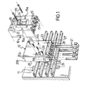
- Figure 1 is an exploded perspective view showing an adapter according to the invention, a set of bus-bars on which the adapter can be mounted, and a multi-phase box-shaped switch for attachment to the adapter;
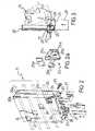
- Figure 2 is a perspective view of the adapter taken from its side next to the bus-bars;
- Figure 2a is an enlarged detail view of the adapter; and
- Figure 3 is a side view illustrating a step of the procedure for mounting a switch on the adapter.
- With reference to Figure 1, a multi-phase box-shaped switch, generally shown at 10, is to be connected, both mechanically and electrically through its output connections, to four bus-bars, indicated at 11, of a vertical panelboard, no further shown. This connection is made possible by an adapter, generally shown at 12, according to the invention.
- The
switch 10 has an operation toggle 14, shown pushed upwards, i.e. into the switch make setting, fourconnections 15 withrespective screw fasteners 16 on the bottom side, and fourconnections 17 with respective screw fasteners 18 on the top side. In a conventional way, the upper fourconnections 17 are assumed to be the input connections, the lower fourconnections 15 being the output connections. - The
adapter 12 is basically comprised of abody 20 formed from an insulating material as twoshaped elements electric conductors 21, expediently in the form of copper strips. Theelement 20a of thebody 20 has, on itsoutward face 22, arib 23 which defines a bearing area for theswitch 10 base edge. The twoshaped elements longitudinal channels 26 constituting receiving seats designed to hold therigid conductors 21 slidably therein. The conductors are shaped with one end portion bent to a U-like pattern and the other end portion straight for insertion into the adapter seats. This can be done from either side of the adapter. As can be seen, the straight portions have progressively longer lengths so that, once fitted into theseats 26, each straight portion will locate with its end portion overlying one of the bus-bars 11. - The
shaped element 20b of thebody 20 has four diagonally arranged windows, shown at 24, whence there protrude the ends of asmany connectors 25 used for securing and connecting electrically therigid conductors 21 to their respective bus-bars 11. As shown in Figure 2a, eachconnector 25 comprises a piece of metal, preferably copper, having abase 25a through-penetrated by a threadedhole 25b, and two substantially C-shaped elements 25c which extend at right angles from thebase 25a, a small plate 25d of the same material, and ascrew 29 adapted for engagement in the threadedhole 25b. The free ends of theelements 25c jointly provide a sort of hook for mounting theadapter 12 to the bus-bars 11. - The adapter further includes four pairs of
elastic elements 27, expediently integral with theshaped element 20a of thebody 20, located on either opposite sides thereof crosswise to theseats 26. Each of said element pairs locate close to the end of oneseat 26 and have two oppositely locateddogs 28 forming a reversible detent arrangement for arigid conductor 21 fitted inside the seat. - The procedure for mounting the
switch 10 to the bus-bars 11 using theadapter 12 comprises the following sequential steps: - mounting the
connectors 25 inside theshaped element 20b (the plates 25d being fitted and held in place on thewindows 24 by suitable retaining means, not shown); - inserting the
conductors 21 into theseats 26 of the adapter from either side thereof, according to whether theswitch 10 is to be connected to the bus-bars by its input or output connections, until thedetent dogs 28 snap over the outward side of the crosspieces of the respective U-shaped parts; - hooking the
adapter 12 with theends 25c of theconnectors 25 onto the bus-bars 11; - fastening the
rigid conductors 21 to the bus-bars 11 by tightening down thescrews 29 of theconnectors 25; - applying the
switch 10 to theadapter 12 by placing theconnections 15 on the free legs of the U-shaped parts of therigid conductors 21 and moving the switch until the switch base reaches its seat; the switch will be held in place by the combined action of therib 23 and the mutual engagement of theconnections 15 with therigid conductors 21; - fastening the
switch using screws 19, through-holes 19a in the switch body, ad threadedholes 19b in the adapter body; - tightening the
screws 16 to hold therigid conductors 21 securely on theconnections 15. - Where the
switch 10 must be connected to the bus-bars 11 by its upper connections, i.e. the input ones, rather than its lower or output connections, therigid conductors 21 are simply inserted into theseats 26 of theadapter 12 top side in the reverse order, that is with the shortest on the right, ratherthan on the left as in the previous example, and the longest on the left, rather than on the right. - It will be appreciated from the foregoing that the adapter of this invention, additionally to being simple in construction and, hence, economical to manufacture, can be used for mounting switches to bus-bars indifferently by the input or the output connections.
- This represents a major advantage from the standpoint of optimizing production, because it enables the number of the products to be stored and delivered to be reduced by virtue of one and the same adapter being usable for two different applications.
- While one embodiment of the invention only has been described and illustrated, it is understood that many changes and modifications may be made thereunto without departing from the general principle of the invention. For example, the rigid conductors could have their ends inside the body, rather than perfectly straight, made with one or more steps, or elevations, or recesses, for a more precise and stable fit of same in their seats; furthermore, they may have a round, instead of square, cross-sectional shape, for use with switches having round cross-section connections for the conductors, and accordingly, the seats, connectors, and detent means provided on the adapter body would be altered to suit the different shapes of the conductors; or the rigid conductors, once fitted in their seats, could have the crosspieces of their U-shaped parts in different planes and have the free legs of the "U" with different lengths, that is they could project unevenly from the adapter where needed to fill special mounting demands; obviously, the adapter of this invention may also be provided for switches having a number of poles other than four.
Claims (6)
Applications Claiming Priority (2)
| Application Number | Priority Date | Filing Date | Title |
|---|---|---|---|
| ITMI922393A IT1255889B (en) | 1992-10-19 | 1992-10-19 | ADAPTER FOR THE CONNECTION OF A MULTI-PHASE BOX SWITCH TO PARALLEL DISTRIBUTION BARS |
| ITMI922393 | 1992-10-19 |
Publications (2)
| Publication Number | Publication Date |
|---|---|
| EP0594544A1 true EP0594544A1 (en) | 1994-04-27 |
| EP0594544B1 EP0594544B1 (en) | 1996-11-27 |
Family
ID=11364135
Family Applications (1)
| Application Number | Title | Priority Date | Filing Date |
|---|---|---|---|
| EP93830231A Expired - Lifetime EP0594544B1 (en) | 1992-10-19 | 1993-05-27 | An adapter for connecting a multi-phase box-shaped switch to parallel bus-bars |
Country Status (4)
| Country | Link |
|---|---|
| EP (1) | EP0594544B1 (en) |
| DE (1) | DE69306223T2 (en) |
| ES (1) | ES2095029T3 (en) |
| IT (1) | IT1255889B (en) |
Cited By (7)
| Publication number | Priority date | Publication date | Assignee | Title |
|---|---|---|---|---|
| EP0788205A2 (en) * | 1996-01-31 | 1997-08-06 | Schneider Electric Sa | Improvements in and relating to electrical distribution equipment |
| EP0808006A2 (en) * | 1996-04-18 | 1997-11-19 | Bticino S.P.A. | An electrical distribution board for medium-power switches |
| DE29716201U1 (en) * | 1997-09-10 | 1999-01-14 | Elek Gmbh | Connection device |
| EP1189321A1 (en) * | 2000-04-03 | 2002-03-20 | Terasaki Denki Sangyo Kabushiki Kaisha | Wiring circuit breaker and switchboard |
| FR2830677A1 (en) * | 2001-10-09 | 2003-04-11 | Schneider Electric Ind Sa | Motor load controlling electrical module having electrical connector bundles electrical control apparatus with rear section connection connecting fixing support power and base. |
| EP1544971A1 (en) * | 2003-12-17 | 2005-06-22 | ABB Service S.r.l | Busbar adapter |
| EP3399608A1 (en) | 2017-05-05 | 2018-11-07 | Zenex Sp. z o.o. | System for attaching a fuse-disconnector to a busbar |
Families Citing this family (1)
| Publication number | Priority date | Publication date | Assignee | Title |
|---|---|---|---|---|
| DE102005042746B4 (en) * | 2005-09-05 | 2015-09-24 | Siemens Aktiengesellschaft | Fuse switch |
Citations (3)
| Publication number | Priority date | Publication date | Assignee | Title |
|---|---|---|---|---|
| DE3413358A1 (en) * | 1984-04-09 | 1985-10-17 | Efen Elektrotechnische Fabrik Gmbh, 6228 Eltville | Contacting device for holding switching apparatuses |
| DE9004139U1 (en) * | 1990-04-10 | 1990-07-26 | Albrecht Jung Gmbh & Co Kg, 7965 Ostrach, De | |
| DE4124487A1 (en) * | 1990-12-22 | 1992-07-02 | Geyer Gmbh & Co Christian | Adaptor plate for bus=bar - holds several flush-mounted electrical units in clips which are adjustable to suit width of unit |
-
1992
- 1992-10-19 IT ITMI922393A patent/IT1255889B/en active IP Right Grant
-
1993
- 1993-05-27 ES ES93830231T patent/ES2095029T3/en not_active Expired - Lifetime
- 1993-05-27 EP EP93830231A patent/EP0594544B1/en not_active Expired - Lifetime
- 1993-05-27 DE DE69306223T patent/DE69306223T2/en not_active Expired - Fee Related
Patent Citations (3)
| Publication number | Priority date | Publication date | Assignee | Title |
|---|---|---|---|---|
| DE3413358A1 (en) * | 1984-04-09 | 1985-10-17 | Efen Elektrotechnische Fabrik Gmbh, 6228 Eltville | Contacting device for holding switching apparatuses |
| DE9004139U1 (en) * | 1990-04-10 | 1990-07-26 | Albrecht Jung Gmbh & Co Kg, 7965 Ostrach, De | |
| DE4124487A1 (en) * | 1990-12-22 | 1992-07-02 | Geyer Gmbh & Co Christian | Adaptor plate for bus=bar - holds several flush-mounted electrical units in clips which are adjustable to suit width of unit |
Cited By (11)
| Publication number | Priority date | Publication date | Assignee | Title |
|---|---|---|---|---|
| EP0788205A2 (en) * | 1996-01-31 | 1997-08-06 | Schneider Electric Sa | Improvements in and relating to electrical distribution equipment |
| EP0788205A3 (en) * | 1996-01-31 | 1997-12-17 | Schneider Electric Sa | Improvements in and relating to electrical distribution equipment |
| EP0808006A2 (en) * | 1996-04-18 | 1997-11-19 | Bticino S.P.A. | An electrical distribution board for medium-power switches |
| EP0808006A3 (en) * | 1996-04-18 | 1998-10-14 | Bticino S.P.A. | An electrical distribution board for medium-power switches |
| DE29716201U1 (en) * | 1997-09-10 | 1999-01-14 | Elek Gmbh | Connection device |
| EP1189321A1 (en) * | 2000-04-03 | 2002-03-20 | Terasaki Denki Sangyo Kabushiki Kaisha | Wiring circuit breaker and switchboard |
| EP1189321A4 (en) * | 2000-04-03 | 2002-11-06 | Terasaki Denki Sangyo Kk | Wiring circuit breaker and switchboard |
| FR2830677A1 (en) * | 2001-10-09 | 2003-04-11 | Schneider Electric Ind Sa | Motor load controlling electrical module having electrical connector bundles electrical control apparatus with rear section connection connecting fixing support power and base. |
| EP1544971A1 (en) * | 2003-12-17 | 2005-06-22 | ABB Service S.r.l | Busbar adapter |
| CN1638222B (en) * | 2003-12-17 | 2012-05-02 | Abb股份公司 | Device for connection of busbars to equipment of an electrical switchboard |
| EP3399608A1 (en) | 2017-05-05 | 2018-11-07 | Zenex Sp. z o.o. | System for attaching a fuse-disconnector to a busbar |
Also Published As
| Publication number | Publication date |
|---|---|
| ES2095029T3 (en) | 1997-02-01 |
| IT1255889B (en) | 1995-11-17 |
| ITMI922393A0 (en) | 1992-10-19 |
| EP0594544B1 (en) | 1996-11-27 |
| DE69306223T2 (en) | 1997-04-24 |
| DE69306223D1 (en) | 1997-01-09 |
| ITMI922393A1 (en) | 1994-04-19 |
Similar Documents
| Publication | Publication Date | Title |
|---|---|---|
| US6381122B2 (en) | Bus bar system with several bus bars and an installation device with flat connectors | |
| US3245024A (en) | Separable electrical connector for plural conductors | |
| EP0106535B1 (en) | Electrical track | |
| US7850483B2 (en) | Power meter socket to circuit breaker connection | |
| GB2024520A (en) | Electrical power distribution boards | |
| US7408766B2 (en) | Mounting and connecting means for electrical components | |
| EP0594544B1 (en) | An adapter for connecting a multi-phase box-shaped switch to parallel bus-bars | |
| US3335330A (en) | Mounting pan assembly for electrical panelboard | |
| US6459570B1 (en) | Load center interior panel with snap-in neutral | |
| GB2166914A (en) | Electrical conductor system | |
| WO1992007396A1 (en) | A modular wiring system | |
| US3769553A (en) | Panelboard with insulative snap-in support means | |
| US5064380A (en) | Electrical tap and splice connector | |
| EP0434349A1 (en) | Electrical apparatus | |
| EP2678903B1 (en) | A modular electrical connection unit | |
| US3818282A (en) | Electrical panel board with ground and neutral plug-in buses | |
| US6045379A (en) | Device connecting conductors or devices to a bus bar in a bus bar system | |
| EP0673081A2 (en) | Terminal box | |
| US2897410A (en) | Plug-in type circuit breaker panelboard | |
| CA1113164A (en) | Terminal apparatus for interconnecting two or more insulated electrical conductors | |
| US4533195A (en) | Pre-wired modular connecting blocks | |
| US2980824A (en) | Load distributing arrangement | |
| EP0808006B1 (en) | An electrical distribution board for medium-power switches | |
| JPS5951488A (en) | Interconductor repeating device of module structure | |
| JP2002135912A (en) | Voltage switching unit of single phase three-wire distribution board |
Legal Events
| Date | Code | Title | Description |
|---|---|---|---|
| PUAI | Public reference made under article 153(3) epc to a published international application that has entered the european phase |
Free format text: ORIGINAL CODE: 0009012 |
|
| AK | Designated contracting states |
Kind code of ref document: A1 Designated state(s): BE DE ES FR GB NL PT |
|
| 17P | Request for examination filed |
Effective date: 19940221 |
|
| 17Q | First examination report despatched |
Effective date: 19950807 |
|
| GRAG | Despatch of communication of intention to grant |
Free format text: ORIGINAL CODE: EPIDOS AGRA |
|
| GRAH | Despatch of communication of intention to grant a patent |
Free format text: ORIGINAL CODE: EPIDOS IGRA |
|
| RAP1 | Party data changed (applicant data changed or rights of an application transferred) |
Owner name: BTICINO S.P.A. |
|
| GRAH | Despatch of communication of intention to grant a patent |
Free format text: ORIGINAL CODE: EPIDOS IGRA |
|
| GRAA | (expected) grant |
Free format text: ORIGINAL CODE: 0009210 |
|
| AK | Designated contracting states |
Kind code of ref document: B1 Designated state(s): BE DE ES FR GB NL PT |
|
| REF | Corresponds to: |
Ref document number: 69306223 Country of ref document: DE Date of ref document: 19970109 |
|
| ET | Fr: translation filed | ||
| REG | Reference to a national code |
Ref country code: ES Ref legal event code: FG2A Ref document number: 2095029 Country of ref document: ES Kind code of ref document: T3 |
|
| REG | Reference to a national code |
Ref country code: PT Ref legal event code: SC4A Free format text: AVAILABILITY OF NATIONAL TRANSLATION Effective date: 19961128 |
|
| PLBE | No opposition filed within time limit |
Free format text: ORIGINAL CODE: 0009261 |
|
| STAA | Information on the status of an ep patent application or granted ep patent |
Free format text: STATUS: NO OPPOSITION FILED WITHIN TIME LIMIT |
|
| 26N | No opposition filed | ||
| REG | Reference to a national code |
Ref country code: GB Ref legal event code: IF02 |
|
| PGFP | Annual fee paid to national office [announced via postgrant information from national office to epo] |
Ref country code: DE Payment date: 20080514 Year of fee payment: 16 |
|
| PGFP | Annual fee paid to national office [announced via postgrant information from national office to epo] |
Ref country code: NL Payment date: 20080425 Year of fee payment: 16 |
|
| PGFP | Annual fee paid to national office [announced via postgrant information from national office to epo] |
Ref country code: ES Payment date: 20090506 Year of fee payment: 17 |
|
| PGFP | Annual fee paid to national office [announced via postgrant information from national office to epo] |
Ref country code: PT Payment date: 20090513 Year of fee payment: 17 |
|
| PGFP | Annual fee paid to national office [announced via postgrant information from national office to epo] |
Ref country code: BE Payment date: 20090429 Year of fee payment: 17 |
|
| PGFP | Annual fee paid to national office [announced via postgrant information from national office to epo] |
Ref country code: GB Payment date: 20090427 Year of fee payment: 17 |
|
| NLV4 | Nl: lapsed or anulled due to non-payment of the annual fee |
Effective date: 20091201 |
|
| PG25 | Lapsed in a contracting state [announced via postgrant information from national office to epo] |
Ref country code: NL Free format text: LAPSE BECAUSE OF NON-PAYMENT OF DUE FEES Effective date: 20091201 |
|
| PG25 | Lapsed in a contracting state [announced via postgrant information from national office to epo] |
Ref country code: DE Free format text: LAPSE BECAUSE OF NON-PAYMENT OF DUE FEES Effective date: 20091201 |
|
| BERE | Be: lapsed |
Owner name: *BTICINO S.P.A. Effective date: 20100531 |
|
| REG | Reference to a national code |
Ref country code: PT Ref legal event code: MM4A Free format text: LAPSE DUE TO NON-PAYMENT OF FEES Effective date: 20101129 |
|
| GBPC | Gb: european patent ceased through non-payment of renewal fee |
Effective date: 20100527 |
|
| PG25 | Lapsed in a contracting state [announced via postgrant information from national office to epo] |
Ref country code: PT Free format text: LAPSE BECAUSE OF NON-PAYMENT OF DUE FEES Effective date: 20101129 |
|
| PG25 | Lapsed in a contracting state [announced via postgrant information from national office to epo] |
Ref country code: BE Free format text: LAPSE BECAUSE OF NON-PAYMENT OF DUE FEES Effective date: 20100531 |
|
| REG | Reference to a national code |
Ref country code: ES Ref legal event code: FD2A Effective date: 20110715 |
|
| PG25 | Lapsed in a contracting state [announced via postgrant information from national office to epo] |
Ref country code: GB Free format text: LAPSE BECAUSE OF NON-PAYMENT OF DUE FEES Effective date: 20100527 Ref country code: ES Free format text: LAPSE BECAUSE OF NON-PAYMENT OF DUE FEES Effective date: 20110705 |
|
| PGFP | Annual fee paid to national office [announced via postgrant information from national office to epo] |
Ref country code: FR Payment date: 20110621 Year of fee payment: 19 |
|
| PG25 | Lapsed in a contracting state [announced via postgrant information from national office to epo] |
Ref country code: ES Free format text: LAPSE BECAUSE OF NON-PAYMENT OF DUE FEES Effective date: 20100528 |
|
| REG | Reference to a national code |
Ref country code: FR Ref legal event code: ST Effective date: 20130131 |
|
| PG25 | Lapsed in a contracting state [announced via postgrant information from national office to epo] |
Ref country code: FR Free format text: LAPSE BECAUSE OF NON-PAYMENT OF DUE FEES Effective date: 20120531 |