EP0808006A2 - An electrical distribution board for medium-power switches - Google Patents
An electrical distribution board for medium-power switches Download PDFInfo
- Publication number
- EP0808006A2 EP0808006A2 EP97201026A EP97201026A EP0808006A2 EP 0808006 A2 EP0808006 A2 EP 0808006A2 EP 97201026 A EP97201026 A EP 97201026A EP 97201026 A EP97201026 A EP 97201026A EP 0808006 A2 EP0808006 A2 EP 0808006A2
- Authority
- EP
- European Patent Office
- Prior art keywords
- electrical
- bars
- switch
- base
- distribution board
- Prior art date
- Legal status (The legal status is an assumption and is not a legal conclusion. Google has not performed a legal analysis and makes no representation as to the accuracy of the status listed.)
- Granted
Links
Images

Classifications
-
- H—ELECTRICITY
- H02—GENERATION; CONVERSION OR DISTRIBUTION OF ELECTRIC POWER
- H02B—BOARDS, SUBSTATIONS OR SWITCHING ARRANGEMENTS FOR THE SUPPLY OR DISTRIBUTION OF ELECTRIC POWER
- H02B1/00—Frameworks, boards, panels, desks, casings; Details of substations or switching arrangements
- H02B1/20—Bus-bar or other wiring layouts, e.g. in cubicles, in switchyards
- H02B1/21—Bus-bar arrangements for rack-mounted devices with withdrawable units
Definitions
- the present invention relates to electrical-energy distribution boards and, more particularly, to an electrical distribution board comprising one or more medium-power switches, bus bars for distributing electrical energy, and means for connecting the switch or switches to the bars.
- both domestic and industrial, small electrical distribution boards containing a few medium- power switches that is, switches which can control currents of between 60 and 160 A
- switches which can control currents of between 60 and 160 A
- it is necessary to provide suitable support and fixing means, to make the necessary electrical connections (with wires or copper strips) between the input connectors of the switches and the bus bars, which are normally arranged along a vertical side of the board, and to fit a panel for isolating the internal portion of the board containing the bars and the connecting wires from its front portion.
- the object of the present invention is to propose an electrical distribution board for which the mounting operations, both with regard to the fixing of the switches and with regard to their electrical connections to the bars, are quicker and easier than those required with known electrical distribution boards.
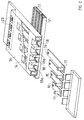
- an electrical distribution board 10 with a box-like structure to be mounted on, or flush-mounted in, a wall has, as can best be seen in Figure 4, channel-sectioned bus bars 11, arranged parallel to one another and to the back wall of the board.
- the board 10 comprises three power switches 12 of which one is shown mounted and one during the mounting stage. Each switch 12 is connected to the bars 11 through a base plate 13 of insulating, for example, plastics material which extends across the entire width of the board.
- the plate 13 since the plate 13 extends across the entire width of the board, it enables the internal portion of the board which contains uncovered, normally live, electrical conductors to be separated completely from its front portion which is accessible for the mounting of the switches and for normal maintenance operations.
- Each base plate 13 has four through-holes 14 which are square in this embodiment and which, when the plate is mounted, are disposed in the regions of respective bars 11.
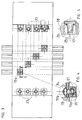
- the connecting means between the switches and the bars also comprise four rigid electrical conductors, in this embodiment, copper strips 15 which are fixed to the base plate 13 since they are inserted in suitable seats 13a provided inside the plate, as shown in Figure 2.
- the strips 15 are of different lengths and, once mounted in the plate 13, each is disposed with a first end in the region of a hole 14 and with its second end aligned with the second ends of the others.
- the first end has a through-hole 16 and the second end has an electrical connection member, in this embodiment, a frusto-conical copper appendage 17 welded to the strip 15. This appendage 17 projects from the base plate 13 through a hole 18 in the wall opposite that which bears on the bars 11.
- each of the bolts 19 releasably join the base plates 13, with the incorporated strips 15, to the bars 11.
- each of the bolts 19 extends through a hole 16 in a strip 15 and has a head 19a which engages the inner walls of the channel-sectioned bar, as well as a nut 19b which is accessible through the holes 14 in the plate 13 in order to be screwed up and tightened.
- the strips 15, and hence also the plate 13, are thus fixed to the bars 11.
- the head of the bolt 19 is rectangular with one side narrower and one side wider than the slots in the channel-sectioned bars 11, so that it can be inserted in the bar and then brought to a position of anchorage to the bar by rotation through 90°.
- a resilient element in this case, a plate spring 20 fixed in the respective bar 11, is associated with each bolt. This measure enables the bolt to be placed and held in position before and during the fitting of the plate 13, facilitating assembly and, at the same time, allowing the bolts to move along the bars so that the plate can be positioned at the desired height.
- the copper appendages 17 have plates 25 of insulating, for example, plastics material fixed to their ends, for example, by a suitable fixing and the plates 13 are shaped in a manner such that each of the appendages 17 is disposed inside a cavity 26 of dimensions such that only a narrow space remains between the conductive surface of the appendage 17 and the insulating surfaces of the plate 13.
- This space is wide enough to house the connectors 21 of the switches but is narrow enough to make it impossible for people employed to mount the switches or carry out maintenance of the electrical distribution board to contact the live electrical conductors accidentally.
Landscapes
- Engineering & Computer Science (AREA)
- Power Engineering (AREA)
- Distribution Board (AREA)
- Push-Button Switches (AREA)
- Switch Cases, Indication, And Locking (AREA)
- Coupling Device And Connection With Printed Circuit (AREA)
- Multi-Conductor Connections (AREA)
- Patch Boards (AREA)
- Refuge Islands, Traffic Blockers, Or Guard Fence (AREA)
Abstract
Description
- The present invention relates to electrical-energy distribution boards and, more particularly, to an electrical distribution board comprising one or more medium-power switches, bus bars for distributing electrical energy, and means for connecting the switch or switches to the bars.
- In some applications, both domestic and industrial, small electrical distribution boards containing a few medium- power switches, that is, switches which can control currents of between 60 and 160 A, are used. In order to mount these switches, it is necessary to provide suitable support and fixing means, to make the necessary electrical connections (with wires or copper strips) between the input connectors of the switches and the bus bars, which are normally arranged along a vertical side of the board, and to fit a panel for isolating the internal portion of the board containing the bars and the connecting wires from its front portion.
- The object of the present invention is to propose an electrical distribution board for which the mounting operations, both with regard to the fixing of the switches and with regard to their electrical connections to the bars, are quicker and easier than those required with known electrical distribution boards.
- This object is achieved, according to the invention, owing to the fact that the bars are arranged, substantially parallel to one another, in a plane substantially parallel to the back wall of the board, and that the connecting means comprise:
- a base of insulating material disposed between the switch and the bars and having a hole in the region of each bar,
- substantially rigid electrical conductors fixed to the base, insulated from one another, and each having a first end in the region of one of the holes in the base and a second end having means for connection to an electrical connector of the switch, and
- electrical and mechanical connection members which releasably join the first end of each electrical conductor to a respective bar.
- The invention will be understood better from the following detailed description of an embodiment thereof, given by way of non-limiting example with reference to the appended drawings, in which:
- Figure 1 is a front view of a board according to the invention with three switches, of which some are in the mounting stage,
- Figure 2 is a perspective view of a structure for connection between a switch and the bars of a board according to the invention, with parts separated and not to scale with Figure 1,
- Figure 3 is a plan view of the structure of Figure 2, and
- Figures 4 and 5 show two details of the structure of Figure 3, on an enlarged scale and in section.
- As can be seen in Figure 1, an
electrical distribution board 10 with a box-like structure to be mounted on, or flush-mounted in, a wall has, as can best be seen in Figure 4, channel-sectionedbus bars 11, arranged parallel to one another and to the back wall of the board. - The
board 10 comprises threepower switches 12 of which one is shown mounted and one during the mounting stage. Eachswitch 12 is connected to thebars 11 through abase plate 13 of insulating, for example, plastics material which extends across the entire width of the board. - In this embodiment, since the
plate 13 extends across the entire width of the board, it enables the internal portion of the board which contains uncovered, normally live, electrical conductors to be separated completely from its front portion which is accessible for the mounting of the switches and for normal maintenance operations. - Each
base plate 13 has four through-holes 14 which are square in this embodiment and which, when the plate is mounted, are disposed in the regions ofrespective bars 11. - The connecting means between the switches and the bars also comprise four rigid electrical conductors, in this embodiment,
copper strips 15 which are fixed to thebase plate 13 since they are inserted insuitable seats 13a provided inside the plate, as shown in Figure 2. Thestrips 15 are of different lengths and, once mounted in theplate 13, each is disposed with a first end in the region of ahole 14 and with its second end aligned with the second ends of the others. The first end has a through-hole 16 and the second end has an electrical connection member, in this embodiment, a frusto-conical copper appendage 17 welded to thestrip 15. Thisappendage 17 projects from thebase plate 13 through ahole 18 in the wall opposite that which bears on thebars 11. - Electrical and mechanical connection members, in the form of
bolts 19 in this embodiment, releasably join thebase plates 13, with the incorporatedstrips 15, to thebars 11. In particular, each of thebolts 19 extends through ahole 16 in astrip 15 and has ahead 19a which engages the inner walls of the channel-sectioned bar, as well as anut 19b which is accessible through theholes 14 in theplate 13 in order to be screwed up and tightened. Thestrips 15, and hence also theplate 13, are thus fixed to thebars 11. - In this embodiment, the head of the
bolt 19 is rectangular with one side narrower and one side wider than the slots in the channel-sectionedbars 11, so that it can be inserted in the bar and then brought to a position of anchorage to the bar by rotation through 90°. Moreover, a resilient element, in this case, aplate spring 20 fixed in therespective bar 11, is associated with each bolt. This measure enables the bolt to be placed and held in position before and during the fitting of theplate 13, facilitating assembly and, at the same time, allowing the bolts to move along the bars so that the plate can be positioned at the desired height. - Once the
plate 13 is mounted and thenuts 19b have been tightened, as can be seen in Figure 1, it is possible to mount on the plate astandard switch 12 of which one side has four electrical input connectors, in this embodiment foursocket connection elements 21 of a shape fitting that of the connection elements orcopper appendages 17 fixed to thestrips 11 and projecting from theplate 13, and of which the other side has four electrical output connectors, in this embodiment foursocket connection elements 22 of a shape fitting that of four connection elements, not shown in detail, projecting from the plate for connection to the terminals of the electrical network controlled by the switch. Theswitch 12 is further supported and held in position on theplate 13 by means of suitablesnap coupling elements 24, merely sketched in the drawing. - As shown in Figure 5, the
copper appendages 17 have plates 25 of insulating, for example, plastics material fixed to their ends, for example, by a suitable fixing and theplates 13 are shaped in a manner such that each of theappendages 17 is disposed inside acavity 26 of dimensions such that only a narrow space remains between the conductive surface of theappendage 17 and the insulating surfaces of theplate 13. This space is wide enough to house theconnectors 21 of the switches but is narrow enough to make it impossible for people employed to mount the switches or carry out maintenance of the electrical distribution board to contact the live electrical conductors accidentally.
Claims (6)
- An electrical distribution board comprising at least one medium-power switch (12), bus bars (11) for distributing electrical energy, and means (13, 15, 19) for connecting the switch (12) to the bars (11),
characterized in thatthe bars (11) are arranged, substantially parallel to one another, in a plane substantially parallel to the back wall of the board, and in thatthe connecting means comprise:- a base (13) of insulating material disposed between the switch (12) and the bars (11) and having a hole (14) in the region of each bar (1),- substantially rigid electrical conductors (15) fixed to the base (13), insulated from one another, and each having a first end in the region of a hole (14) in the base and a second end having means (17) for connection to an electrical connector (21) of the switch (12), and- electrical and mechanical connection members (19) which releasably join the first end of each electrical conductor (15) to a respective bar (11). - An electrical distribution board according to Claim 1, in which the bars (11) are channel-sectioned and thus have a longitudinal slot, the slot facing towards the front of the board, and in which each electrical and mechanical connection member (19) has anchoring means (19a) which engage a bar (11) by extending through the slot, and clamping means (19b) which engage the first end of one of the electrical conductors (15).
- An electrical distribution board according to Claim 2, comprising resilient means (20) associated with the anchoring means (19a) for keeping the anchoring means (19a) in position on the respective bars (11), independently of the clamping means (19b).
- An electrical distribution board according to any one of Claims 1, 2 and 3, in which the electrical connectors of the switch (12) are socket connection elements (21) and the connection means (17) of the second ends of the electrical conductors (15) fixed to the base (13) are connection elements fitting the socket connection elements (21) of the switch (12).
- An electrical distribution board according to Claim 4, in which respective end portions (25) of insulating material are associated with the connection elements (17) which fit the socket connection elements (21) of the switch (12), and in which the base (13) of insulating material is shaped in a manner such that each of the fitting connection elements (17) is disposed inside a cavity (26) of the plate (13).
- An electrical distribution board according to any one of the preceding claims, in which the base (13) of insulating material extends across the entire width of the board.
Applications Claiming Priority (2)
| Application Number | Priority Date | Filing Date | Title |
|---|---|---|---|
| ITMI960749 | 1996-04-18 | ||
| IT96MI000749A IT1283745B1 (en) | 1996-04-18 | 1996-04-18 | ELECTRICAL PANEL FOR MEDIUM POWER SWITCHES |
Publications (3)
| Publication Number | Publication Date |
|---|---|
| EP0808006A2 true EP0808006A2 (en) | 1997-11-19 |
| EP0808006A3 EP0808006A3 (en) | 1998-10-14 |
| EP0808006B1 EP0808006B1 (en) | 2004-08-18 |
Family
ID=11374019
Family Applications (1)
| Application Number | Title | Priority Date | Filing Date |
|---|---|---|---|
| EP97201026A Expired - Lifetime EP0808006B1 (en) | 1996-04-18 | 1997-04-11 | An electrical distribution board for medium-power switches |
Country Status (5)
| Country | Link |
|---|---|
| EP (1) | EP0808006B1 (en) |
| AT (1) | ATE274244T1 (en) |
| DE (1) | DE69730264T2 (en) |
| ES (1) | ES2225930T3 (en) |
| IT (1) | IT1283745B1 (en) |
Cited By (3)
| Publication number | Priority date | Publication date | Assignee | Title |
|---|---|---|---|---|
| EP0944145A1 (en) * | 1998-03-19 | 1999-09-22 | Schneider Electric Industries SA | Low-voltage electrical distribution installation |
| WO2000041282A1 (en) * | 1998-12-30 | 2000-07-13 | Abb Ricerca S.P.A. | Support and power supply apparatus for electrical devices |
| EP4120488A1 (en) * | 2021-07-13 | 2023-01-18 | Filipetti - S.p.A. | System for the setting up of switchboards |
Citations (4)
| Publication number | Priority date | Publication date | Assignee | Title |
|---|---|---|---|---|
| DE1905583A1 (en) * | 1968-02-07 | 1969-09-25 | Montedison Spa | New polymerization catalysts and their uses |
| US5067043A (en) * | 1990-12-13 | 1991-11-19 | General Electric Company | Electric power distribution panelboard-switchboard bus bar insulation shield |
| WO1993002497A1 (en) * | 1991-07-17 | 1993-02-04 | Harwal Industries Pty. Ltd. | Support arrangement for busbar assembly |
| EP0594544A1 (en) * | 1992-10-19 | 1994-04-27 | Bticino S.P.A. | An adapter for connecting a multi-phase box-shaped switch to parallel bus-bars |
Family Cites Families (1)
| Publication number | Priority date | Publication date | Assignee | Title |
|---|---|---|---|---|
| DE1905583U (en) * | 1964-08-13 | 1964-12-03 | Calor Emag Elektrizitaets Ag | C-PROFILE RAIL, IN PARTICULAR TRACK. |
-
1996
- 1996-04-18 IT IT96MI000749A patent/IT1283745B1/en active IP Right Grant
-
1997
- 1997-04-11 ES ES97201026T patent/ES2225930T3/en not_active Expired - Lifetime
- 1997-04-11 AT AT97201026T patent/ATE274244T1/en not_active IP Right Cessation
- 1997-04-11 EP EP97201026A patent/EP0808006B1/en not_active Expired - Lifetime
- 1997-04-11 DE DE69730264T patent/DE69730264T2/en not_active Expired - Lifetime
Patent Citations (4)
| Publication number | Priority date | Publication date | Assignee | Title |
|---|---|---|---|---|
| DE1905583A1 (en) * | 1968-02-07 | 1969-09-25 | Montedison Spa | New polymerization catalysts and their uses |
| US5067043A (en) * | 1990-12-13 | 1991-11-19 | General Electric Company | Electric power distribution panelboard-switchboard bus bar insulation shield |
| WO1993002497A1 (en) * | 1991-07-17 | 1993-02-04 | Harwal Industries Pty. Ltd. | Support arrangement for busbar assembly |
| EP0594544A1 (en) * | 1992-10-19 | 1994-04-27 | Bticino S.P.A. | An adapter for connecting a multi-phase box-shaped switch to parallel bus-bars |
Cited By (7)
| Publication number | Priority date | Publication date | Assignee | Title |
|---|---|---|---|---|
| EP0944145A1 (en) * | 1998-03-19 | 1999-09-22 | Schneider Electric Industries SA | Low-voltage electrical distribution installation |
| FR2776465A1 (en) * | 1998-03-19 | 1999-09-24 | Schneider Electric Ind Sa | FUNCTIONAL UNIT FOR THE EVOLVING START OF A LOW-VOLTAGE ELECTRIC CELL |
| US6075692A (en) * | 1998-03-19 | 2000-06-13 | Schneider Electric S.A. | Upgradable functional feeder unit of a low-voltage electrical cubicle |
| KR100595343B1 (en) * | 1998-03-19 | 2006-07-03 | 쉬나이더 일렉트릭 소시에떼아노님 | Upgradable functional feeder unit of a low-voltage electrical cubicle |
| CZ297108B6 (en) * | 1998-03-19 | 2006-09-13 | Schneider Electric Sa | Modifiable functional feeding unit of electric low-voltage distributor box |
| WO2000041282A1 (en) * | 1998-12-30 | 2000-07-13 | Abb Ricerca S.P.A. | Support and power supply apparatus for electrical devices |
| EP4120488A1 (en) * | 2021-07-13 | 2023-01-18 | Filipetti - S.p.A. | System for the setting up of switchboards |
Also Published As
| Publication number | Publication date |
|---|---|
| EP0808006A3 (en) | 1998-10-14 |
| ES2225930T3 (en) | 2005-03-16 |
| ATE274244T1 (en) | 2004-09-15 |
| ITMI960749A0 (en) | 1996-04-18 |
| DE69730264D1 (en) | 2004-09-23 |
| DE69730264T2 (en) | 2005-08-18 |
| ITMI960749A1 (en) | 1997-10-18 |
| EP0808006B1 (en) | 2004-08-18 |
| IT1283745B1 (en) | 1998-04-30 |
Similar Documents
| Publication | Publication Date | Title |
|---|---|---|
| US5414590A (en) | Meter socket assembly and distribution board | |
| JP2005522007A (en) | Low voltage distribution circuit | |
| US7408766B2 (en) | Mounting and connecting means for electrical components | |
| KR100595343B1 (en) | Upgradable functional feeder unit of a low-voltage electrical cubicle | |
| EP0673081B1 (en) | Terminal box | |
| US4093970A (en) | Main lug assembly for circuit breaker load centers | |
| BG62673B1 (en) | Earthing module | |
| EP0808006B1 (en) | An electrical distribution board for medium-power switches | |
| US2897410A (en) | Plug-in type circuit breaker panelboard | |
| EP0594544B1 (en) | An adapter for connecting a multi-phase box-shaped switch to parallel bus-bars | |
| JP4268782B2 (en) | Distribution board with breaker terminal block and primary feed breaker | |
| GB2488359A (en) | A modular electrical connection unit | |
| JP2004031354A (en) | Protection / control system for electric equipment, and shared electric power terminal board | |
| KR101885709B1 (en) | Power Distributer Unit | |
| JPH0345512B2 (en) | ||
| EP0944144B1 (en) | An electrical connection element for connection between distribution bars and modular electrical devices | |
| CZ182097A3 (en) | Apparatus for connecting electrical installation instruments | |
| US2606957A (en) | Panel board | |
| KR100543741B1 (en) | A major bus-bar for cabinet panel | |
| GB2029109A (en) | Mounting kit for miniature circuit breaker or the like | |
| US3517274A (en) | Bus bar assembly with circuit breakers | |
| AU615036B2 (en) | Consumer unit | |
| US20040242080A1 (en) | Electrical connection system | |
| AU729401B2 (en) | Electrical bus connector apparatus and method | |
| JPS63279584A (en) | Connecting board for power apparatus such as breaker or the like |
Legal Events
| Date | Code | Title | Description |
|---|---|---|---|
| PUAI | Public reference made under article 153(3) epc to a published international application that has entered the european phase |
Free format text: ORIGINAL CODE: 0009012 |
|
| AK | Designated contracting states |
Kind code of ref document: A2 Designated state(s): AT BE DE ES FR GB IT |
|
| PUAL | Search report despatched |
Free format text: ORIGINAL CODE: 0009013 |
|
| AK | Designated contracting states |
Kind code of ref document: A3 Designated state(s): AT BE DE ES FR GB IT |
|
| 17P | Request for examination filed |
Effective date: 19990409 |
|
| 17Q | First examination report despatched |
Effective date: 20031211 |
|
| GRAP | Despatch of communication of intention to grant a patent |
Free format text: ORIGINAL CODE: EPIDOSNIGR1 |
|
| GRAP | Despatch of communication of intention to grant a patent |
Free format text: ORIGINAL CODE: EPIDOSNIGR1 |
|
| GRAS | Grant fee paid |
Free format text: ORIGINAL CODE: EPIDOSNIGR3 |
|
| GRAA | (expected) grant |
Free format text: ORIGINAL CODE: 0009210 |
|
| AK | Designated contracting states |
Kind code of ref document: B1 Designated state(s): AT BE DE ES FR GB IT |
|
| REG | Reference to a national code |
Ref country code: GB Ref legal event code: FG4D |
|
| REF | Corresponds to: |
Ref document number: 69730264 Country of ref document: DE Date of ref document: 20040923 Kind code of ref document: P |
|
| REG | Reference to a national code |
Ref country code: ES Ref legal event code: FG2A Ref document number: 2225930 Country of ref document: ES Kind code of ref document: T3 |
|
| PLBE | No opposition filed within time limit |
Free format text: ORIGINAL CODE: 0009261 |
|
| STAA | Information on the status of an ep patent application or granted ep patent |
Free format text: STATUS: NO OPPOSITION FILED WITHIN TIME LIMIT |
|
| ET | Fr: translation filed | ||
| 26N | No opposition filed |
Effective date: 20050519 |
|
| PGFP | Annual fee paid to national office [announced via postgrant information from national office to epo] |
Ref country code: GB Payment date: 20090327 Year of fee payment: 13 |
|
| PGFP | Annual fee paid to national office [announced via postgrant information from national office to epo] |
Ref country code: AT Payment date: 20090324 Year of fee payment: 13 |
|
| PGFP | Annual fee paid to national office [announced via postgrant information from national office to epo] |
Ref country code: DE Payment date: 20100407 Year of fee payment: 14 |
|
| GBPC | Gb: european patent ceased through non-payment of renewal fee |
Effective date: 20100411 |
|
| PG25 | Lapsed in a contracting state [announced via postgrant information from national office to epo] |
Ref country code: AT Free format text: LAPSE BECAUSE OF NON-PAYMENT OF DUE FEES Effective date: 20100411 |
|
| PG25 | Lapsed in a contracting state [announced via postgrant information from national office to epo] |
Ref country code: GB Free format text: LAPSE BECAUSE OF NON-PAYMENT OF DUE FEES Effective date: 20100411 |
|
| PGFP | Annual fee paid to national office [announced via postgrant information from national office to epo] |
Ref country code: ES Payment date: 20110407 Year of fee payment: 15 Ref country code: BE Payment date: 20110330 Year of fee payment: 15 |
|
| REG | Reference to a national code |
Ref country code: DE Ref legal event code: R119 Ref document number: 69730264 Country of ref document: DE |
|
| REG | Reference to a national code |
Ref country code: DE Ref legal event code: R119 Ref document number: 69730264 Country of ref document: DE |
|
| PGFP | Annual fee paid to national office [announced via postgrant information from national office to epo] |
Ref country code: IT Payment date: 20120321 Year of fee payment: 16 |
|
| BERE | Be: lapsed |
Owner name: *BTICINO S.P.A. Effective date: 20120430 |
|
| PG25 | Lapsed in a contracting state [announced via postgrant information from national office to epo] |
Ref country code: BE Free format text: LAPSE BECAUSE OF NON-PAYMENT OF DUE FEES Effective date: 20120430 |
|
| PG25 | Lapsed in a contracting state [announced via postgrant information from national office to epo] |
Ref country code: DE Free format text: LAPSE BECAUSE OF NON-PAYMENT OF DUE FEES Effective date: 20111031 |
|
| REG | Reference to a national code |
Ref country code: ES Ref legal event code: FD2A Effective date: 20130716 |
|
| PG25 | Lapsed in a contracting state [announced via postgrant information from national office to epo] |
Ref country code: ES Free format text: LAPSE BECAUSE OF NON-PAYMENT OF DUE FEES Effective date: 20120412 |
|
| PGFP | Annual fee paid to national office [announced via postgrant information from national office to epo] |
Ref country code: FR Payment date: 20130603 Year of fee payment: 17 |
|
| REG | Reference to a national code |
Ref country code: FR Ref legal event code: ST Effective date: 20141231 |
|
| PG25 | Lapsed in a contracting state [announced via postgrant information from national office to epo] |
Ref country code: FR Free format text: LAPSE BECAUSE OF NON-PAYMENT OF DUE FEES Effective date: 20140430 |
|
| PG25 | Lapsed in a contracting state [announced via postgrant information from national office to epo] |
Ref country code: IT Free format text: LAPSE BECAUSE OF NON-PAYMENT OF DUE FEES Effective date: 20140411 |